When you click on links to various merchants on this site and make a purchase, this can result in this site earning a commission. Affiliate programs and affiliations include, but are not limited to, the eBay Partner Network.
A lot of soaking with PB Blaster, then first try to get it to rotate by tapping it at the far end of the mounting bracket, once you get it to rotate freely enough you will want to give it a slight push up while rotating it. I had a real stubborn one that took hours to get free, probably rotated that thing back and forth 10k times before it finally willing to move upward.
I have an additional thought: is the hole threaded on the sensor housing? Would using a gear puller help if a bolt is threaded then pulled?
It is not, it's just a throw hole. That hole is also not in the center of things, pulling it will probably bent the bracket, you really need to try to pull the main body of the sensor while not damaging it.
Look pretty rusted on there, more PB Blaster, then just gently tap the bracket to try to get it to rotate, it'll give in eventually. After that the hard part comes, is to try to lift it up.
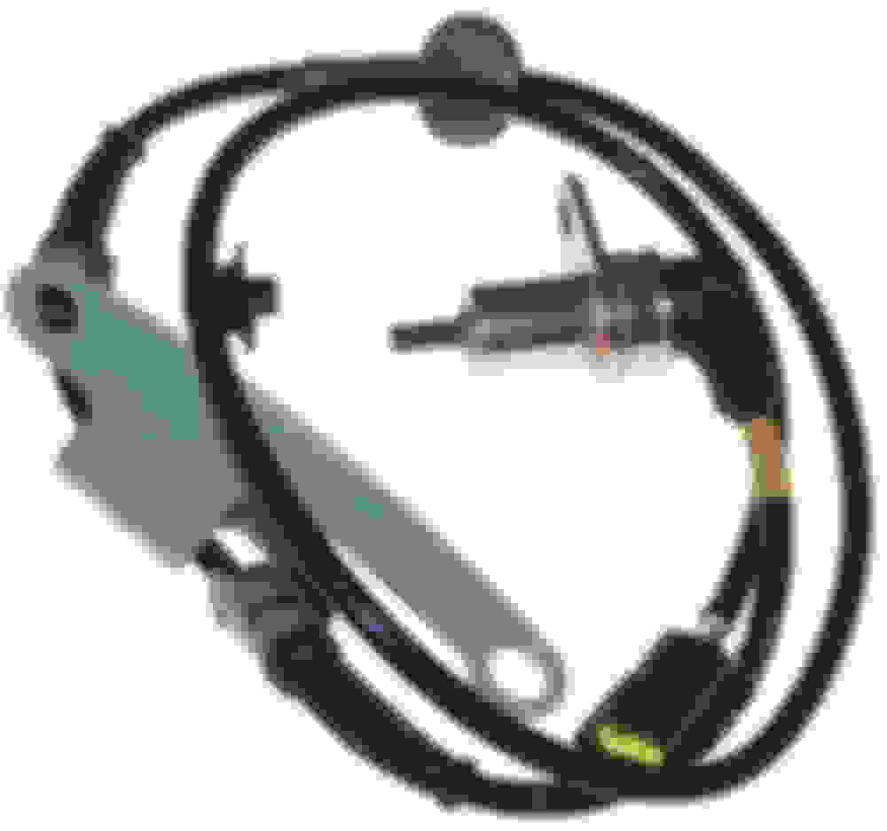
To be clear, are you suggesting to use this groove around the main housing of the sensor (see photo) with a screwdriver? That should create a prying force at key points around the sensor.
I think I just rotate and pull with my hand, maybe when the sensor is lifted a little you can help it a little with a screw driver under the bracket, but I wouldn’t do any prying on the sensor itself.
Shipmate, here is what the ABS Sensors look like... it may help.
I'd spray your favorite snakeoil from the opposite side and along the mounting flange. Then I'd LIGHTLY tap the mounting flange edge to get it to rotate and break the seize. Should simply pull straight out then.
Last edited by Carlos Iglesias; Feb 20, 2022 at 02:59 PM.
Here's what I would do. After marinating heavily in PB Blaster, I would get a sharp putty knife and have at it at the points where I drew the arrows. Looks like you'll have easy access, and it should be able to pry under the sensor flange to get it started out.
Thank you both for the recommendations. I already tried to tap on the front side of the sensor (at the magnetic pickup) with a wooded dowel and made some small dents. Does that tab sit in a recess of the steering knuckle? I may have misunderstood the direction of rotation.
@ZE Power MX6, et al, is this what you mean by tapping on one side to rotate the sensor? That should work as long as there is no recess.
Yup, IIRC you can only get it to move very little clockwise in that picture before it hit the knuckle. Leave a little room so you can slip a flat head in there and force it to go counter clockwise. You’ll have a bit more room going counter clockwise, but will still be restricted by the length of the sensor wire. Then you just have to keep moving it little by little while getting some PB Blaster in there, eventually it will loosen up enough that you can rotate it by hand. It took me awhile, and yours seems to have way more corrosion than mine unfortunately.
Thank you both for the recommendations. I already tried to tap on the front side of the sensor (at the magnetic pickup) with a wooded dowel and made some small dents. Does that tab sit in a recess of the steering knuckle? I may have misunderstood the direction of rotation.
@ZE Power MX6, et al, is this what you mean by tapping on one side to rotate the sensor? That should work as long as there is no recess.
Installing a new sensor should just slides into position (and rotate freely). The bore tolerance is (OEM) tight but not a press fit. I think your challenge is separating the large surface area corrosion between mounting tab and the mounting surface. @ZE Power MX6 and I were in technique concurrence.
Personally, I'd stay away from any impact to the actual sensor side if at all possible. Some last resorts to try and break the seize I think are:
I've found these things to be a straight pain in the past too. They also are easy to damage if you yank too hard or impact them. Best bet is to use PB blaster to soak and get a good set of gloves on and really just rock the sensor left to right in it's position. It will swivel loose eventually. I would try not to pry it because I've broken one in the past prying it out. If you have the car up in the air high enough you can stand, sit, or lie down behind the knuckle and get a good view of it to begin rocking the sensor back and forth. It is really the corrosion and dirt that gets into the sensor well that junks up the sensor coming off.
Quick update: I removed the front left (driver) ABS Wheel Speed Sensor! It was very difficult. I removed the wheel hub to gain the most access to the sensor. I'll post some pics tomorrow as I had a long day today. The sensor had all sorts of mung around it, and a river of rust flowed from all its nooks and crannies. One thing of note: the bore has raised tabs that retain the sensor. I assume these tabs keep the sensor locked in place and isolated from vibration. Maybe? These tabs also squeezed the sensor shell during removal. It went from being a round shape to a hexagonal or octagonal shape.
Another critical error on my part was the use of a dead blow hammer when trying to break the bond between sensor and wheel hub. Shortly after I switched to a standard hammer, the sensor housing began to rotate.
Ok, here are some photos that show the driver side ABS wheel speed sensor after removal. Keep in mind, I removed the wheel hub on the driver side in order to get better access to the sensor. You will also see bite marks on the sensor housing. Those came from the use of vise grip pliers. I did my best to keep the housing cushioned with a paper towel (easy to trim) then clamped the vise grips on it so I could wiggle it around.
You can clearly see the uniform impressions on the metal case.
From this angle, you can see bite marks. The gouge came from a screwdriver. It pierced the case.
You should be able to see the centering nubs/tines through the ABS Wheel Sensor bore. This causes the hexagonal shape on the case when trying to remove it.
I tired to get a better shot of the nubs/tines. Look at all that corrosion!
In some of the photos with the sensor, you could see the head of the can slightly dented inwards. This was the result of using a socket over the magnetic pickup and tapping on the head while twisting the back end of the sensor. As I previously stated, I tried to use a wooden dowel and a hammer to push out the sensor. That only dented the case so that process was quickly abandoned.
I spent 4 very frustrating hours removing the front right (passenger) side ABS Wheel Speed Sensor today. My goal was to remove it without removing the wheel hub and dust shield. Photos will show my work. I quickly got the sensor housing to rotate using a standard hammer and a 1/2-inch drive 6" extension. I frequently applied PB Blaster to keep the lubricity high. I noted the degree of rotation on the passenger side was a lot smaller than the driver side. This may be the result of restricted access (dust shied & wheel hub still on).
I got the sensor loose enough to rotate using the vise grip pliers cushioned with a paper towel. It still left bite marks but was acceptable. After swearing like a Sailor and rocking the sensor from side to side, I was able wedge a long screwdriver between the steering knuckle and the black plastic backshell. I applied a small amount of force on the screwdriver because I didn't want to break that backshell. In hind sight, it's fairly robust because I was man-handling it like it owed me money. Although, I wouldn't recommend trying to pry on it like you are trying to break torque on lug nuts.
I manipulated that sensor to a point where I could wedge a screwdriver between the top of the sensor housing and the steering knuckle. At this point, I used the screwdriver like a wood-splitting wedge. If you attempt this route then be VERY careful. You could easily pierce the can with the screwdriver. I started with a thin & narrow screwdriver then worked up to larger ones. It is equally important to monitor the magnetic pickup to ensure it doesn't get snagged on the pickup ring (I don't remember the proper term for that cog). Another important thing to consider is the lack of other angles to pry on the housing. This means the sensor was extracted at an angle. This could easily lead to excessive damage or get stuck. There were many instances where the sensor would get stuck. Luckily, tapping on that lower tear drop would free it.
I also ran an M8x1.25 thread repair tool through the screw holes for the ABS Wheel Speed Sensor on each side. The Driver Side threads were really crap-tastic. I thought the threads were beyond repair but I persisted and made sure the repair tool was centered and square. It was very dicey but slowly running the repair tool in and back out yielded good results. Now the bolts run in and out without any issues.
I also plan to hit the bores with a Dremel tool & wire wheel to remove all that corrosion. My goal is to apply nickel-based anti-seize or maybe some wheel bearing grease to the bore. This may help reduce galvanic corrosion and maybe make it easier for me (or the next guy) down the road. What do you guys think? Should this area be treated and what should be used?
And now the photos!
Front Right ABS Wheel Speed Sensor. There is a gap at the top but hard to see.
Better angle of the gap at the top. This is where I inserted a screwdriver to act as a wedge
. Screwdriver wedge. Be VERY careful not to pierce the housing! Work with narrow & thin screwdrivers up to wider & thicker ones.
Here is the same hexagonal impressions left on the sensor housing as a result of the extraction.
Different angle of front right ABS Speed Sensor housing. The hexagonal deformations are very apparent here.
Backside of steering knuckle and ABS Wheel Speed Sensor bore. Corrosion is very evident here! The centering nubs/tines are barely visible.
Holy cow... that was some yeoman's work you did in both the removal and archiving the process for prosperity! That mess has all the hallmarks of living in shore towns and/or the devil of salted road. If not for living in bone-dry Texas, I'd follow your lead and pre-emptively apply nickel anti-seize to all four corners to save some future knuckles.
Thank you both for the compliments. Sgtblue, when you decide to tackle this project, I hope this thread will help! Do plan to expend a handful hours removing these sensors. I have one more update with photos to provide.
I broke out the dremel tool and 3 shaped wire wheel brushes to clean the sensor bores today. I also gave that area a healthy coating of anti-seize. You should be able to see the 6 tines inside the bore since removing all that rust. I am debating on the replacement of the ABS Wheel Speed Sensors. One of them has a punctured housing (driver side) and the right side may have a couple of dents but does not have a compromised can. They both have some corrosion on the exterior housings so it maybe wise to just replace them, especially after being deformed during removal. Removing the rust from the right (passenger) side was a little more challenging because the wheel hub and dust shield is still on. So that limited my degrees of freedom and attacking the problem from one (rear) side. For anti-seize, I used the Permatex nickel-based stuff. I normally use it on most nuts & bolts to cut down on corrosion, galling, and as the name states - seizures.
This was all in preparation to remove the shock struts. I'll probably document those steps later. For now, I easily removed one shock strut. It was pretty straight forward but I'll save that for another thread. Here are the photos for the ABS Wheel Sensor bores:
Front Left (Driver) Side bore after cleaning with a dremel wire wheel. View is looking from the steering spindle. Rag covers spindle.
Front Left (Driver) side, from behind the steering knuckle. Cleaned up as much corrosion as possible. There were some tough spots in the corners but I got them!
Front Left (Driver) side, looking from wheel spindle (covered by rag). This is the nickel based anti-seize compound.
Front Left (Driver) side, from behind the steering knuckle. It looks like an excessive amount and that was after wiping most of it away.
Front Right (Passenger) Side, looking from wheel hub at dust shield and bore. You can clearly see the tines in this bore.
Front Right (Passenger) Side, from behind the steering knuckle. Couldn't get it as clean as the driver side because of poor angles with the dremel tool.
Front Right (Passenger) Side, looking from wheel hub at dust shield and bore. Nearly the same photo as before but with anti-seize compound applied.
Front Right (Passenger) Side, from behind the steering knuckle. Anti-seize applied to area including the screw holes.
Whoops, I have one small replacement photo to insert. This is the proper photo that shows all the corrosion removed from the Driver side sensor bore and mount point.
Replaces 2nd photo from Post #20. Front Left (Driver) side, from behind the steering knuckle. Cleaned up as much corrosion as possible. There were some tough spots in the corners but I got them!
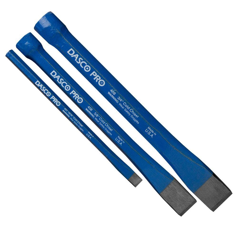
Late to the party. I commend your work. I did this last year and it's a real bitch. Once I got an assortment of these small chisels it changed the game. Made separating the bracket from the knuckle much easier.
good job on the clean up and documentation
a little smear of grease or anti-seize type stuff in the bore will hopefully help prevent that in the future