When you click on links to various merchants on this site and make a purchase, this can result in this site earning a commission. Affiliate programs and affiliations include, but are not limited to, the eBay Partner Network.
Mazda moving to a RWD platform for the Mazda3 has been one rumor floating around as well as platform sharing with the new RX.
That would work well if they do make the new RX some crazy Hydrogen-boosted gasoline engine that either adds a lot of cost with on-board Hydrogen refinery or limited market with Hydrogen tanks fueling.
Not to mention limiting its market just by being rotary powered.
--------
As far as the range extender RE, my understanding is that will be a continuation of the range extended Mazda2 they already produced and available in 2019.
The range extender rotary didn't meet international emissions standards, as you can see by the patents Mazda have been working on the evaporative emissions.
I have been poking around looking more at the Hydrogen boosted gasoline / Hydrogen enhanced combustion engines.
The steam reformer that converts gasoline to Hydrogen rich gas is a bit bigger than a football and uses conventional Platinum catalyst technology and fairly low power, so it is currently feasible for a production car.
Rotaries are easy/safe/cheap with Hydrogen injection because of the separate engine locations for the 4 strokes (a cold intake inlet side) although this technology is certainly viable for piston engine cars as well with additional costs.
There is current work being done on Hydrogen boosted gasoline rotary engines such as in these articles.
HC, CO and CO2 emissions were reduced by 79.4%, 86.0% and 25.9% when hydrogen volume fraction were raised from 0% to 6.8%.
Also boosts gas mileage 20-30% from the lean running capability.
Further, a 10% Hydrogen mixture (% by power on this stat) raised gasoline octane 5 full octane points so your 91 octane becomes 96 octane which is pretty handy for a turbo rotary such as in Mazda's patents.
If you add some on-board Hydrogen storage capability (takes lots of space, but very little weight- long hood?) you can do cold engine starts on Hydrogen and limited idle/cruising on Hydrogen with zero emissions.
New rotary-related patents released by Mazda and found on the Japanese patent office website, even though they pertain to the RE range extender.
Patent 2017-044078
How to inject oil from the upper plate without having the oil injector stick up above the engine
The oil injection hole (83) is located where injection can take place at a relatively low pressure and where the corner seal passes, so that che corner seals can help spread the oil to the upper plate.
3 piece apex seals are back
patent 2017-053332
Fuel injector strategy for liquid fuels (like gasoline). Fuel injection takes place in the very early part of the intake stroke to maximise the time available for the fuel to vaporize. Also, injecting the fuel opposite to the main airflow in the engine promotes better air-fuel mixing and further improves evaporation.
When using gaseous fuels, evaporation is no longer a concern. But the same injector location can be reused with only a revised injector, to perform late-intake injection.
The oil is injected to the side housings probably because it cools the side seal better using less oil than the rotor housing injectors on the renesis. The 3 piece apex seal is probably for emissions and fuel economy.
And is that a peripheral intake port with a side exhaust port???
I don't foresee drastic differences between a range extender and a prime mover rotary. It would cost too much to manufacture.
arghx
The oil is injected to the side housings probably because it cools the side seal better using less oil than the rotor housing injectors on the renesis. The 3 piece apex seal is probably for emissions and fuel economy.
And is that a peripheral intake port with a side exhaust port???
I don't foresee drastic differences between a range extender and a prime mover rotary. It would cost too much to manufacture.
The oil is injected onto the side housing because Mazda fixed the leaky rotor oil sealing rings on their new oil study, so the the side seals needed "some" lubrication.
Yes, the peripheral intake and side exhaust rotary is used for the RE range extender.
The range extender RE is a completely different engine than the 16X design- it is much smaller at 330cc.
The engine was already trialed in the prototype testing phase and even press tested in the last generation Mazda2 EV.
You can catch up on the design here in this 2013 video-
The oil is injected to the side housings probably because it cools the side seal better using less oil than the rotor housing injectors on the renesis. The 3 piece apex seal is probably for emissions and fuel economy.
And is that a peripheral intake port with a side exhaust port???
I don't foresee drastic differences between a range extender and a prime mover rotary. It would cost too much to manufacture.
In the patent it is said that the main issue is that, since the engine is designed to run with its shaft oriented vertically, injected oil has a tendency to fall to the bottom plate, leaving the top plate dry. Or at least this is what I got from the machine-translated japanese patent text
However, if one compares the patent drawings with the engine shown in the video, it's clear that the oil injection hole is in a completely different location. In the patent it's fairly close to the intake port, while in the video it's much closer to the combustion area.
Also, I'm not sure that the oil injectior position in the engine in the video is horizontal, as shown in the patent.
Another thing: the small hole in the rotor housing matches the position of the fuel injector shown in the patent, so the engine might rely on just side plate oil injection (plus gravity) to lubricate all side, corner and apex seals.
In any case, both the side plate oil injection scheme and the fuel injector locations may be applicable to a twin (or multi) rotor prime mover rotary engine, so I think that these patents should not be intended strictly as "range extender only" stuff.
The engines shown in the patents are not all the same engine nor necessarily patented for the same purposes.
The engines shown in the patents are not the same engine as what Mazda produced in 2013 for the last generation Mazda2 EV rotary range extender.
Some patents could be a refinement of the actual 2013 engine (like rotor stop position to cover evaporative emissions) and some patents are possible variations of 2013 engine (such as having a liquid fuel injector or a gaseous fuel injector fitted).
neit_jnf
Is the side plate oil injection in addition to rotor housing or in place of? How are the apex seals lubricated?
fmzambon
Another thing: the small hole in the rotor housing matches the position of the fuel injector shown in the patent, so the engine might rely on just side plate oil injection (plus gravity) to lubricate all side, corner and apex seals.
In the actual 2013 engine the small hole above the intake port on the rotor housing is the apex seal oil injection location.
The fuel injector is located on the intake manifold, not on the engine.
You can see this in figure 15 in this PDF file Mazda put together on the system.
According to Mazaya Kodama, Mazda CX-5 program manager, Mazda's R & D department is committed to making the Mazda RX Vision a reality. That he says in an interview with AutoRAI.nl. The spectacular concept car debuted in 2015 at the Tokyo Motor Show and has since been under development. Kodama knows what to do: start saving.
We are suppose to see the engine this year. Tokyo Auto show can't get here soon enough.
Yep.
Mazda itself in its FY 2017 presentation documents explicitly mentioned a "Vision model representing the future of Kodo design" due in autumn 2017. So we might even get something more than the engine alone.
Jesus. I hope they release it while I can still drive...
stay healthy and in 2 years we should have a new rotary. I hope.
Now that Toyota has announced their partnership with Mazda I am much more confident about a new rotary. Mazda is too small to go without a major partner.
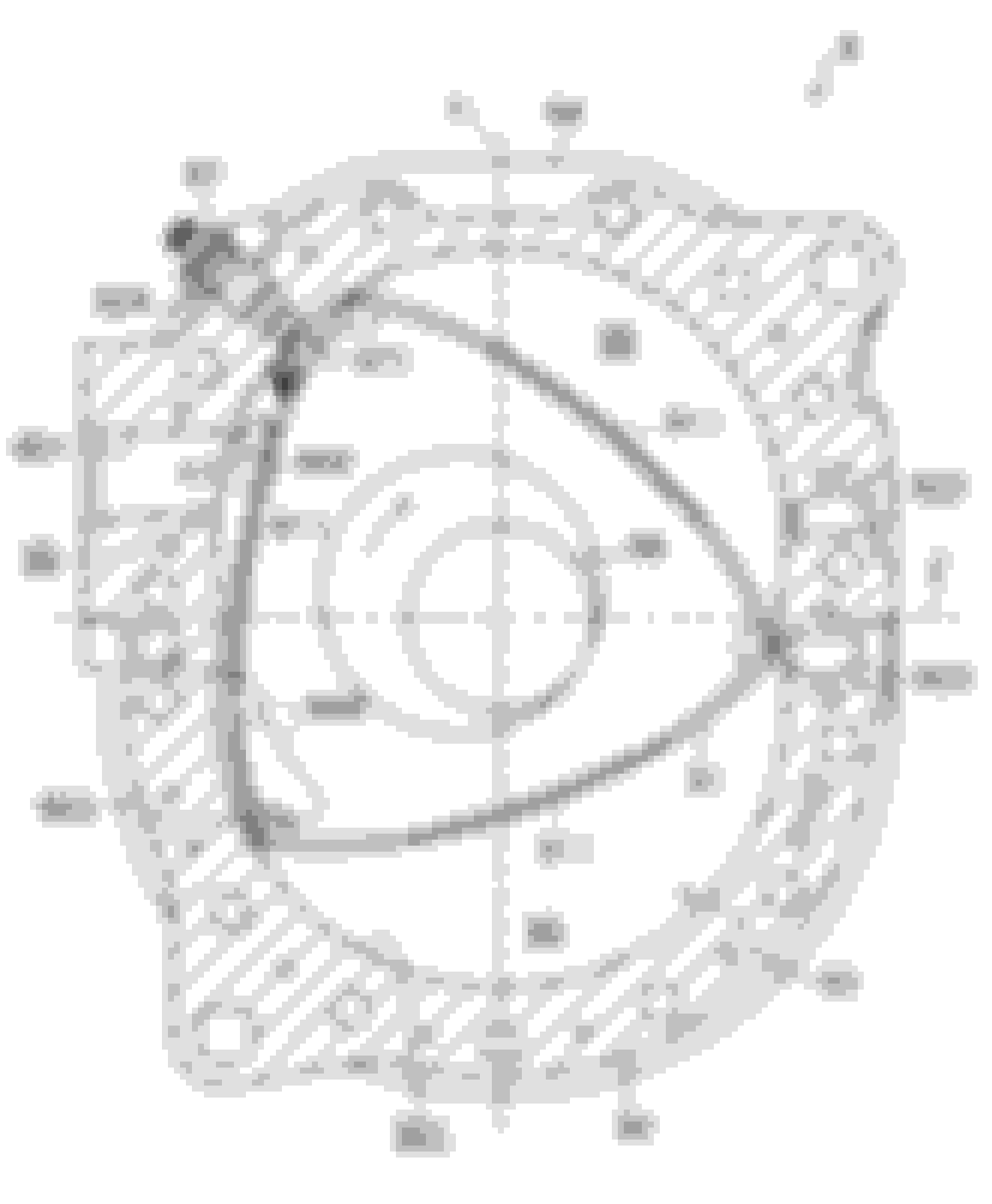
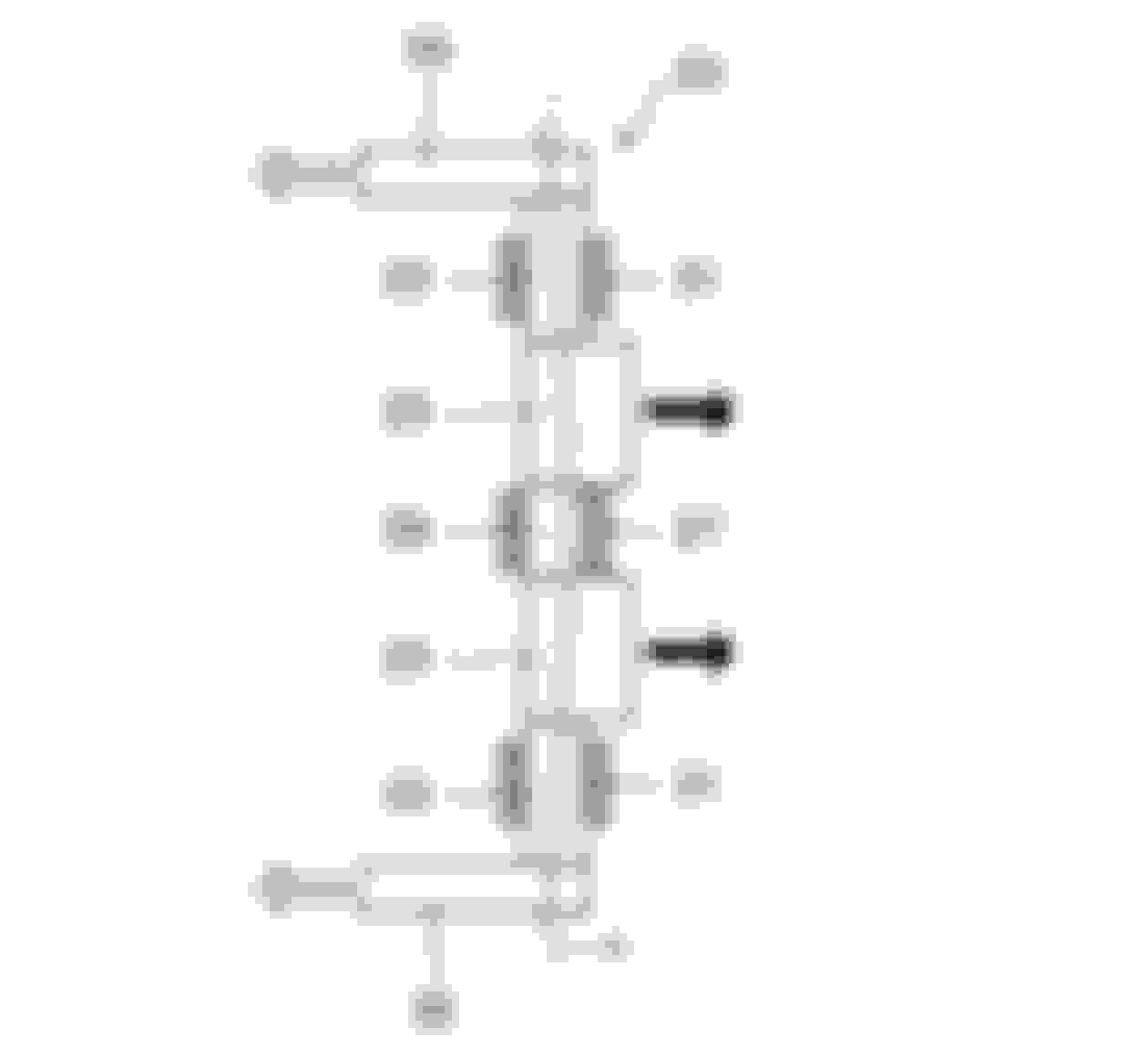
The first one is patent 2017-082708, which describes a rotary engine where every other rotor has beed "flipped over" to try and compensate for the unequal heating of the various parts of the engine.
Specifically, the patent is concerned with a turbo engine, and so the proposed engine uses two small turbos, one per rotor.
The "flipped over rotor" approach also solves the "siamese" exhaust port problem, as each rotor would have its intake and exhaust ports where the other rotor has nothing protruding in the side plates, so each rotor could have full sized ports.
Also notice how the e-shaft would need to be modified to maintain the uniform firing intervals of the current two rotor engines: instead of having 2 lobes set at 180� from each other, the proposed engine uses an e-shaft with two lobes set at 0� from each other. The patent seems to imply to me that a bearing in the center plate would be needed, but I'm not 100% sure as there was some "lost in translation" problem in that area of the patent text.
Intake and exhaust port locations. The rear rotor is normal, while the front rotor is flipped over.
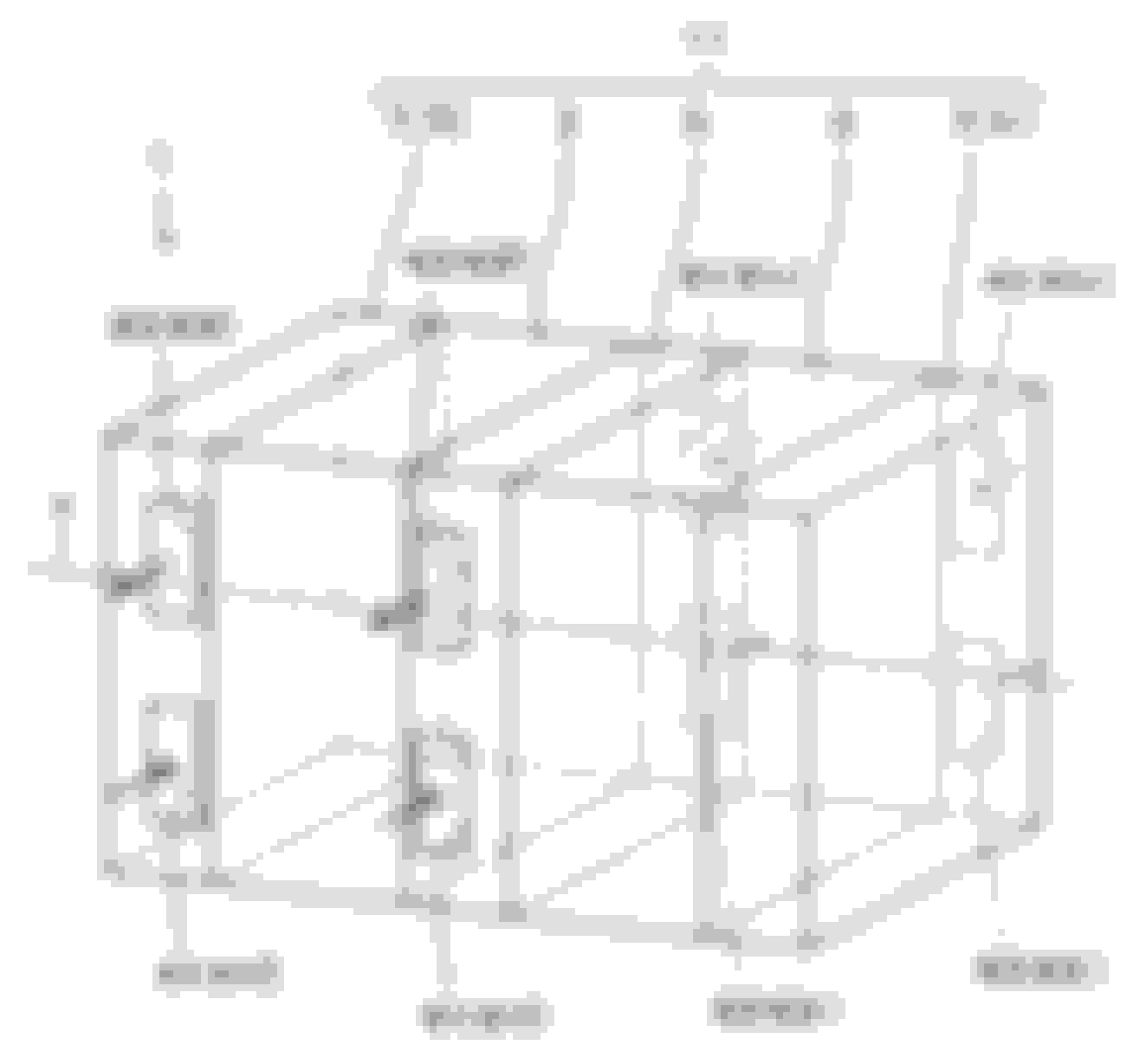
Top view of the engine. Front of the car is to the left
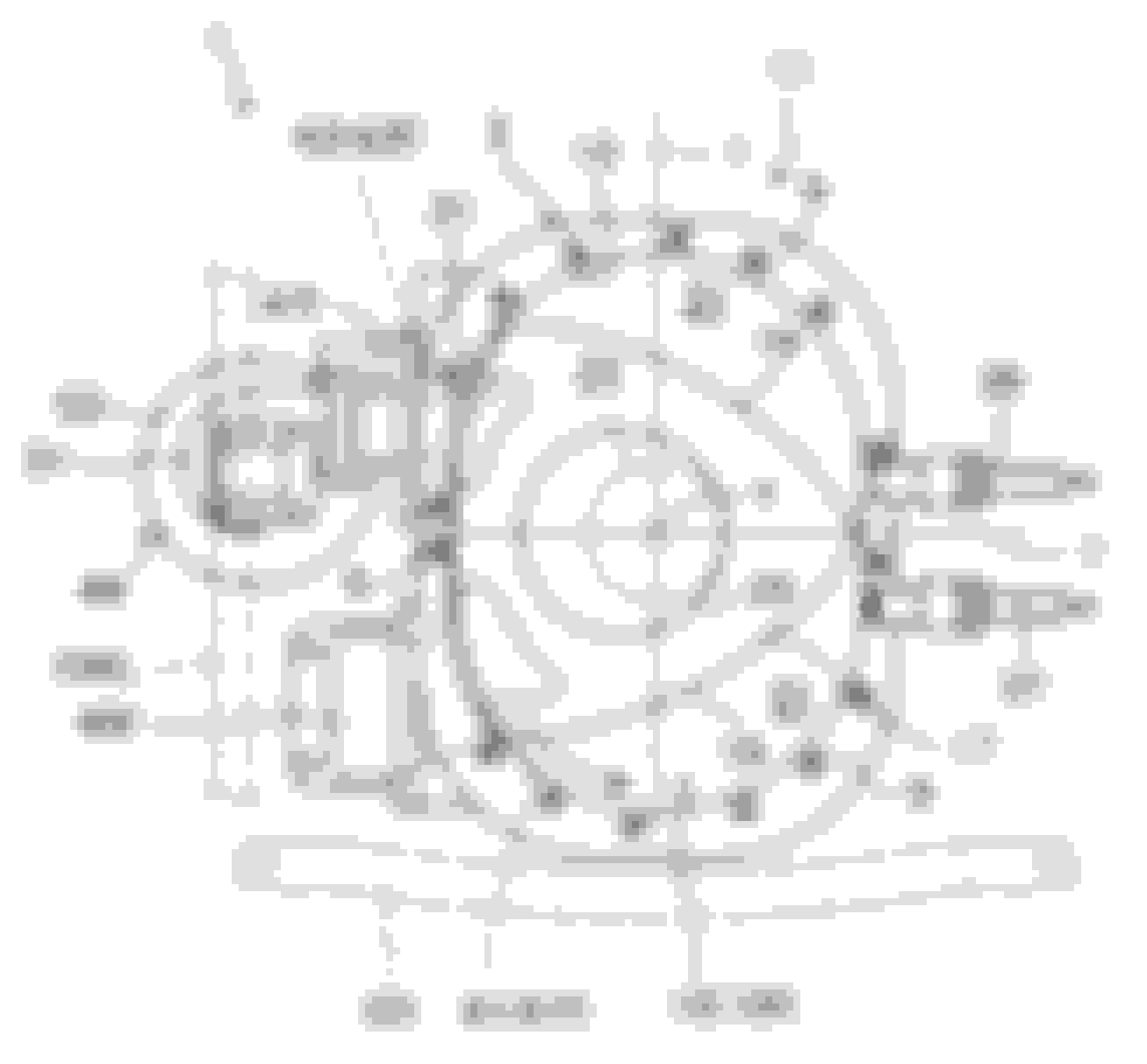
Front rotor viewed from the rear of the engine. Notice how thin the rotor housing is, Almost too thin in the spark plugs area
Rear rotor viewed from the rear of the engine. Not much room for an oil sump between the trochoid shape and the suspension member under the engine. Dry sump maybe? Or maybe a very small sump wedged between the structural members 101 and 103?
E-shaft configuration. Notice that 27 and 29 seems to indicate that a center bearing would be provided in this design.
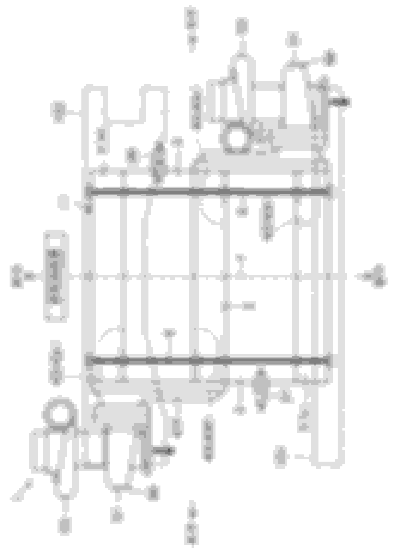
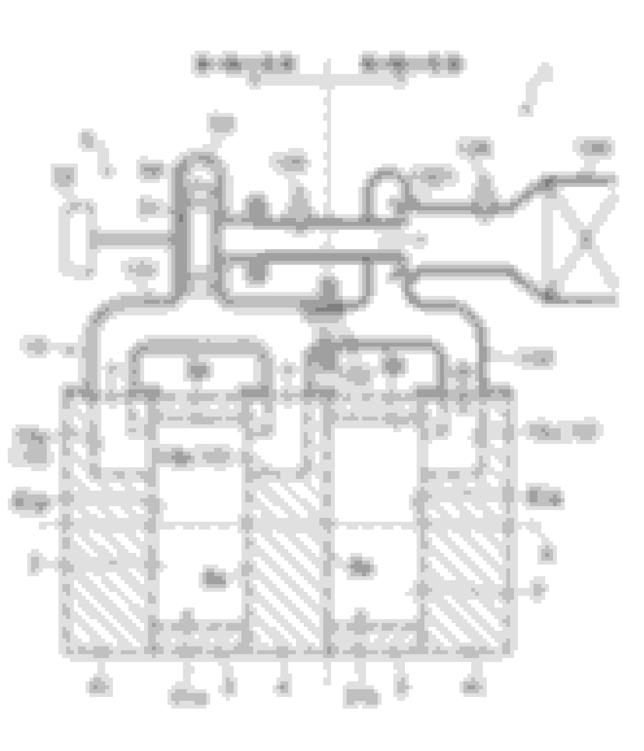
The second patent, 2017-082742, is specifically concerned with solving the "siamese" exhaust port problem.
The idea is to have two different exhaust port configurations in a given engine. Some rotors use the first configuration, while others use the second.
Rotors with the first type exhaust system have two full-sized exhaust ports that are used to drive a turbo.
Rotors of the second exhaust type, on the other hand, only have one exhaust port, but their exhaust bypasses the turbo. The idea is that by avoiding the back pressure of the turbo, the exhaust flow resistance of the two rotor types can be matched reasonably well.
Since only some of the rotors are driving the turbo, the exhaust of the other rotors can be arranged to provide an "ejector" effect in the exhaust to forcibly pull out exhaust gases from the turbine, thereby increasing the pressure differential across the turbo.
Also, the hot exhaust gases being sent straight out without being cooled by the turbo can help warm up the catalyst quicker, which is critical for cold start emissions. The valve 133 in the drawing is intended to send all of the exhaust gases straight to the catalyst 100 during cold start to improve this effect.
Also notice how the turbo is supposed to be a variable geometry turbo (see the small control vanes 54). I was under the impression that VGT do have problems with the hot exhaust of gas engines, and the rotary has one of the hottest exhausts of any automotive engine AFAIK. So mixing a rotary with VGT doesn't sound too good to me, but maybe I'm missing something.
By using multiple O2 sensors (134 and 135 in the drawing), it's also possible to know the exhaust O2 content of each rotor, which is important to know if something is wrong in just one rotor.
It's also interesting how the patent spends a paragraph describing how this layout could be applied to a 3 rotor engine, with the middle rotor being the one with two exhaust ports and thus the one that drives the turbo, while rotors 1 and 3 would have just one exhaust port each.
The rotor on the left has a "first type" exhaust system, with two full exhaust ports feeding the turbo. The rotor on the right only has a single port that bypasses the turbine.
I think one of the reasons we are seeing here patents for radical Re imagining of the Wankel engine is that Mazda scrapped the assembly line and isn't stuck with old tooling. I would have never thought of that first arrangement, because my ideas of a rotary are so confined to what Mazda made from 45 years. All he engines they put into production were pretty similar in concept.
it's like when reverse flow V8 engines came out with the exhaust inside the V.
Also notice how the turbo is supposed to be a variable geometry turbo (see the small control vanes 54). I was under the impression that VGT do have problems with the hot exhaust of gas engines, and the rotary has one of the hottest exhausts of any automotive engine AFAIK. So mixing a rotary with VGT doesn't sound too good to me, but maybe I'm missing something.
in the 1970's the Rotaries exhaust was probably hotter than any piston engine, but in 2017 its almost cold. Arghx posted the BMW twin turbo engine paper when it came out, but that thing runs temps that would melt a rotary.