
Warning Cluster Teardown - Corrosion and Other Issues (w/ pics)

Thread Starter
Joined: May 2006
Posts: 4,219
Likes: 3
From: Murfreesboro, TN
Originally Posted by jgrts20
that thing looks toast, buy another one. Unless you would like to try fixing it for the experience.
Originally Posted by My5ABaby
Originally Posted by My5ABaby
I have another one in now and it works just fine. I'd like to fix this one for several reasons.
1. It's the one that came with the car and I want to keep everything as stock as possible.
2. It's a project for me. I've never soldered anything like this before (or much in general besides playing around with some wiring to practice). I bought a de-soldering iron just yesterday to do this.
3. I'd like a spare to keep around.

Thread Starter
Joined: May 2006
Posts: 4,219
Likes: 3
From: Murfreesboro, TN
Originally Posted by Aaron Cake
The black spot is perfectly normal on a VFD.
Originally Posted by Aaron Cake
The metal can is a crystal. Just carefully resolder it and then glue it to the board.

Thread Starter
Joined: May 2006
Posts: 4,219
Likes: 3
From: Murfreesboro, TN
Alright, hopefully this will be my final question...
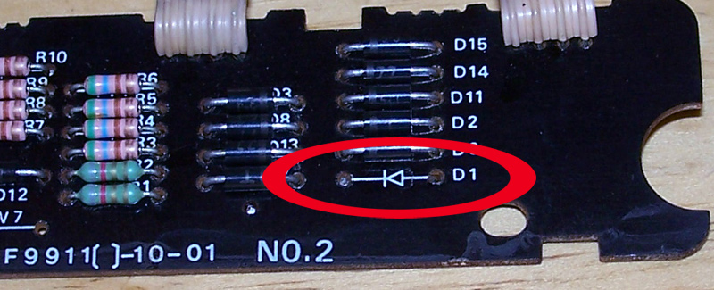
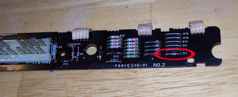
I was going over my soldering and such (visual/ohms) before putting it back together and noticed something. I think I'm missing a diode. I don't remember one there when I took it apart and my pictures from when I first did verify that. However, there is a broken piece of metal on one side. I'm guessing I knocked it off on accident or it fell off before I got to it.
Can anyone verify that I am, and if so, what diode I'll need to buy to replace it?
Thanks.
If the pics don't work, it's on the board where the plug goes and it's labeled D1.
Thread Starter
Joined: May 2006
Posts: 4,219
Likes: 3
From: Murfreesboro, TN
J-Rat rules! I got some shiny new capacitors so all I have left to do is solder one in, solder the jumper wires (3 of them  ), and figure out what diode I'll need.
P.S... anyone know what diode that is?
), and figure out what diode I'll need.P.S... anyone know what diode that is?


do you have the wiring diagram? if you do, look on it for d1 and it should tell you if you need it or not. Also the diagram will have the values for it, if you need to take a quick run to radio shack and buy a new one. if you have the wiring diagrams, let me know i will read them over and see where the circuit path goes for d1, if you need the help. anyway your worklooks good, in some cases better than people I have seen trained to do that type of work. aslo if you dont have that, then just bring the card into radio shack and get the same type as the other diodes. I cant see from the pics what their values are, plus I cant remember them off the top of my head, but it should be to hard to find.
Thread Starter
Joined: May 2006
Posts: 4,219
Likes: 3
From: Murfreesboro, TN
Originally Posted by jl1rx7
do you have the wiring diagram? if you do, look on it for d1 and it should tell you if you need it or not. Also the diagram will have the values for it, if you need to take a quick run to radio shack and buy a new one. if you have the wiring diagrams, let me know i will read them over and see where the circuit path goes for d1, if you need the help. anyway your worklooks good, in some cases better than people I have seen trained to do that type of work. aslo if you dont have that, then just bring the card into radio shack and get the same type as the other diodes. I cant see from the pics what their values are, plus I cant remember them off the top of my head, but it should be to hard to find.
I looked in the FSM wiring diagram just now (hadn't even thought of it
 ) and it doesn't say anything about the diodes that I can find. I found them on the layout but it doesn't have any specifications about them.
thats cool, take the card to radio shack and get one that looks like the others, from the pics, it looks like they are all the same, but i know i could be wrong on that. Anyways just get one that has the bands the same colour as the others and call it good.
Trunks are for corpses.
Joined: Nov 2003
Posts: 189
Likes: 0
From: St.Pete FL
When you dismantled your warning light cluster did you have any trouble getting the little black rubber spacers out in one piece?
Mine disintegrated when i took it apart.
Are they really necessary?
Mine disintegrated when i took it apart.
Are they really necessary?
Thread Starter
Joined: May 2006
Posts: 4,219
Likes: 3
From: Murfreesboro, TN
Originally Posted by AbortRetryFail
When you dismantled your warning light cluster did you have any trouble getting the little black rubber spacers out in one piece?
Mine disintegrated when i took it apart.
Are they really necessary?
Mine disintegrated when i took it apart.
Are they really necessary?
Joined: Sep 2005
Posts: 25,581
Likes: 136
From: Smiths Falls.(near Ottawa!.Mapquest IT!)
MY5..I have to Commend you on your "enthusiasm" to repair this Piece.alot of people would have given up by now OR turned around and simply said "Screw it" and bought a Used piece.I Think that you will Prevail With your Perserverence...if not I'll send you one out!..good luck Man..Good Job.Corrosion is bound to be Defeated!

Grand Poobah of Torque
Joined: Jun 2006
Posts: 186
Likes: 0
From: Clermont, Florida
I love threads like this, it's good to see someone whom cares for their car well enough to invest time into it like this.
Aaron Cake, thanks for your contributions as well, I know when I was starting out with my projects on the FD it took some time and personal discovery with a lot of what I did to cover the gray areas of what I was doing... the forum support seems to have boosted quite a bit in the last two years between members.
_Kris
its not that realy. its the fact that people just want things handed to tem really when 99% of the things have been discussed before. this is an interesting project. you might aswell replace the lightbulbs in there with leds.
Thread Starter
Joined: May 2006
Posts: 4,219
Likes: 3
From: Murfreesboro, TN
Since I love asking questions... ... anybody know how to polish the plastic covers? Both of the ones I have (fixing and the one in my car) have faded(?)/scratched spots that are annoying.
Thanks for the kind words  . You can still send me one if you want
I'm looking for some to rebuild for more practice. I was going to buy them and resell them for basically the same price, but free ones work too.
Oh, and I'm not going to let a little corrosion stop me! I will admit though, 24 gauge wiring is NOT fun to work with. Hell, I can barely see it much less handle it. I'll get it though. I might have to make the old lady hold it for me.
Thanks . They have some different numbers on them (about 3 different ones) that are hard as hell to read because they're dark grey lettering on near black background. From the looks of the FSM they seem to all connect the same and do the same job. I'll throw one in there and see if it works. If it doesn't I guess I'll just try another one.
I appreciate the support. And yes, Aaron has been a HUGE help. 
I also wanna thank J-Rat for the capacitors.
Yeah, I used to be one of those people. "Buy a new one or fix mine... eh I'll buy a new one." Not anymore...
I'll leave the lightbulbs in this one, but I'm working on buying a few more idiot clusters to work on. I'll try replacing the lights in one of them. When I decide to, you'll probably see another thread asking how I'm also not sure how LED's would look in this one. The 86-87 had the "box" lights that lit up the whole area instead of just the icon. Hopefully that makes sense... LED's might be bright though. I have had trouble in the past (aka anytime the sun is out) seeing them. Never good to hear buzzing and have to reach up and cover the panel with my hand just to see what's buzzing (stupid coolant...).
I also plan to do a write up for redoing the idiot cluster. I've seen a lot of answers on how to do it ("just resolder everything"), but that was still a bit vague.
... anybody know how to polish the plastic covers? Both of the ones I have (fixing and the one in my car) have faded(?)/scratched spots that are annoying.
Originally Posted by misterstyx69
MY5..I have to Commend you on your "enthusiasm" to repair this Piece.alot of people would have given up by now OR turned around and simply said "Screw it" and bought a Used piece.I Think that you will Prevail With your Perserverence...if not I'll send you one out!..good luck Man..Good Job.Corrosion is bound to be Defeated!
I'm looking for some to rebuild for more practice. I was going to buy them and resell them for basically the same price, but free ones work too.
Oh, and I'm not going to let a little corrosion stop me! I will admit though, 24 gauge wiring is NOT fun to work with. Hell, I can barely see it much less handle it. I'll get it though. I might have to make the old lady hold it for me.
Originally Posted by Aaron Cake
All those diodes look like standard rectifiers. So D1 is probably the same as D2. A standard 1N4007 will do the job.
. They have some different numbers on them (about 3 different ones) that are hard as hell to read because they're dark grey lettering on near black background. From the looks of the FSM they seem to all connect the same and do the same job. I'll throw one in there and see if it works. If it doesn't I guess I'll just try another one.
Originally Posted by dopefishlives
I love threads like this, it's good to see someone whom cares for their car well enough to invest time into it like this.
Aaron Cake, thanks for your contributions as well, I know when I was starting out with my projects on the FD it took some time and personal discovery with a lot of what I did to cover the gray areas of what I was doing... the forum support seems to have boosted quite a bit in the last two years between members.
_Kris
Aaron Cake, thanks for your contributions as well, I know when I was starting out with my projects on the FD it took some time and personal discovery with a lot of what I did to cover the gray areas of what I was doing... the forum support seems to have boosted quite a bit in the last two years between members.
_Kris
I also wanna thank J-Rat for the capacitors.
Originally Posted by SirCygnus
its not that realy. its the fact that people just want things handed to tem really when 99% of the things have been discussed before. this is an interesting project. you might aswell replace the lightbulbs in there with leds.
I'll leave the lightbulbs in this one, but I'm working on buying a few more idiot clusters to work on. I'll try replacing the lights in one of them. When I decide to, you'll probably see another thread asking how
I'm also not sure how LED's would look in this one. The 86-87 had the "box" lights that lit up the whole area instead of just the icon. Hopefully that makes sense... LED's might be bright though. I have had trouble in the past (aka anytime the sun is out) seeing them. Never good to hear buzzing and have to reach up and cover the panel with my hand just to see what's buzzing (stupid coolant...).I also plan to do a write up for redoing the idiot cluster. I've seen a lot of answers on how to do it ("just resolder everything"), but that was still a bit vague.
Last edited by My5ABaby; Feb 8, 2007 at 10:00 AM.
Grand Poobah of Torque
Joined: Jun 2006
Posts: 186
Likes: 0
From: Clermont, Florida
I agree SirCygnus, I was that way starting out... simple stuff like intake, radiator, downpipe, etc were a cake walk but when it came to the auto-to-manual swap I was rather inquisitive and could of probably found a bit more out on my own with the FSM initially before opening up to a public Q&A on the forum. I've been meaning to re-write the guide to swapping a manual into a formerly automatic FD, I looked back at some of my old threads and the info is spread about many topics/pages and some of it is inaccurate as well. :/ Just been a matter of time...
LED's would be sweet, might not even need resistors depending upon the voltage those bulbs are seeing. I plan to do that with my 240sx.
I wish I had a FC to play with, I like them more and more as time goes on but right now I'm trying to buckle down to school so I am wanting to stop gathering projects for awhile.
_Kris
Thread Starter
Joined: May 2006
Posts: 4,219
Likes: 3
From: Murfreesboro, TN
Originally Posted by dopefishlives
LED's would be sweet, might not even need resistors depending upon the voltage those bulbs are seeing. I plan to do that with my 240sx.
true it has to "see" 12v, but the circuit itself, will kick down the voltage that the lights see. So they might only have like 6 volts, but the leds might only need 3 volts. hense the need for resisters to "take" the extra voltage. the wiring diagrams usually have the the voltages that are going thru the circuits, but its looks like form the thumb nail, that these dont. but without looking at the real one i could be wrong. anyway you should consider this a possible side job, and see if any body else might pay for your work!
Thread Starter
Joined: May 2006
Posts: 4,219
Likes: 3
From: Murfreesboro, TN
Originally Posted by jl1rx7
the wiring diagrams usually have the the voltages that are going thru the circuits, but its looks like form the thumb nail, that these dont. but without looking at the real one i could be wrong.
Originally Posted by jl1rx7
anyway you should consider this a possible side job, and see if any body else might pay for your work!
Originally Posted by My5ABaby
I also wanna thank J-Rat for the capacitors.
Thread Starter
Joined: May 2006
Posts: 4,219
Likes: 3
From: Murfreesboro, TN
Ugh, I ******* hate Knoxville. I went looking for some 4007 diodes and couldn't find any at a decent price. I first went to the local (only) electronics store and they were out of the cheap ones. They had a pack of 10 for $8. I almost got it but I can't justify spending that when I can get 30 for $4 (what they were out of).
I went to 2 Radio Shack's and neither of them even had 4007's. They had 1, 2, 3, 4, and 5's... but no 7's.
Hopefully I'll be able to get the diodes this week when the electronics store gets in a shipment.
I have no idea what NAVSEA is, but sounds good!
Edit: "NAVSEA engineers, builds and supports America's fleet of ships and combat systems." Yay for Google (I think).
I went to 2 Radio Shack's and neither of them even had 4007's. They had 1, 2, 3, 4, and 5's... but no 7's.
Hopefully I'll be able to get the diodes this week when the electronics store gets in a shipment.
Originally Posted by J-Rat
Pfft.. I got tons of them laying around the shop. Keep in mind that I am also a NAVSEA certified PCB repair technician, so if you need some down and dirty repair work done, let me know!
Edit: "NAVSEA engineers, builds and supports America's fleet of ships and combat systems." Yay for Google (I think).
Senior Member
Joined: Sep 2006
Posts: 320
Likes: 0
From: Toronto/Waterloo/Niagara Falls, Ontario
Looking good on the cleanup.
Incase you were still wondering, VFD stands for Vacuum Flourescent Display. Basically, what was used before LEDs.
http://en.wikipedia.org/wiki/Vacuum_fluorescent_display
Aaron also has a good section on his site about soldering, desoldering, building tips, etc. I'm surprised he didn't link to it, but it looks like you don't really need it.
http://www.aaroncake.net/electronics/index.html
That copper mesh someone mentioned a while ago was probably a desoldering wick (Aaron mentions both types of desoldering tools and when to use them).
I don't know why people kept telling you to junk it (they probably didn't read what you already said). What better hobby is there than rx7s' than rebuilding parts for rx7's?

