
Vac Rack removal(Pic)

Thread Starter
Joined: Jun 2002
Posts: 4,403
Likes: 4
From: Avondale, Arizona
Vac Rack removal(Pic)
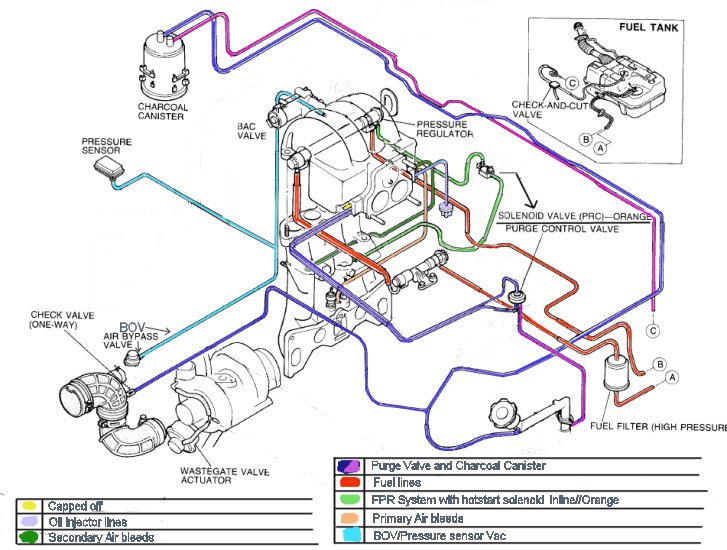
Here is a pic I modified to show the Vac rack removal while keeping the PCV/Charcoal system and the FPR hot start system.
The solenoid was jusrt placed over there to give a better idea. You will have to get a line over to the orig spot or extend that wire on the harness.
Please tell me if anything looks wrong.
Thx
The solenoid was jusrt placed over there to give a better idea. You will have to get a line over to the orig spot or extend that wire on the harness.
Please tell me if anything looks wrong.
Thx
Thread Starter
Joined: Jun 2002
Posts: 4,403
Likes: 4
From: Avondale, Arizona
too late pretty much(Already hacked rack up). Also makes me understand WTF is under there since I had no idea previously with the rack in there.
Now is the Wastegate part correct?
Should I just Cap that extra part and It no longer needs to connect to the intake because I don't have the boost control solenoid?
Now is the Wastegate part correct?
Should I just Cap that extra part and It no longer needs to connect to the intake because I don't have the boost control solenoid?

Thread Starter
Joined: Jun 2002
Posts: 4,403
Likes: 4
From: Avondale, Arizona
Well an NA is a little different because it can pull Vacuum from anywhere when a Turbo model has to pull Vacuum from before the turbo.
Also
Does anyone know if the direction of which way the solenoid is placed inline matters?
Is it a directional flow? If so which side should be the output for the FPR?
Thx.
Also
Does anyone know if the direction of which way the solenoid is placed inline matters?
Is it a directional flow? If so which side should be the output for the FPR?
Thx.
Thread Starter
Joined: Jun 2002
Posts: 4,403
Likes: 4
From: Avondale, Arizona
Also Where can I tap a boost gauage? Does it have to be before or after the throttle plates.
I can remember right now but I believe thr front Vac nipples pull Vac from behind the plates and the rear nipples pull from before them.
I can remember right now but I believe thr front Vac nipples pull Vac from behind the plates and the rear nipples pull from before them.
Trending Topics
Thread Starter
Joined: Jun 2002
Posts: 4,403
Likes: 4
From: Avondale, Arizona
Well If I can tee off of the BOV line then it would be a pressure source after the throttle plates right?
Then I could probably use that Yellow capped spot right?
BTW NZ. I have a S4/S5 TII conversion so the twin scroll and S5 Boost solenoid are useless. I'll probably get a boost controller later after the car is up and running and the AFR's are set.
Then I could probably use that Yellow capped spot right?
BTW NZ. I have a S4/S5 TII conversion so the twin scroll and S5 Boost solenoid are useless. I'll probably get a boost controller later after the car is up and running and the AFR's are set.
Last edited by Digi7ech; Apr 5, 2004 at 02:33 PM.
for the boost guage line it would be better to mount after the throttle body, that way you can measure vac and boost if you are using an aftermarket boost guage. i tapped mine into my boost pressure sensor line, teeing into the bov line would work as well.
Thread Starter
Joined: Jun 2002
Posts: 4,403
Likes: 4
From: Avondale, Arizona
I removed the ACV so I only have the single nipple on the UIM.
I also have a positive pressure only guage. I thought you may read boost spikes if you place it before the throttle plates.
Can anyone confirm if the top nipple on the front of the UIM is ok to use? Are any of them restricted where it might not read correctly/or quick enough?
I also have a positive pressure only guage. I thought you may read boost spikes if you place it before the throttle plates.
Can anyone confirm if the top nipple on the front of the UIM is ok to use? Are any of them restricted where it might not read correctly/or quick enough?
I'm a boost creep...
Joined: Jan 2002
Posts: 15,608
Likes: 8
From: Auckland, New Zealand
Originally posted by Digi7ech
Does anyone know if the direction of which way the solenoid is placed inline matters?
Does anyone know if the direction of which way the solenoid is placed inline matters?
Also Where can I tap a boost gauage? Does it have to be before or after the throttle plates.
I can remember right now but I believe thr front Vac nipples pull Vac from behind the plates and the rear nipples pull from before them.
Then I could probably use that Yellow capped spot right?
I also have a positive pressure only guage.
I thought you may read boost spikes if you place it before the throttle plates.
Thread Starter
Joined: Jun 2002
Posts: 4,403
Likes: 4
From: Avondale, Arizona
I used the picture from the FSM. Just get the NA version of the EFI manual.
THX NZ.
BTW this is a Jspec manifold and I only have 3 nipples on each side.
"Being able to read vacuum is very useful. You should get a full-range gauge."
I'd love to get a Full range but this conversion has cost me over 5k so far and I have Taxes and other things to pay for right now. I still have to get a TII hood too(CF FC3S.org).
Thread Starter
Joined: Jun 2002
Posts: 4,403
Likes: 4
From: Avondale, Arizona
I can remember right now but I believe thr front Vac nipples pull Vac from behind the plates and the rear nipples pull from before them.
--------------------------------------------------------------------------------
No, they're all different. On the rear (four nipples) the top three are fed from before the throttle and the bottom one is fed from before the throttle. On the front (three nipples) the top and bottom ones are fed from after the throttle and the middle one is fed from before the throttle.
OK,
So the stock PCV system uses a source before and after the throttle plates?
I'm just going to use the Top capped nipple for my Boost line for ease and to keep the BOV/Boost line a little more dedicated.
I'm a boost creep...
Joined: Jan 2002
Posts: 15,608
Likes: 8
From: Auckland, New Zealand
Originally posted by Digi7ech
BTW this is a Jspec manifold and I only have 3 nipples on each side.
BTW this is a Jspec manifold and I only have 3 nipples on each side.
So the stock PCV system uses a source before and after the throttle plates?


Thread
Thread Starter
Forum
Replies
Last Post
streetlegal?
New Member RX-7 Technical
13
Mar 17, 2022 02:46 PM
whizzybang
Naturally Aspirated Performance Forum
21
Feb 10, 2017 12:08 PM
turbo-minivan
General Rotary Tech Support
69
Feb 4, 2016 12:29 AM