
Spec's 400whp build up - F*** yea

Spec's 400whp build up - F*** yea
Hi all,
So I am back with a new set-up in mind. Well, not in mind, in progress rather. After 2 years of doubts and ideas, I finally have a fixed idea of what I am going to do. 2 rotor streetport with BNR stage 3 turbine with supporting mods. But also, I plan on making the set-up bullet proof...or as reliable as possible with the best fuel efficiency possible.
For a brief history for those who are not familiar withme or my last project, here is quick briefing. http://videos.streetfire.net/video/C...ors_206503.htm . (I know it should have said 2300lbs, not 2000lbs...) Now add 5 lugs conversion, TII hood, FD alt, Brembo brakes and thats pretty much where I am at now.
So, now that you are up too date, I plan on making these upgrades for my new set-up.
-13B-T streetport
I am going to rebuild my own engine. I will be using street ported S4 plates (I could use S5s but I have 3 brand new S4 ones), S5 rotating assembly, used but nearly perfect FD housings (for exhaust ports) and 3mm apex seals since housings aren't new.
-Stage 3 BNR Turbo
I have a TII BNR stage 2 turbine that I will send back to BNR to have it upgraded to stage 3 (T60-1 compressor wheel with 360 thrust bearings) Wastegate has already been ported to 28mm, which should be more that sufficient.
-Water injection
I am going to use a water injection system, probably the one from FJO but that remains to be decided.
-FC UIM TB and Elbow to FD conversion (Self adusting FD TPS, Woot!)
Since the FD TB had bigger ports (1x45mm + 2x50mm instead of 3x45mm) and longer runners, airflow and fuel atomization is greatly improved so I will be using it for these reasons, looks are just a bonus. Also, I will no be usinga spacer/adapter, I will use an S5 LIM that will be port matched to the FD UIM. I will also cut everything off the LIM so I end up with a nice cast with only 4 runners. Everything will be polished afterwards.
-2x460cc primaries and 4x720cc secondaries and custom fuel rail/LIM
I hate 1200cc and such. At low throttle, they dont spray they drip. That reduces fuel atomization greatly, hence reducing fuel efficiency, throttle response at low throttle/rpms and low end torque. Solution to this, 4x720cc for secondaries and 2x460cc primaries. I'd rather have 4x720cc at 40% duty than 2x1200cc at 25% duty. Also, using 460cc as primaries will improve coasting efficiency and make the low throttle tuning easier.
-Denso 280LHP
-Aeromotive fuel pressure regulator
I will be using a paralel fuel rail set-up so fuel pressure between lines will not differ.
-Double EGTs
Mandatory for monitoring purposes, water injection and custom safe mode that I will make.
-Double oil coolers
-AIT gauge
-Oil Temp/pressure gauge
-2 x Greedy Type-RS BOV (Hot side and cold side)
-3" intercooler piping
-Custom V-Mount set-up
-Apexi AVCR boost controller
-FJO wideband
-Power FC
I will use an FD harness (Or clips should I say) and make my own custom wiring harness that will come out of the firewall just over the bell housing behind the UIM. That way, no wires will be at wide open view. I plan on making it as seamless as possible.
-Custom gauge cluster
Replace all OEM gauges with aftermarket ones except for the speedgauge. I will use the S5 one and have a custom backing...You will see later why.
I plan on putting the engine in the car this winter and the car to be ready around June 1st 2010. So that most likely means July or august as we all know...of course.
And if you guys have any pointers, please, go right ahead, it more than welcome. But comments like "You'll fail, it cant be done" and such are a waste of my time and bandwidth also. It's my car, my money and most importantly (and in all modesty) I never fail.
So, with all this said, let the progress begin!
Spec.
So Firstly, I have the S5 cluster that I will be using. I will be making a new backing for the aftermarket gauges that will include.
-RPM
-Fuel level
-Voltage
-Water Temp
-Oil pressure
-Oil Temp
-Boost
-Wideband
-EGT x 2
And here is the speed gauge that I am keeping.

And for one simple reason. I am having a new custom backing made, exactly the same scale,, but it will reach 300km/h just like my car will. Oddly, thats where it locks exactly.

This is my fuel filter adapter for my fuel pressure and temp sensors.

My S4 waterpump filler neck all polished. Everything will be just like that except for the FD housings that will be red like my car (most likely but that could change. Ideas are welcome.)

Spec.
-RPM
-Fuel level
-Voltage
-Water Temp
-Oil pressure
-Oil Temp
-Boost
-Wideband
-EGT x 2
And here is the speed gauge that I am keeping.
And for one simple reason. I am having a new custom backing made, exactly the same scale,, but it will reach 300km/h just like my car will. Oddly, thats where it locks exactly.
This is my fuel filter adapter for my fuel pressure and temp sensors.
My S4 waterpump filler neck all polished. Everything will be just like that except for the FD housings that will be red like my car (most likely but that could change. Ideas are welcome.)
Spec.
My fuel line set-up for my paralel fuel rail system.

All I need to get is the Aeromotive FPR and 2 more SS hases.
Here are my Silicone Vacuum lines and mt FJO injector driver to enable 4x720cc secondaries.

And here is mny second Greddy Type-RS BOV. The other one is already on my car,

And the BNR stage-2 that will be upgraded to Stage-3.

Spec.
All I need to get is the Aeromotive FPR and 2 more SS hases.
Here are my Silicone Vacuum lines and mt FJO injector driver to enable 4x720cc secondaries.
And here is mny second Greddy Type-RS BOV. The other one is already on my car,
And the BNR stage-2 that will be upgraded to Stage-3.
Spec.
So, here is what the Greddy elbow looks like now.

Its been cut and welded for the exact positioning I need for My V-Mount set-up. The Greddy had disapeared in the welding but it was carved back after. Pretty good job I would say.
Here is the FD UIM and TB I will be using.

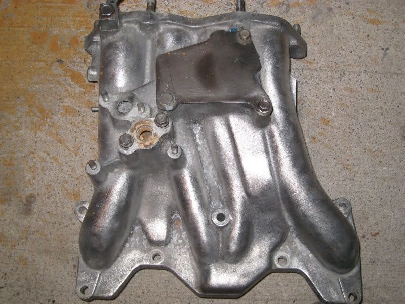
And the S5 LIM when its stock.
See next post to see what it looks like now.
Spec.
Its been cut and welded for the exact positioning I need for My V-Mount set-up. The Greddy had disapeared in the welding but it was carved back after. Pretty good job I would say.
Here is the FD UIM and TB I will be using.
And the S5 LIM when its stock.
See next post to see what it looks like now.
Spec.
And here is the S5 LIM port matched with the FD UIM. Thats the FD gasket on the S5 LIM. You can also see the 2 bongs added for 4x720cc.

And how it looks now with nothing on it and only 4 runners.

I know, its damn sexy.

All that needs to be done now are the holes on the flange and sanding/polishing. After that it'll be like new.
Spec.
And how it looks now with nothing on it and only 4 runners.
I know, its damn sexy.
All that needs to be done now are the holes on the flange and sanding/polishing. After that it'll be like new.
Spec.
Here it is matched with the the FD UIM


I will be using the TB water feed nipple to cool my turbo since I removed the original feedline from the LIM. And after the LIM is finished, I am cleaning up the FD UIM just like the S5 one. And then, the fuel rail.
Spec.
I will be using the TB water feed nipple to cool my turbo since I removed the original feedline from the LIM. And after the LIM is finished, I am cleaning up the FD UIM just like the S5 one. And then, the fuel rail.
Spec.
What is involved in smoothing that LIM? Do you just have to grind off all the excess material or do you have to weld up some holes?
The LIM looks pretty nice, i like the extra injector holders.
The LIM looks pretty nice, i like the extra injector holders.
Trending Topics

to the op that looks great i did somthing similar but didnt have the patience to go that far. nice job


-Stage 3 BNR Turbo
I have a TII BNR stage 2 turbine that I will send back to BNR to have it upgraded to stage 3 (T60-1 compressor wheel with 360 thrust bearings) Wastegate has already been ported to 28mm, which should be more that sufficient.
I have a TII BNR stage 2 turbine that I will send back to BNR to have it upgraded to stage 3 (T60-1 compressor wheel with 360 thrust bearings) Wastegate has already been ported to 28mm, which should be more that sufficient.
-FC UIM TB and Elbow to FD conversion (Self adusting FD TPS, Woot!)
Nice upgrade. The FD TPS doesn't make a whole lot of difference with the Power FC if you know how to set up the s4 TPS, but I suppose that whole point is academic at this point. The "self adjusting" TPS is a bit of a misnomer. They still have to be adjusted, it's just that the FD stock ECU was more tolerant of the TPS operating within a larger range of voltages than the FC ECU's were.
2x460cc primaries and 4x720cc secondaries and custom fuel rail/LIM
I hate 1200cc and such. At low throttle, they dont spray they drip. That reduces fuel atomization greatly, hence reducing fuel efficiency, throttle response at low throttle/rpms and low end torque. Solution to this, 4x720cc for secondaries and 2x460cc primaries. I'd rather have 4x720cc at 40% duty than 2x1200cc at 25% duty. Also, using 460cc as primaries will improve coasting efficiency and make the low throttle tuning easier.
I hate 1200cc and such. At low throttle, they dont spray they drip. That reduces fuel atomization greatly, hence reducing fuel efficiency, throttle response at low throttle/rpms and low end torque. Solution to this, 4x720cc for secondaries and 2x460cc primaries. I'd rather have 4x720cc at 40% duty than 2x1200cc at 25% duty. Also, using 460cc as primaries will improve coasting efficiency and make the low throttle tuning easier.
I will be using a paralel fuel rail set-up so fuel pressure between lines will not differ.
Double EGTs
Mandatory for monitoring purposes, water injection and custom safe mode that I will make.
Mandatory for monitoring purposes, water injection and custom safe mode that I will make.
Double oil coolers
AIT gauge
-2 x Greedy Type-RS BOV (Hot side and cold side)
3" intercooler piping
Custom V-Mount set-up
FJO wideband
I will use an FD harness (Or clips should I say) and make my own custom wiring harness that will come out of the firewall just over the bell housing behind the UIM. That way, no wires will be at wide open view. I plan on making it as seamless as possible.
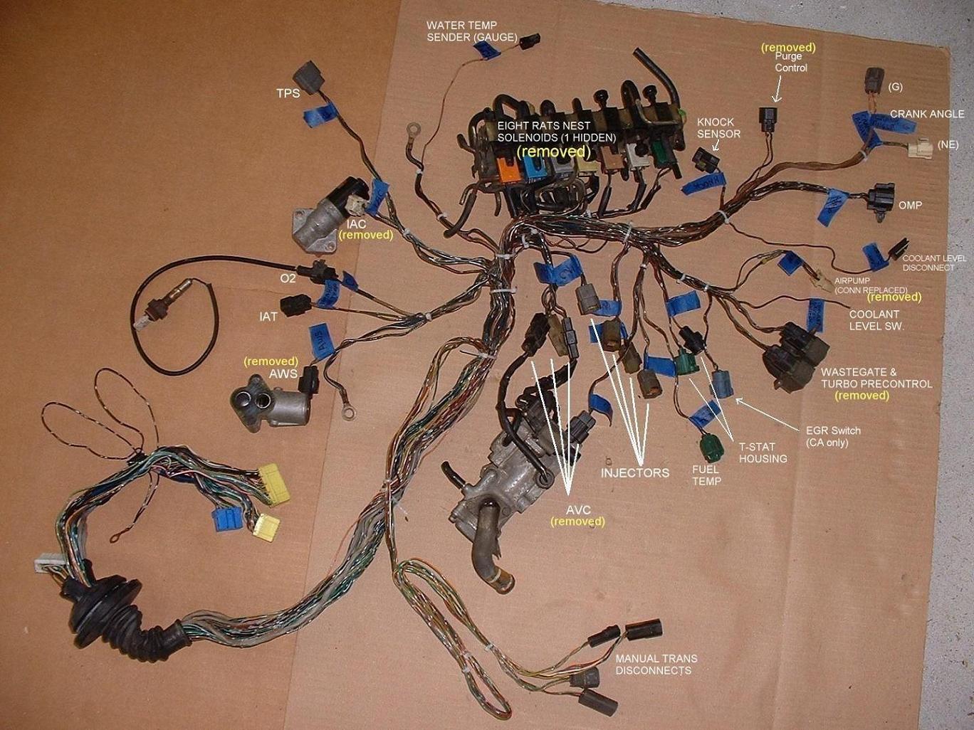
You can see that certain wires are in different locations. The crank angle sensor (Ne and G plugs) are on the main FD "emissions" harness as well as the coil wiring. On the FC, both those items are on the separate "engine" harness along with the alternator. The connectors are different on the FD harness so you will have to buy stuff like an FD water thermo sensor. Have you mapped this whole wiring harness thing out yet? I don't think you've thought this through. You've got a potential nightmare on your hands when you don't have to. "Wire tucks" can lead to biiiiig problems.
Custom gauge cluster
I understand that I haven't detailled most of the stuff I mentionned so I can understand why you would have these "concerns". Might as well clear them up now I guess.
Like I said, I have 3 new S4 plates and I dont on reaching 450whp + with that block so S4 plates will hold just fine.
As for the wastegate size, I agree, it remains to be seen. As for the 400whp mark, its a figure that I will sacrafice over reliability any day. However, I'm pretty sure I will hit it or get real close to it considering the street port, FD intake and water injection. It will all depend on the efficiency of the system and proper tune though.
Yea, it comes with the TPS, I take it as a bonus. And I call it auto adjustable because the only time you adjust it is when you bolt it on. But one question, how can you properly set a narrow range TPS on the power FC?
I have absolutely no worries about my secondary injector usage. But you bring up a good point with the 460cc...It hadn't crossed my mind yet that the PFC is at default on 550cc. For the difference it makes on fuel efficiency, it wont be worth it.
Might as well do it right the first time. I dont know what my power goals will be in 2 years time...
I forgot to specify:" Double FD oil coolers" just like on the JDM ones. The purpose is exactly to clear the way for the V-Mount intercooler.
I know, but just like the second BOV, its for looks. I had one spot left for a gauge and it didn't seem fit for a cup holder...You know, the hole being sideways-up and all.
Yup, all for looks and sound.
I know all that, I will probably lose 200-400rpms brfore I get at fullboost but it'll sound much nicer when the turbo spools up and creates friction in the piping. Its not a track car but a daily driver.
Like I said, FD oil coolers.
I am planning on using the harness to ECU connector of the FD and using the S4 harness, hence creating the adapter "kind of" in the process. I will also be using the FD MAP sensor connector, AIT connector and TPS connector. I will then cut or lengthen the wires as needed to make it fit as I wish. Its not as big of a deal. Reading connector pin-outs wont be that hard.
[/QUOTE]
No worries, I wanna see the "exhaust system overheat" light light up just once in my life. lol.
Spec.
Many would argue that upgrading to s5 plates is far more important than running 3mm apex seals. I have personally measured a 19% thicker casting in the dowel pin area on the particular set of s5 plates I acquired for my own Power FC based 400whp build. I would also like to suggest new side seals as well if they don't have a clearance of 2 - 3 thousandths of an inch.
You better find yourself a generous dyno if you want to see 400 with that turbo. I have no problems with hybrid turbos, and I even helped Bryan get his hybrid Greddy Rx-8 turbos going on the Rx-8 forums. But it's hard enough to hit 400whp with a full 60-1 T04S turbo (same wheel but not a hybrid) as I have found out on my own prior setup. As for the wastegate size... I guess wait and see. I would stiffen the wastegate actuator significantly to raise the effective spring pressure, then run low duty values on the AVC-R. I doubt you'll be able to just run at a 6 or 7psi spring with no creep. Personally I was never able to control boost until I had a 44mm external wastegate with 13psi spring. I control boost through the Power FC itself using a factory FD boost control solenoid.
-FC UIM TB and Elbow to FD conversion (Self adusting FD TPS, Woot!)
Nice upgrade. The FD TPS doesn't make a whole lot of difference with the Power FC if you know how to set up the s4 TPS, but I suppose that whole point is academic at this point. The "self adjusting" TPS is a bit of a misnomer. They still have to be adjusted, it's just that the FD stock ECU was more tolerant of the TPS operating within a larger range of voltages than the FC ECU's were.
Nice upgrade. The FD TPS doesn't make a whole lot of difference with the Power FC if you know how to set up the s4 TPS, but I suppose that whole point is academic at this point. The "self adjusting" TPS is a bit of a misnomer. They still have to be adjusted, it's just that the FD stock ECU was more tolerant of the TPS operating within a larger range of voltages than the FC ECU's were.
You're adding additional complexity to the tuning but I'm not sure you will notice a big benefit. You will have configure your secondary injectors in the PFC as two 1440's, although you may be able to use the lower injector lag/deadtime values of 720 cc injectors. You'll also have to be careful what kind of resistors you use. I have posted about calculating injector resistor size before. The 460's are smaller than the FD stock injectors. That means that even after setting up your injector settings in the ECU you may have a bunch of lean lean spots in low load driving. Your injector transition settings will have to be completely custom. I recommend the stock top feed 550's. The theoretical advantage of smaller primaries cannot be empirically shown, especially not in the context of an ECU that is configured for bigger injectors by default.
While a nice looking setup, it's completely unnecessary for your relatively modest power goals. I have a bigger turbo than you (T04R) and I am not running parallel fuel lines. But I see you have already bought the stuff so I guess that doesn't matter.
unnecessary for all but a genuine race car. the factory oil cooler is enormous and eclipses the pitiful FD and Rx-8 oil coolers.
Again, unnecessary. The Power FC commander monitors this (including a peak-hold function) and you should have that mounted within view. Consider the Triumph AIT sensor mod for a faster responding sensor, there is a thread about in the 3rd gen section
Again unnecessary, but if you want it for underhood looks that's another thing.
Again unnecessary for the turbo you have picked (which really isn't that big as I said) and it will just mean more expensive pipes, more cutting, and possibly tougher fitment. The inner diameter of your intercooler piping will be far bigger than the inner diameter of your compressor outlet. The more volume of piping you have to fill, the more likely it will hurt response. Even my T04R has a 2 1/8" ID compressor outlet which I have running to thin wall 2 1/4" OD Greddy piping with the same ID.
That's going to be tough with dual factory oil coolers... because there's no point in dual aftermarket ones when the factory ones are so good.
With an adapter kit readily available, you're really doing this the hard way. There must always be a balance between cleanliness and serviceability. What you are proposing is going to be difficult to service. There's also an increased chance of electrical problems due to the sheer number of connections that have to be made and the potential for human error or physical failure of the components. I hope you have good quality OEM-grade shielded wire for the crank angle sensor. The FD wiring harness is far different from the S4 T2:
Just don't ditch the idiot lights. They've saved me more than once.
No worries, I wanna see the "exhaust system overheat" light light up just once in my life. lol.
Spec.

Damn, cant edit...
Ok so, it has to be "Use a flat head screw driver and unclip the clips that hold them together."...or did I mean "Used a flat head screw driver and uncliped the clips that held them together."...?

Both ways should work as well though.
Spec.
But one question, how can you properly set a narrow range TPS on the power FC?
Also, replace the FD TPS philips screws with allen or hex bolts. they always strip out.
I know all that, I will probably lose 200-400rpms brfore I get at fullboost but it'll sound much nicer when the turbo spools up and creates friction in the piping. Its not a track car but a daily driver.
I am planning on using the harness to ECU connector of the FD and using the S4 harness, hence creating the adapter "kind of" in the process. I will also be using the FD MAP sensor connector, AIT connector and TPS connector. I will then cut or lengthen the wires as needed to make it fit as I wish. Its not as big of a deal. Reading connector pin-outs wont be that hard.

Thread
Thread Starter
Forum
Replies
Last Post
rx7jocke
Suspension/Wheels/Tires/Brakes
72
Jun 17, 2016 03:48 AM
SakeBomb Garage
SakeBomb Garage
0
Sep 4, 2015 05:20 PM
rx8volks
Canadian Forum
0
Sep 1, 2015 11:02 PM