
SAFC Neo & Zeitronix WB on S5Tii

SAFC Neo & Zeitronix WB on S5Tii
I've got the 1300cc writeup on how to install the SAFC wiring. It appears that it uses the ECUs power and ground to drive the SAFC.
One thing I noticed different is that the Apexi instructions say to hook up the red/white wire as well which the 1300cc instructions dont. The 1300cc instructions also say the brown and black ground wires need to be 1cm apart. That seems silly and I cant find any text in the manual that confirms that. I'm guessing the author interpreted that from the wiring diagram.
At the same time I'm wiring up the Zeitronix WB. Their instructions are pretty light.
They both have switched power, rpm inputs, TPS input, power gnd and sensor ground.
My plan is to hook the corresponding SAFC and Zeitronix wires together. I'm assuming that the power draw on the SAFC and the Zeitronix combined won't affect the ECU.
Or should I hook the two power grounds together and run them to the chassis?
Will I be Ok?
Thanks,
Jim
Factory or DPO?
Per the Apexi instructions I prepped the harness wires and saw a couple of things that surprised me.

This shows the ground wire specified by the Apexi instructions. Notice that it has at some point been spliced. Would that be factory? The car has shown no signs of ever having been hacked at anywhere, even the factory radio was in it when we got it.

This image shows a big *** grounding block. This surprised me too because I've been through Aaron's grounding procedures and dont recall anything like this being mentioned.

Thanks!
Jim
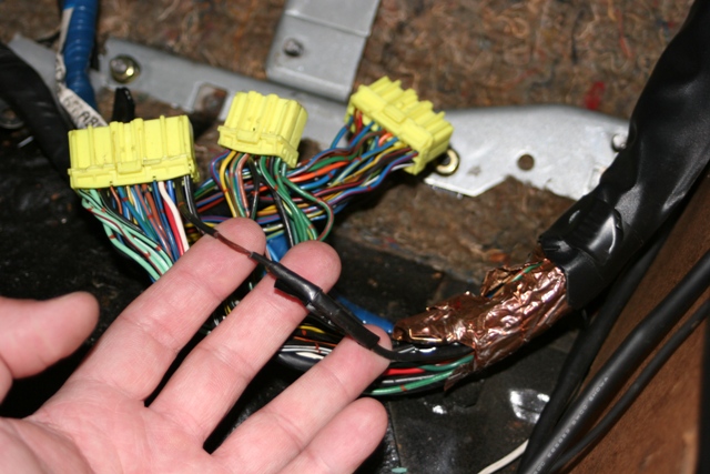
This shows the ground wire specified by the Apexi instructions. Notice that it has at some point been spliced. Would that be factory? The car has shown no signs of ever having been hacked at anywhere, even the factory radio was in it when we got it.
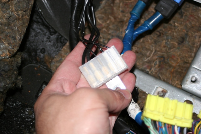
This image shows a big *** grounding block. This surprised me too because I've been through Aaron's grounding procedures and dont recall anything like this being mentioned.
Thanks!
Jim

HAILERS
Joined: May 2001
Posts: 20,563
Likes: 27
From: FORT WORTH, TEXAS,USA
I've a Zeitronix on a couple of series four.
I use the Power off the ECU to power the Zeitronix unit. I don't have or use a SAFC anymore. Using a RTEK2.1.
I've had no problems tapping the ECU power wire. And I doubt the SAFC pulls enough amperage to cause a problem
I depin the particular wire from the ECU plug, and solder the Zeitronix units wire on to the shank of the terminal and reinstall that wire in the ECU plug.
So, the RED Zeit wire, would go to the pin 1B.
For ground you use the BLACK Zeit wire, and I put a ring terminal on THAT wire and terminated it on one of the ECU Bracket studs.
The BROWN Zeit wire, should go to Brown/Black wire in the ECU plug. Pin 3C on S5 ECU plug. Soldered it as mentioned above.
Anyway, see the plug printout in the jpg I attached out of the SAFC manual for where the RPM and TPS wires go.
Those above wires are for basic operation. Three other wires on the Zeitronix plug are dedicated to a special Zeitronix boost sensor and only for that sensor.
Then there are a couple of other plugs for goofy footing around.
Pay attention to make sure you put the correct brown wire (pin 7 on the Zeitronix plug) in the ECU plug. The other brown wire is for the Zeitronix boost sensor.
I had a SAFC a few yrs ago. the Brown ground wires need to be soldered to the 3C wire as the Safc manual indicated. One will end up being closer to the ECU than the other. Sort of like.....use a razor blade and cut the insulation off the stock brown/black wire and solder on one of the SAFC brown wires.
I don't know if anything I write is applicable. Your going to doubling up on the TPS, POWER, RPM etc wires. I'm not sure how cumbersome that is going to be.
The SAFE people made the unit and should know how those two brown wires should be routed. I'd take their word for it.
EDIT: I just noticed, that on a series five ECU, both 3C and 3D are doing the same thing i.e. sensor ground for the ECU. So you could use one of those for the two brown wires of the SAFC and the other for the ZEITRONIX. The 3C is brown/black but the 3D is pure black.
Last edited by HAILERS; Nov 22, 2008 at 06:22 PM.
Cool. Thanks, Hailers.
You're a wiz with electronics. What possible difference would having one of the grounds 1cm closer to the plug than the other ground? I can't believe the ECU is fast enough that it would make any difference.
Good stuff though. Thanks again.
You're a wiz with electronics. What possible difference would having one of the grounds 1cm closer to the plug than the other ground? I can't believe the ECU is fast enough that it would make any difference.
Good stuff though. Thanks again.
HAILERS
Joined: May 2001
Posts: 20,563
Likes: 27
From: FORT WORTH, TEXAS,USA
I don't know where that 1cm came from. The SAFC manual? I looked and didn't see that written there.
When I had just a SAFC, I wired it like the SAFC manual picture ( jpg attached, I hope). The brown wire closer to the ECU. It worked fine. I don't remember measuring a thing for distance b/t the two.
When I had just a SAFC, I wired it like the SAFC manual picture ( jpg attached, I hope). The brown wire closer to the ECU. It worked fine. I don't remember measuring a thing for distance b/t the two.
Yeah, I didnt see anything written either about a 1CM stagger on the grounds except in the 1300 writeup. I think the "spacing" is just an illusion from the way they illustrated the wiring diagram. Otherwise, all of the wires would be staggered like in the illustration.
Thanks again
Thanks again
I found where the 1CM reference originates from. The SAFC II has a much more detailed installation manual than the Neo. Page 5 of the SAFC II installation manual specifies the 1CM. The Neo documentation doesnt mention it at all. In fact, the Neo instructions dont have much in the way of the installation instructions, just the car by car wiring diagrams.
I wonder if its just bad translations, sloppy work or the 1CM isnt needed anymore...
I wonder if its just bad translations, sloppy work or the 1CM isnt needed anymore...
Trending Topics
I called Apexi today. They still want the red/white to red and black to brown wires separated by 1CM even though they forgot to put that in the Neo manual. The guy said that there are two computers inside and they need the separation so they startup in the right order.
I provided links to the SAFC up above. Here are the Zeitronix ones.
If you look at the ECU pinout diagrams, the installs are very easy. The only thing to look out for is that you have to count pins/holes, NOT wires.
If you look at the ECU pinout diagrams, the installs are very easy. The only thing to look out for is that you have to count pins/holes, NOT wires.
