Is s4 alternator good enough for walbro225lph that is rewired
 03-18-14, 10:06 AM
#26
Question. ..When rewiring the pump to continuous 12v
1) do i have the choice of bypassing the fuel pump resistor and avoiding wiring anything to it ?
2) do I need to wire the resistor in somehow to make things all work?
Please help.ne understand all this so I can rewire my pump , I've seen two explanations...One says to power it with the stock relay another says u don't use it at all...I'm confused as to the reasoning behind both and which is better .
 03-18-14, 10:15 AM
#27
MECP Certified Installer
the simplified version still uses the stock fuel pump circuit but it is used to trigger the relay.
ie, when you crank the engine the AFM door opens, the fuel pump circuit triggers and feeds power to the pump. cut the wire to the pump and use the voltage supplied to power the coil circuit of the relay at pin 85, pin 86 wired to ground to complete the circuit to power the coil and trip the relay on. this bridges the contacts from 87 and 30 to feed power from the battery directly to the pump.
a relay has 2 basic halves, the coil and the bridge connection(contacts).
85 and 86 are for the coil, one needs 12v and the other needs ground to power up the coil and close the contacts in the relay. the bridged contacts simple allow voltage to pass through the relay(87 and 30, pin 87a will feed power from 87 out when the relay is not power on and shuts off that voltage when the relay is turned on. it is an auxiliary bridge for various purposes depending on if you need it or not. for the most part you can disregard pin 87a as it isn't used for many purposes but it can be used as a reverse switched power, ie battery power supplied to a device only when the relay is off).
the relay does not take much to trip on, so using the original wiring to trip the relay just makes life easier. it also allows you to retain stock functionality of the pump, meaning it won't run constantly with the key on.
the picture is only confusing if you read the yellow as a positive battery input, which it isn't it is a switched ground in the diagram. all we're doing is making the other pin 85(fuel pump 12v switched) do the switching and pin 86 is constantly grounded. since apparently the subaru forum i snagged it from supplies the pump with constant 12v and uses a switched ground to turn their pump on(opposite the FC).
this is the simplest i can describe:
87- fused battery wire
30- wired to pump (black/white wire on top of tank)
85- original wire leading to pump (chassis side of black/white wire)
86- ground
it's actually very simple, regardless of my jibberish.
86 = 12v
85 = ground
03-18-14, 04:14 PM
#29
it was based off of a generic bosch relay diagram in which polarity doesn't matter, 99% of 4/5 pin relays don't have a diode except for some OE applications.
if the relay came from something else, like a salvaged car and has a diode then simply reversing those 2 wires would fix it. an audible click should be heard when applying power/ground to either side of pins 85 and 86, if it clicks in both directions then there is no diode(unimportant in that event).
but still good to know for those who may come across the issue if they do grab a relay with a diode.
Last edited by RotaryEvolution; 03-18-14 at 04:17 PM.
03-18-14, 05:18 PM
#30
Question. ..When rewiring the pump to continuous 12v
1) do i have the choice of bypassing the fuel pump resistor and avoiding wiring anything to it ?
2) do I need to wire the resistor in somehow to make things all work?
Please help.ne understand all this so I can rewire my pump , I've seen two explanations...One says to power it with the stock relay another says u don't use it at all...I'm confused as to the reasoning behind both and which is better .
1) do i have the choice of bypassing the fuel pump resistor and avoiding wiring anything to it ?
2) do I need to wire the resistor in somehow to make things all work?
Please help.ne understand all this so I can rewire my pump , I've seen two explanations...One says to power it with the stock relay another says u don't use it at all...I'm confused as to the reasoning behind both and which is better .
In the stock setup, what part does the resistor pack play?
It varies voltage to the fuel pump for various reasons and to variable effect.
Now, in your proposed new set up what part would the resistor play?
Nothing, it's just a passthrough for ignition signal to the new fuel pump relay.
You could remove the resistor pack altogether and jumper the connector and get the same outcome at the new relay.
People probably keep the original system intact and wire as Ben suggests because it's easy and convenient, not because it's necessary or "better".
Is this a S4 or S5 chassis?
If it's an S5, I'm curious what you plan to do with the bulkhead connector on the tank.
You can bring all the current to that connector you want but it's going to be squeezed through woefully undersized pins.
03-18-14, 05:22 PM
#31
This is a series 4 turbo.
I'm a slow learner , I like to fully understand everything before diving into it, pictures/explanations usually help.
I appreciate all the replies.
Looks like using the stock relay to power it is probably best so the pump isn't constantly running when the key is turned to on.
I'm a slow learner , I like to fully understand everything before diving into it, pictures/explanations usually help.
I appreciate all the replies.
Looks like using the stock relay to power it is probably best so the pump isn't constantly running when the key is turned to on.
03-18-14, 05:30 PM
#32
just don't overthink it as clokker sais, it's painfully simple if you just follow all the instructions here. even the diode reference if the relay isn't turning over in the event you got a solid state/circuit protecting relay.
the multi step electrical system is bypassed and just acts as a trigger so i usually just leave it alone at that point in case you ever want to revert back for whatever reason as it is easily reversible. understanding electrical schematics probably makes this more simple to those who already know them, relays are extremely simple current control devices.
cut black/white wire between strut tower to pump, strut tower side of wire>pin 86 on relay
ground wire - mounted near the relay, there's a grounded point behind the carpet by the LR tail light> pin 85 on relay
that completes the control circuit of the relay
cut black/white wire pump side of wire>pin 87 on relay
battery wire +>30a fuse placed by the battery string out through the firewall below the clutch master, under the carpet to the rear of the car>pin 30 on relay
this completes the power feed circuit of the relay
the car should run how it did before but fuel pressure will be slightly higher due to the new 12v+ being constantly supplied. the 2 step system was just a bandaid for emissions, all modified turbo cars have it bypassed to maximize pump output and get rid of possible lower than expected voltages/pump output volumes.
Last edited by RotaryEvolution; 03-18-14 at 05:48 PM.
03-18-14, 05:46 PM
#33
I got a 30 amp relay from advance auto , id take a pic if I could find it. Lol
I'm just easily confused , do u have any pics of this setup ?
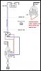
This is pretty much the schematic I've found here in this pic.
And this Is a 255 lph pump , I just messed up on the title.
I'll be doing this all pretty soon , just don't want to make any careless mistakes as its my first time doing it.
I'm planning on getting an aeromotive adjustable fpr here in the future to make the setup better and more bulletproof.
I'm just easily confused , do u have any pics of this setup ?
This is pretty much the schematic I've found here in this pic.
And this Is a 255 lph pump , I just messed up on the title.
I'll be doing this all pretty soon , just don't want to make any careless mistakes as its my first time doing it.
I'm planning on getting an aeromotive adjustable fpr here in the future to make the setup better and more bulletproof.
 03-18-14, 05:55 PM
#34
that schematic will work too, if that is easier to understand. i don't have any pictures on hand of the wiring.
in your schematic disregard the term "blue" and replace it with "black/white". why? because the fuel pump feed wire changes colors 3 times before actually reaching the pump so it is very confusing if you break it up into sections.
the fuel pump + positive wire is black/white between the top of the pump housing and the strut tower connector.
for reference though, the wire is 2 blue/white(they may be solid blue, its been a while) wires joined near the driver seat under the carpetting to a single wire leading to the LR strut tower from the LF kick panel. the jumper connector to the top of the tank from the strut tower connector is black/white, the wire inside the tank from the bulkhead to the pump itself is the "blue" wire you often see referenced in the FSM, Haynes and whatever manuals.
Last edited by RotaryEvolution; 03-18-14 at 06:01 PM.
03-21-14, 08:39 PM
#35
If i bypass the resistor box am I completely removing it ? I want to do.this the best way possible without having to mess with cutting wires om that resistor relay part if I don't have to...I just don't want to have the fuel pump turn on unless I turn the key to start the car.
Also how will my rtek deflood feature be affected, will it still work ?
Also how will my rtek deflood feature be affected, will it still work ?
03-21-14, 09:45 PM
#36
the rtek deflood only cuts the injectors off, not the pump.
if you want the easiest way then the methods i described will work, ignore the relays/resistor unless the pump for some reason fails to turn on later on due to a factory wiring issue. it's much less likely to ever happen though since the circuit is built to carry 15-20amps, but it's now only carrying .1amp. if the factory system ever fails then just bypass it and tap into the ECU itself, but i don't recall which wire it is that controls the 2 step relay for the fuel pump.
if you want the easiest way then the methods i described will work, ignore the relays/resistor unless the pump for some reason fails to turn on later on due to a factory wiring issue. it's much less likely to ever happen though since the circuit is built to carry 15-20amps, but it's now only carrying .1amp. if the factory system ever fails then just bypass it and tap into the ECU itself, but i don't recall which wire it is that controls the 2 step relay for the fuel pump.
 03-22-14, 10:10 PM
#39
So i got it all hooked up and working , I left the resistor there.
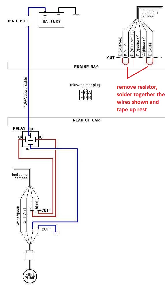
The only way to remove it is to jumper the wires as shown here ?
I'm hoping I'm running continuous 12v and it's not still working as a 9 to 12v switch since I haven't removed it
Car seems to run nice.
The only way to remove it is to jumper the wires as shown here ?
I'm hoping I'm running continuous 12v and it's not still working as a 9 to 12v switch since I haven't removed it
Car seems to run nice.

Thread
Thread Starter
Forum
Replies
Last Post
blkops
3rd Generation Specific (1993-2002)
7
08-12-15 01:30 PM