
Restoring Your Throttle Body: A Step by Step Guide of What it Takes.


Restoring Your Throttle Body: A Step by Step Guide of What it Takes.
Now that all these FC's are over the 20 year old mark, and some already at 25, keeping things in proper working order is far beyond the usual general maintenance. And the over complexity of the stock throttle body means more things to fail, plug up, or just not do their job. Worst of all, unsightly oxidized aluminum and rusty metal.
After a year of being frustrated with the spartan-like driveability of a stripped down, modded throttle body, I decided to go for an all original throttle body. I wanted to make certain everything was in perfect working order, so I went through it, and cleaned/refinished it along the way.
As many have said, modifying the throttle body is pointless on a street car, and it just shoots yourself in the foot. All the oem systems are there for a reason, and improve cold starts, idle, returning to idle, and smoothness upon sudden WOT.
So, lets get at it...
This is done on a series 4 Turbo II. Non turbo and S5 TII throttle bodies are much similar though.
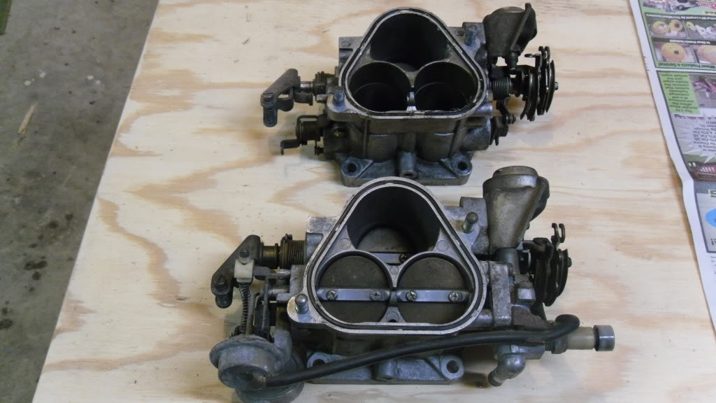
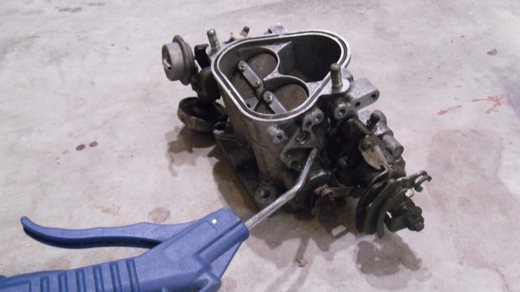
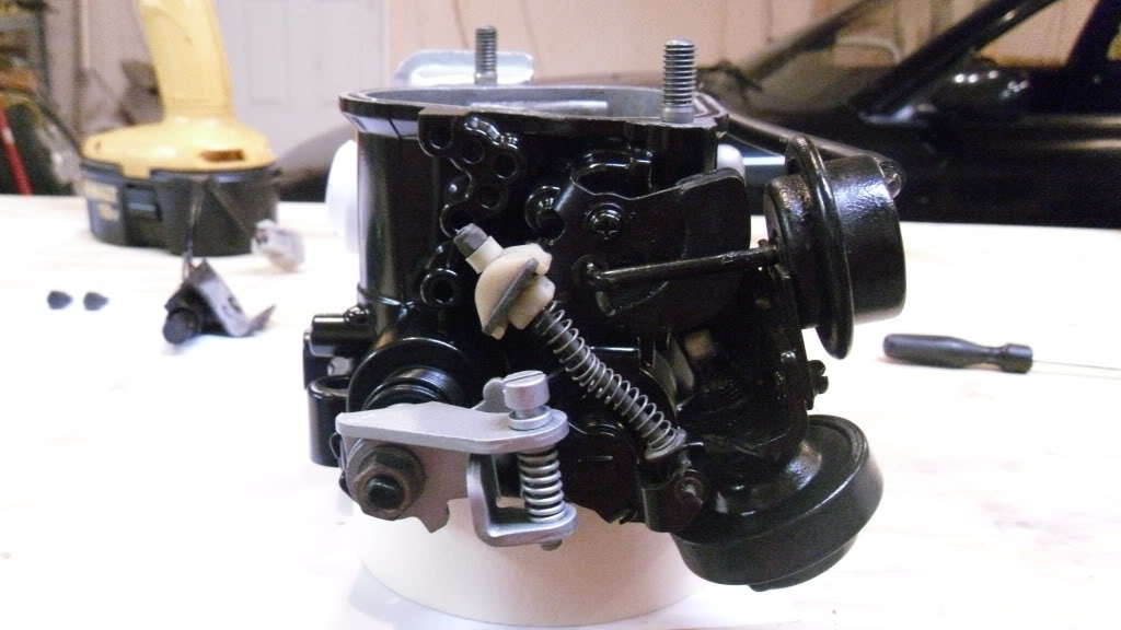
Heres a comparison of my old modified throttle body compared to the 'new' oem one.
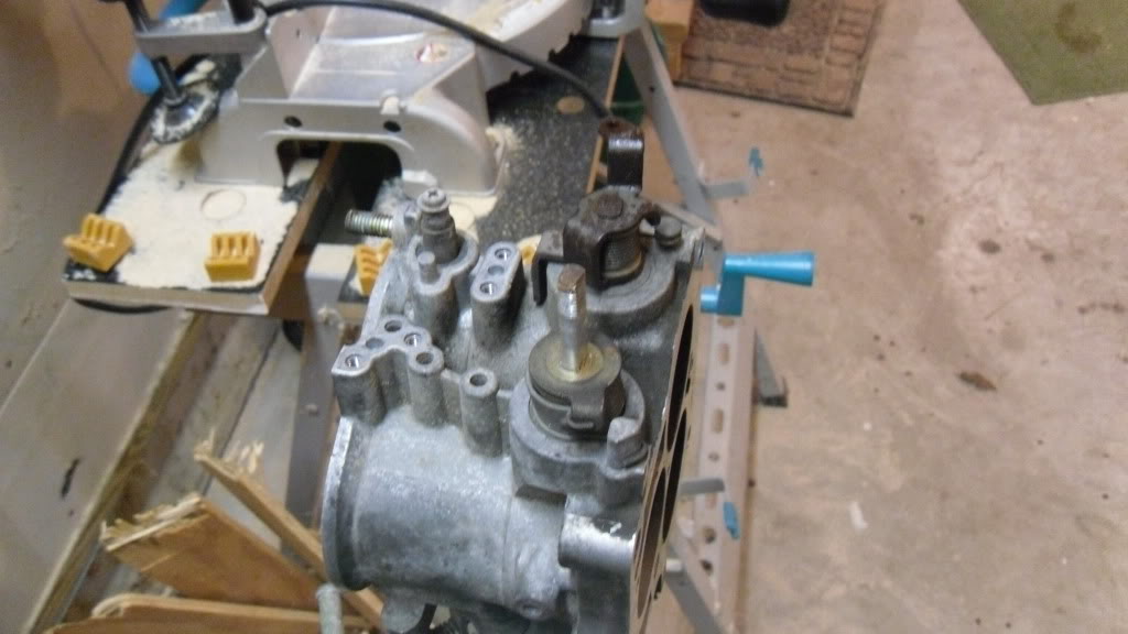
First thing I started with was removing the dashpot on the rear of the throttle body. The function of this is to slowly shut the throttle blades when you suddenly let off the accelerator. On this throttle body, it wasn't properly adjusted and was not touching the tab on the throttle shaft as it should be. Not good.
After removing the mount for the dashpot from the throttle body, loosen and remove the nut at the bottom, and unscrew the dashpot out of its mount.
Check that when the plastic tab at the bottom of the dashpot is pushed in, it slowly comes back out, it should take reasonable force to push it in. If not, replace it.
Next, remove the thermowax assembly. This controls a higher cold start idle, and it also keeps the second set of secondary blades shut when the engine is cold. Has nothing more than a temp activated vacuum switch which is connected to the vacuum diaphragm on the other side of the throttle body.
To test the thermowax, run hot water over it for a minute or two. The piston at the top should push out and extend a bit. It should contract back in when the thermowax cools.
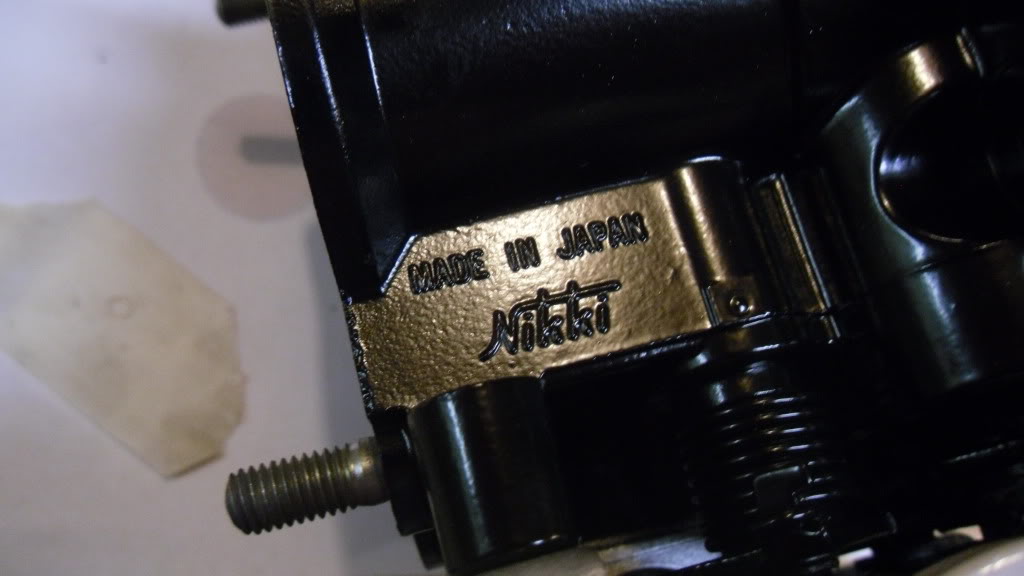
The back of the throttle body after the thermowax is removed.
Now make sure the coolant passages are clear inside the throttle body. Run water through the thermowax flange, and make sure it comes out the coolant line on top of the throttle body.
Mine was plugged. Blasted it with brake cleaner and compressed air, now it flows good.
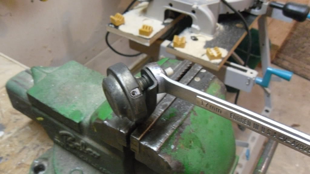
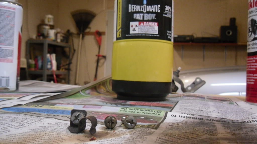
Some of these screws are seized in, so you'll need to heat them slightly, or you'll strip the heads out. I used a smaller torch, and heated lightly. This is aluminum, and it melts/deforms very easy, so be careful.
DO NOT THINK ABOUT HEATING ANYWHERE CLOSE TO THE DASHPOT! It doesn't take much at all to mess this up, luckily I had a good spare
My weapon of choice here:
Now remove the TPS if its still attached.
After a year of being frustrated with the spartan-like driveability of a stripped down, modded throttle body, I decided to go for an all original throttle body. I wanted to make certain everything was in perfect working order, so I went through it, and cleaned/refinished it along the way.
As many have said, modifying the throttle body is pointless on a street car, and it just shoots yourself in the foot. All the oem systems are there for a reason, and improve cold starts, idle, returning to idle, and smoothness upon sudden WOT.
So, lets get at it...
This is done on a series 4 Turbo II. Non turbo and S5 TII throttle bodies are much similar though.
Heres a comparison of my old modified throttle body compared to the 'new' oem one.
First thing I started with was removing the dashpot on the rear of the throttle body. The function of this is to slowly shut the throttle blades when you suddenly let off the accelerator. On this throttle body, it wasn't properly adjusted and was not touching the tab on the throttle shaft as it should be. Not good.
After removing the mount for the dashpot from the throttle body, loosen and remove the nut at the bottom, and unscrew the dashpot out of its mount.
Check that when the plastic tab at the bottom of the dashpot is pushed in, it slowly comes back out, it should take reasonable force to push it in. If not, replace it.
Next, remove the thermowax assembly. This controls a higher cold start idle, and it also keeps the second set of secondary blades shut when the engine is cold. Has nothing more than a temp activated vacuum switch which is connected to the vacuum diaphragm on the other side of the throttle body.
To test the thermowax, run hot water over it for a minute or two. The piston at the top should push out and extend a bit. It should contract back in when the thermowax cools.
The back of the throttle body after the thermowax is removed.
Now make sure the coolant passages are clear inside the throttle body. Run water through the thermowax flange, and make sure it comes out the coolant line on top of the throttle body.
Mine was plugged. Blasted it with brake cleaner and compressed air, now it flows good.
Some of these screws are seized in, so you'll need to heat them slightly, or you'll strip the heads out. I used a smaller torch, and heated lightly. This is aluminum, and it melts/deforms very easy, so be careful.
DO NOT THINK ABOUT HEATING ANYWHERE CLOSE TO THE DASHPOT! It doesn't take much at all to mess this up, luckily I had a good spare
My weapon of choice here:
Now remove the TPS if its still attached.
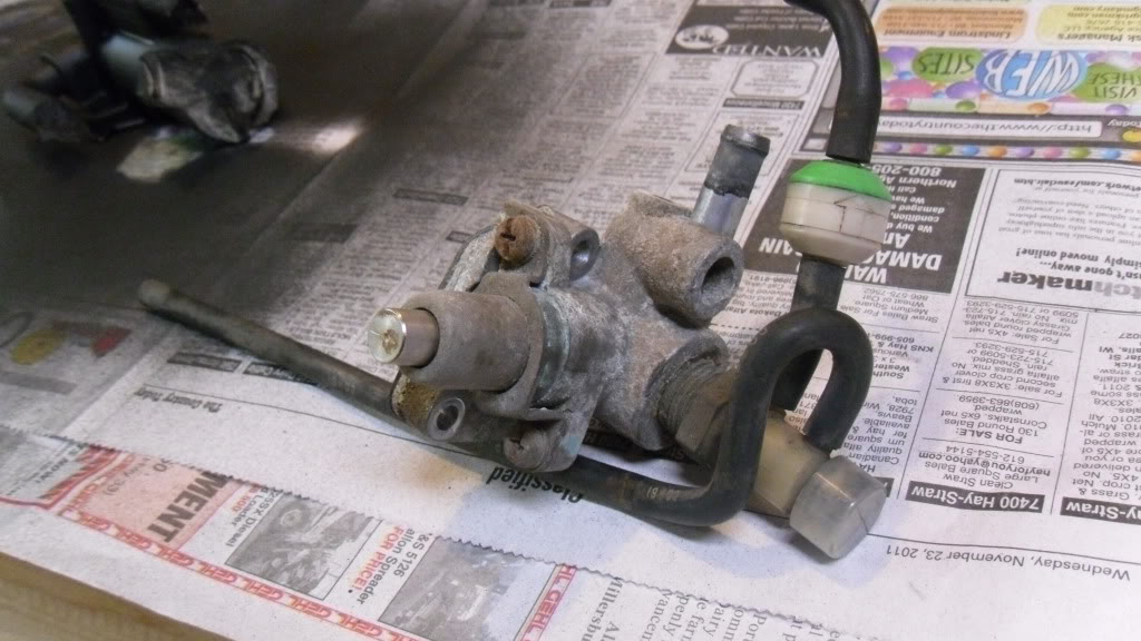
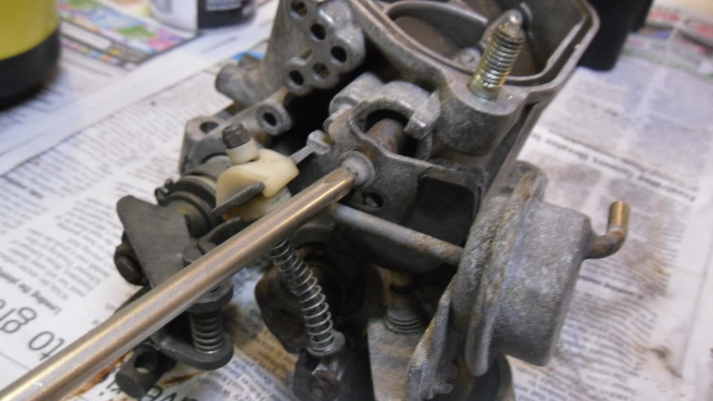
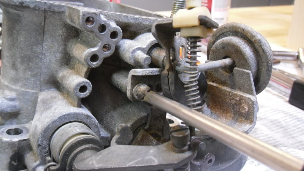
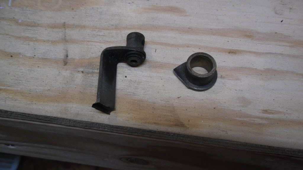
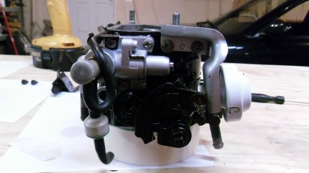
Now, to the other side to remove the double throttle system, as Mazda calls it. The purpose of this is to:
1. keep the no.2 blades from opening when the coolant temp is cold. It does this by the thermo-vacuum switch thing on the thermowax, which applies vacuum to the diaphragm on the double throttle system to limit throttle opening of the no. 2 set of secondary blades. When the rest of the throttle body is at WOT at that point, the no. 2 set of blades can't go too far, and instead the spring(shown in pics) compresses.
2.Slightly slows down the no.2 blades from opening suddenly during sudden WOT, which helps smooth the velocity of the incoming air. This works by a dashpot that pushes against a plastic cam(black in pics). When the dashpot causes resistance, the spring on linkage compresses slightly.
Now remove the screw that connects onto the shaft for the no.2 set of secondary throttle blades. This one took some patients to break loose.
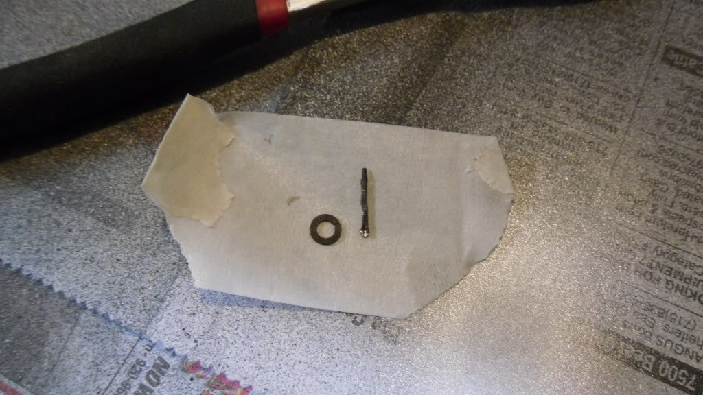
Remove the tiny cotter pin and washer from the sprung linkage that connects the shaft for the no.2 secondary blades to the shaft of the no.1 blades.
For tiny things I'm sure to loose otherwise, I find that sticking them to a piece of masking tape keeps them in place.
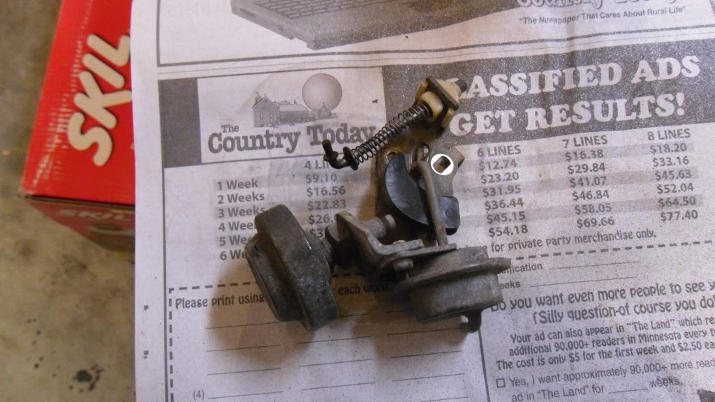
Now, I can manipulate the whole linkage over to the side to take the mounting screws out.
And the whole system removed as an assembly.
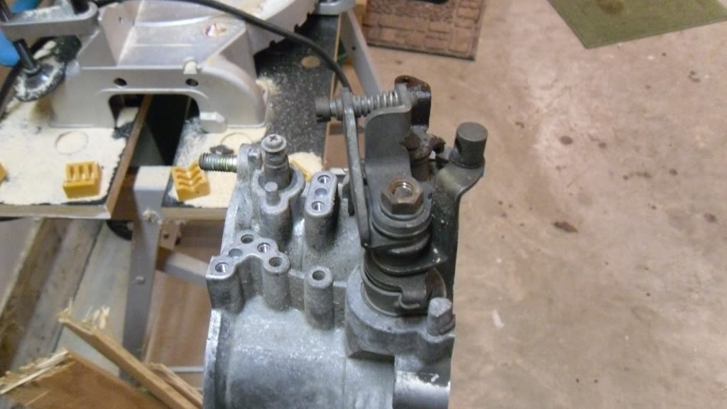
Make sure the dashpot pushes back out when you push the plastic tab in, and make sure the vacuum diaphragm holds vacuum.
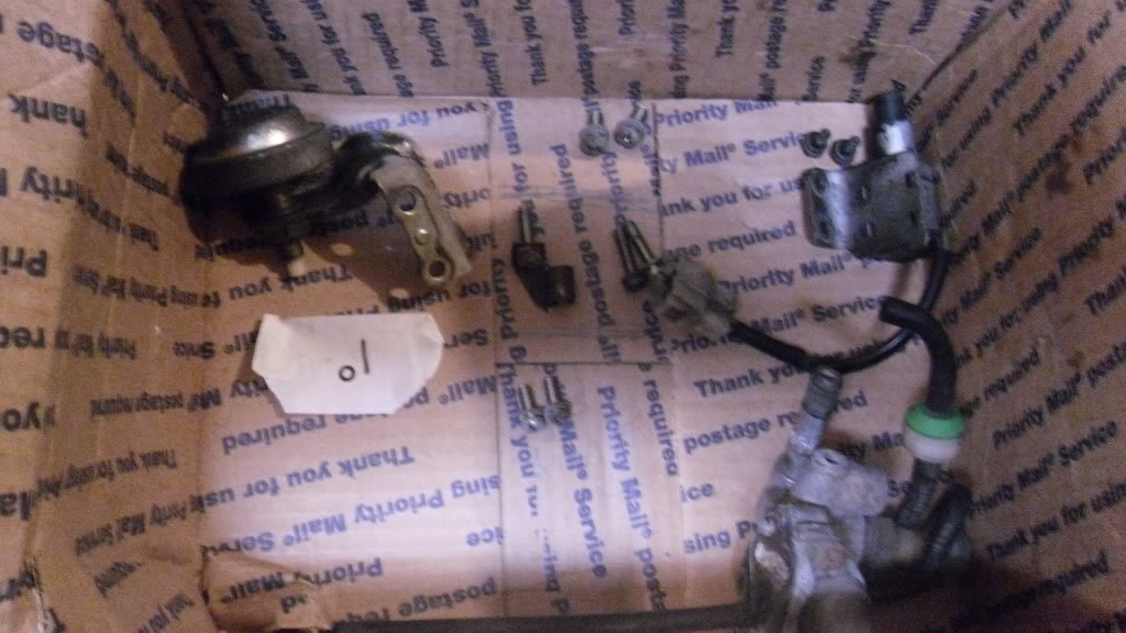
Also, its good to have some sort of an organization system for yourself.
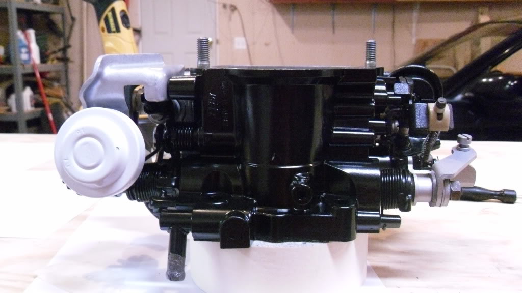
Now, I stripped down the throttle shaft on the front side. The front side comes apart 'relatively' simply. Remove the 12mm end nut, and take each piece off one at a time, placing them in order as you do so. There is really no need to do this, I just took it all apart to be able to clean it up better.
Being as I'm not going to ever run an oil metering pump, I cut the arm off the collar to which the omp rod attaches to on the throttle body. The collar needs to stay on the shaft for it all to go together properly though.
I chose not to take the other end of the throttle shaft apart(the side where the throttle cable attaches), due to the fact it contains multiple springs that when they come apart, chances are they won't go back together. I was able to still clean it all up pretty good, just took a bit more time.
Now its time to clean it all up. Clean some more. Clean the next day, the day after, and, you get the point. Once I had everything cleaned up good, I wirebrushed everything down. Obviously, do not wirebrush the plastics, the plastic tips of the dashpots, or the inside of the throttle body.
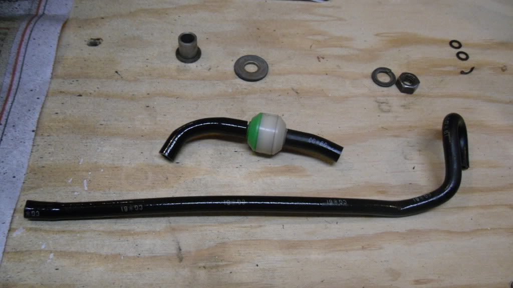
For the vacuum lines, they are a specially shaped piece, but I'm sure generic line would work if you needed to replace them. Mine were in good shape, just faded. So I hit them with some armor all. Also, make sure the one way check valve works properly(*non turbo guys, I don't think you have this).
Once everything is stripped down and cleaned up, time to break out the high heat paint!
Let it sit, then, reassembly is reverse of removal
Make sure you use some RTV(or I suppose the oem gasket, if you can get it) on the thermowax flange, because there is coolant flowing through there.
1. keep the no.2 blades from opening when the coolant temp is cold. It does this by the thermo-vacuum switch thing on the thermowax, which applies vacuum to the diaphragm on the double throttle system to limit throttle opening of the no. 2 set of secondary blades. When the rest of the throttle body is at WOT at that point, the no. 2 set of blades can't go too far, and instead the spring(shown in pics) compresses.
2.Slightly slows down the no.2 blades from opening suddenly during sudden WOT, which helps smooth the velocity of the incoming air. This works by a dashpot that pushes against a plastic cam(black in pics). When the dashpot causes resistance, the spring on linkage compresses slightly.
Now remove the screw that connects onto the shaft for the no.2 set of secondary throttle blades. This one took some patients to break loose.
Remove the tiny cotter pin and washer from the sprung linkage that connects the shaft for the no.2 secondary blades to the shaft of the no.1 blades.
For tiny things I'm sure to loose otherwise, I find that sticking them to a piece of masking tape keeps them in place.
Now, I can manipulate the whole linkage over to the side to take the mounting screws out.
And the whole system removed as an assembly.
Make sure the dashpot pushes back out when you push the plastic tab in, and make sure the vacuum diaphragm holds vacuum.
Also, its good to have some sort of an organization system for yourself.
Now, I stripped down the throttle shaft on the front side. The front side comes apart 'relatively' simply. Remove the 12mm end nut, and take each piece off one at a time, placing them in order as you do so. There is really no need to do this, I just took it all apart to be able to clean it up better.
Being as I'm not going to ever run an oil metering pump, I cut the arm off the collar to which the omp rod attaches to on the throttle body. The collar needs to stay on the shaft for it all to go together properly though.
I chose not to take the other end of the throttle shaft apart(the side where the throttle cable attaches), due to the fact it contains multiple springs that when they come apart, chances are they won't go back together. I was able to still clean it all up pretty good, just took a bit more time.
Now its time to clean it all up. Clean some more. Clean the next day, the day after, and, you get the point. Once I had everything cleaned up good, I wirebrushed everything down. Obviously, do not wirebrush the plastics, the plastic tips of the dashpots, or the inside of the throttle body.
For the vacuum lines, they are a specially shaped piece, but I'm sure generic line would work if you needed to replace them. Mine were in good shape, just faded. So I hit them with some armor all. Also, make sure the one way check valve works properly(*non turbo guys, I don't think you have this).
Once everything is stripped down and cleaned up, time to break out the high heat paint!
Let it sit, then, reassembly is reverse of removal
Make sure you use some RTV(or I suppose the oem gasket, if you can get it) on the thermowax flange, because there is coolant flowing through there.
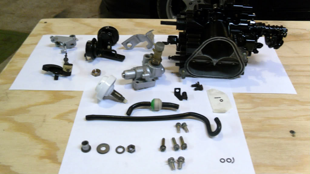
Ready for assembly:
And the finish product came out like this.
Just needs a TPS. I went to my hoard of TPS sensors for a known good one, as the one that was on there had cracks in the insulation near the base.
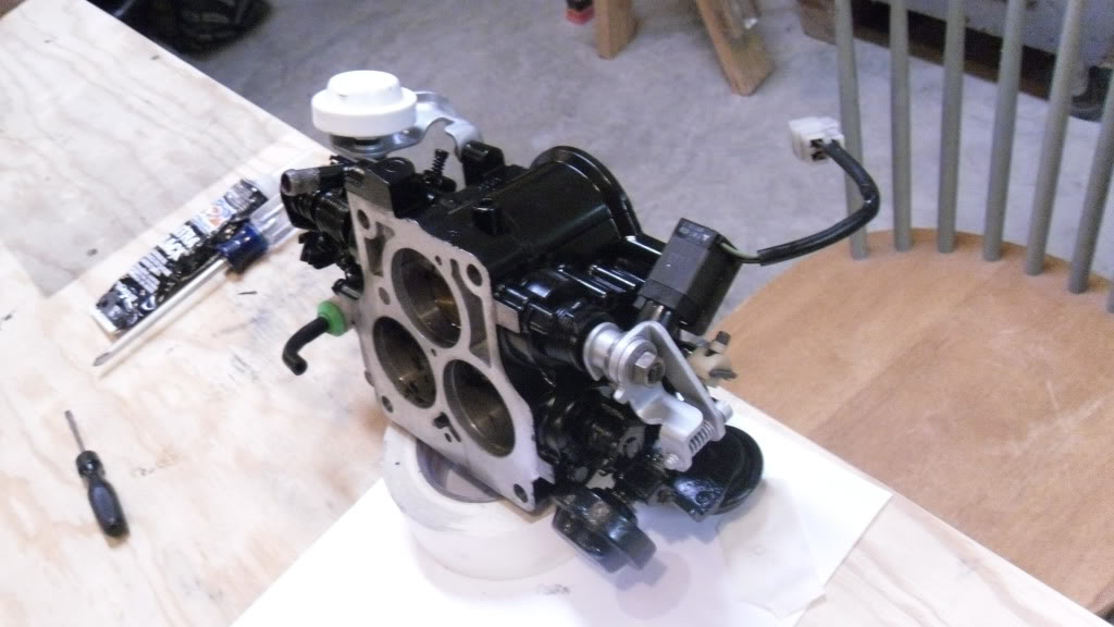
And its good to go!
Well I'm shot so this is only getting one tired proof read lol.
That pretty much finishes it. Hope this helps someone out at some point. If you have any questions at all, let me know
And the finish product came out like this.
Just needs a TPS. I went to my hoard of TPS sensors for a known good one, as the one that was on there had cracks in the insulation near the base.
And its good to go!
Well I'm shot so this is only getting one tired proof read lol.
That pretty much finishes it. Hope this helps someone out at some point. If you have any questions at all, let me know

nice work
Ive always hated how open and shut the engine gets when you take off the Double throttle, driving it at low rpm, its very noticable, but during racing, you wouldnt really care about it.
its hard to find an unmolested TB
Ive always hated how open and shut the engine gets when you take off the Double throttle, driving it at low rpm, its very noticable, but during racing, you wouldnt really care about it.
its hard to find an unmolested TB
Did you paint any of the silver pieces or is that just wirebrushed?
Originally, most of the linkage pieces were dipped/covered to retard oxidation, if you've wire brushed the finish off, all those pieces/hardware will rust like crazy.
Very nice looking though, I know how hard it is to clean a throttle body and can appreciate your effort.
Originally, most of the linkage pieces were dipped/covered to retard oxidation, if you've wire brushed the finish off, all those pieces/hardware will rust like crazy.
Very nice looking though, I know how hard it is to clean a throttle body and can appreciate your effort.


Trending Topics
In addition, I'd really recommend another step.
Once the body is totally stripped (your fear of the primary throttle plate is unfounded...it looks worse than it is and since you were smart enough to get that far, you'd have handled that last step), if at all possible, ultrasound it.
Nothing will clean the little nooks/crannies and internal passages like ultrasound will.
But, you say, I have no ultrasound tank...so thanks for nothing!
First of all, you're welcome.
Secondly, if you're near any sort of metropolitan area, lots of places have tanks and given the economy are more amenable to piecework like this. Fab shops and specialty welders are likely targets.
Surprisingly, so are clock repair shops (my nic isn't totally random).
As for color...
The black part looks cool as hell but Rob's choice of silver might be a better choice in the long run. Water spots and dust show more on shiny black as will any errant screwdriver slips.
A scratch in the silver paint just exposes more "silver".
Finally, I'd replace all the hardware with stainless and use antiseize during assembly.
The next person to work on this won't need a torch.
Clokker,
I was just browsing the net because you mentioned the ultrasonic cleaning. There are some DIYs you can use to make your own. It basically includes taking a palm sander, metal can, insulating the unit off the ground with foam. Then fill it with whatever you like + water/cleaning solution.
probably not 100% effective, but it wouldnt hurt if you got the stuff laying around!
if there was a part i would strongly recommend powder coating while it's disassembled, this would be it. takes hours to do all the work stripping it down, best to make sure it looks good for a good long time afterwards.
unfortunately you have to take a few more steps removing the seals and butterfly mechanisms as well as they can't take the 400-450F heat. but then that allows you to scrub the throats down nice and good, the buildup in there and on the butterflies does affect the idle.
unfortunately you have to take a few more steps removing the seals and butterfly mechanisms as well as they can't take the 400-450F heat. but then that allows you to scrub the throats down nice and good, the buildup in there and on the butterflies does affect the idle.
Last edited by RotaryEvolution; Dec 6, 2011 at 09:28 AM.
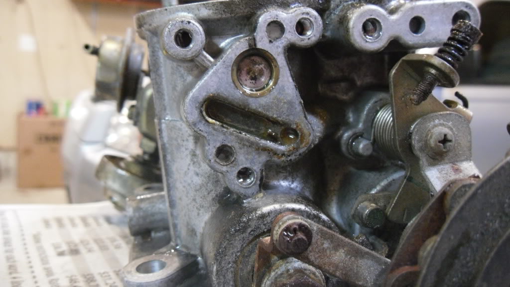
the throttle body actually has a metered leak where the thermowax sits on the throttle body, if you look at the casting in the 4th picture you can see it. i use a block off plate and JB weld on it for higher HP boosted applications as the leak is rather annoying to test the rest of the system for leaks with it hissing away back there. for true performance builds a pressure test is a must.
Yes, we struggled with that "metered leak" three years ago. IIRC you were on hiatus in '08.
Yes, we struggled with that "metered leak" three years ago. IIRC you were on hiatus in '08.
i was probably fighting the machine shop to get the dowel pinning machine work setup for Nile's pettit race motor rebuild. took them 3 weeks, and is why i now do it in house.
the throttle body actually has a metered leak where the thermowax sits on the throttle body, if you look at the casting in the 4th picture you can see it. i use a block off plate and JB weld on it for higher HP boosted applications as the leak is rather annoying to test the rest of the system for leaks with it hissing away back there. for true performance builds a pressure test is a must.
i honestly don't even know why they put it there. i have run mine blocked off for some time and haven't noticed any ill effects. i can only assume they figured it would put sideways pressure on the rod and wear the butterflies. sometimes engineers tend to overthink things.
i noticed that leak also when I was pressure testing my intake system. I would hear this leak around the TB. I had to use a little bit of silicone to cover it, and pressure test again and it didnt leak no more. Car drove the same way before and after.
it is rather minor for stock boost levels, at 20+PSI though it sounds like a train back there. depends how worn the shaft is as well i suppose, my TII has 211k on it so i'm sure it has seen better days but that throttle body is gone now replaced with a lower mile unit.
very cool.. i might do this since i have nothing else to do.. already ported/ shaved my tb a few years back, might as well clean it all up and throw a nice simple coat of silver on it as well.
