
pressure sensor problem in T2 swap

so i just finished a T2 swap into my FC and i'm getting a code 7, Boost/Pressure sensor failure. at the 4 pin connector i have 12V, 12V, 5V, and ground. i've been told that the alt wire from the gauge cluster backfeeds into one of the wires and that's why i have 2 12V wires instead of one. any ideas?
86 Base model FC
90 JDM motor
N333 ECU
88 T2 wiring harness with factory high impedence injectors (the odd ball year)
318 pressure sensor
86 Base model FC
90 JDM motor
N333 ECU
88 T2 wiring harness with factory high impedence injectors (the odd ball year)
318 pressure sensor

Full Member
Joined: Oct 2008
Posts: 55
Likes: 0
From: Oregon
hey bud i live in harrisburg oregon  not far from you should add each other as friends.... i dont know enough about rx7s yet to be able to answer that question but i will keep my eye out for anything that might help
not far from you should add each other as friends.... i dont know enough about rx7s yet to be able to answer that question but i will keep my eye out for anything that might help


There are four wires on the 88 turbo pressure sensor and harness. Note that a couple wire colors are different from the 86-87 1/2 build date cars.
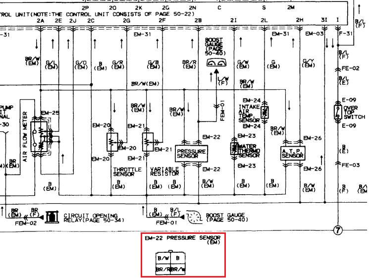
Br/R --> ECU pin 2B, ECU signal voltage with gauge signal tapped into it
Br/W --> ECU pin 2A, reference voltage
B --> ECU pins 2C/3A, main EFI ground wires under the UIM
B/W --> +12V fed by the main relay
all that info is available in the S4 wiring diagrams (page 50-25) and the ECU pinout in the fuel and emissions control section of the S4 FSM, pages 4B-31 through 4B-33. Please read the wiring diagrams, the first 10 pages or so explain what all the abbreviations and other symbols mean.

HAILERS
Joined: May 2001
Posts: 20,563
Likes: 27
From: FORT WORTH, TEXAS,USA
Awwwwww, man, you used a TURBOII EM harness on a non turbo car. THAT is your problem.
TURBOII EM harness do not match the wires in the non turbo FRONT harness. I'm talking about the two ORANGE in color plugs on the EM harness that mate with the FRONT (non turbo) harness.
Not only are you backfeeding batt voltage into the boost sensor, your back feeding batt voltage into the pin 2B of the ECU. A pin that should never see more than 5vdc and actually never even see that much voltage. MOre like 2-3vdc is normal.
So you go to the ORANGE plug that carrys the brown/red wire and cut it. Then put a end cap on it so it does not touch anything. I forget what else you have to do. Do to using the TURBOII EM harness it meas you lose your water temp, oil temp signals and other things. Repinning of the ORANGE plugs can correct that.
Plus you don't have wires to the alternator now either 'cause the TURBOII EM harness does not carry alt wiring like the non turbo EM harenss does.
HAILERS
Joined: May 2001
Posts: 20,563
Likes: 27
From: FORT WORTH, TEXAS,USA
Anyway, the B/W on the non turbo FRONT hareness is feeding the BR/R wire on the TURBO EM harness and that is backfeeding the BR/R wire on the boost sensor AND the pin 2B of the ECU. NOT DESIRABLE.
The B/W wire on the non turbo Front harness goes to the ENGINE fuse which in turn gets fed thru the Main Relay when the key is ON or better.
The W/B wire in the non turbo Front harness is now tied to the Black wire in the TURBO EM harness. The W/B comes from the alternator relay in the CPU. So it seems to me since that is so, all the warning lights on the dash would come on ALL the time. What with the BLACK wire being a ground wire in the turbo EM harness. Ugggh.
So I attached the plugs FEM-01 and FEM-02 for TURBO and NON TURBO cars below. Look at the wire colors in the plugs. Ain't the same in all places. Things have got to be moved around a bit.
See wiring diagrams.
HAILERS
Joined: May 2001
Posts: 20,563
Likes: 27
From: FORT WORTH, TEXAS,USA
So if you cut the BR/R wire at the EM side of the plug at FEM-01, the boost sensor output should be ok again. Plus cut the B wire just below it on the FEM-01 plug. You can deal with the other wires at another time.
Trending Topics
wow Hailers, wish i would have looked at this sooner. i figured out what wire was causing my problems by just looking at the FSM for hours and then doing a lot of testing with my DMM (digital multi meter). and your right, half my gauge cluster doesn't work, not that it really matters as i use Autometer gauges for oil psi, water temp, and boost/vac. but i am very interested in re-pining the ecu to make them work again. i've gotten pretty good at it in the last 2 or 3 days.
so is my computer not seeing some of the major signals it needs to see to have it running correctly by not having an NA wiring harness? it runs good minus the small vac leak i have somewhere.
so is my computer not seeing some of the major signals it needs to see to have it running correctly by not having an NA wiring harness? it runs good minus the small vac leak i have somewhere.
oh, and this is more of a race/drift/autocross car with occasionaly DDing so things like subzero start, ps, automatic inhibit switch and all that aren't important to me. if it were more of a DD i'd want most of that i suppose. no PS either.
HAILERS
Joined: May 2001
Posts: 20,563
Likes: 27
From: FORT WORTH, TEXAS,USA
Naw. Just cut the brown/red wire at the EM side of FEM-01 and leave it at that. Might cut the black wire directly below it while you there. Cap off the cut ends so they don't touch anything.
ECU controls non of the gauges but the signal for the water gauge runs thru the FEM-01 and FEM-02. Since you used a turboii EM harness that Y/W wire from the water temp sensor is in the FEM-01 but the rest of the path TO the guauge is the Y/B wire in FEM-02 (the FRONT side of that plug). So you'd have to make them connect together some way for the guage to work.
Just look at the last jpg I attached in the post above. In the TURBO plug FEM-01 you'll see a Y/W in the EM half of that plug. Then look at the NON TURBO FEM-02 plug and at the FRONT side of that plug where you'll see a Y/B wire. Those two wires have to mate for the water temp gauge to work.
The wires I labled as the wires that let the ECU know the key is put to START let the ECU go into it's START FUEL MAP during starting and makes for a better start of the engine when it's cold....and hot sometimes I suppose. They end up at pin 3B of the ECU.
Neither oil nor tach nor voltage or fuel gauge signals go thru the EM harness on the engine.
sweet, thanks for the info i'll rewire it soon and see if it makes more of a difference. it does take a long time to start when it's cold i've noticed. anything else i should know about using the harnesses that i used?
into the factory plug, it's still a S4 harness so i'm assuming that it's going to the dash and ignition switch. it still runs good and is keeping the battery charged, lights lit and everything going. is there something i'm missing?
also, the wire that lets the ecu know the key is in the on position is in the same socket on both plugs, it's B/R for the NA and B/W for the turbo so i shouldn't need to touch that since it's all the same, minus a color difference. or is the X you put in the socket where i need to put the B/W wire from my turbo harness?
also, the wire that lets the ecu know the key is in the on position is in the same socket on both plugs, it's B/R for the NA and B/W for the turbo so i shouldn't need to touch that since it's all the same, minus a color difference. or is the X you put in the socket where i need to put the B/W wire from my turbo harness?
HAILERS
Joined: May 2001
Posts: 20,563
Likes: 27
From: FORT WORTH, TEXAS,USA
Yeah, there's something I'm not understanding.
The wires for the alternator on a series four non turbo are in the EM harness. The EM harness is the one attached to the engine. Fuel injectors and the like.
The wires for the alternator on a TURBO series four car are in the Engine harness. The engine harness being the one on the left side of the engine bay having the CAS plug on it/batt terminals/starter wires/oil pressure sensor/oil level sensor etc.
Sooooooooo, how can your alternator be connected up if you have a TurboII EM harness on the engine? Since the small alt plug does not exist on a TURBO EM harness. I'm lost on that.
The alternator plugs on both type harness have a B/W and a W/B wire.
See jpgs attached for what I mean about the plugs for the alt being on seperate hareness for non turbo vs turbo cars.
And yeah, the wires to 3B are ok. Just too many BR wires must have confused me.
my alt plug has a large B/W and a smaller BR/Y wire, is this the wrong plug? i noticed that my NA harness had the plug with the emissions plug and the turbo harness had what i "thought" was the alt plug mixed in with the primary injectors.
also, the wire that i de-pinned to stop the 12V's from backfeeding into the pressure sensor is black with a white stripe and red dots. the car isn't throwing any codes. this is a S4.5 harness though so i imagine not all the wire colors will be the same. which i know doesn't explain the alt wiring either. this harness came out of a 1988 T2 with ABS and high impedience injectors but was still clearly an S4 exterior, interior and engine. is the alt wire on a S5 T2 wiring harness in the EM harness? maybe that would explain it?
also, the wire that i de-pinned to stop the 12V's from backfeeding into the pressure sensor is black with a white stripe and red dots. the car isn't throwing any codes. this is a S4.5 harness though so i imagine not all the wire colors will be the same. which i know doesn't explain the alt wiring either. this harness came out of a 1988 T2 with ABS and high impedience injectors but was still clearly an S4 exterior, interior and engine. is the alt wire on a S5 T2 wiring harness in the EM harness? maybe that would explain it?
Last edited by leftcoastdrifter; Oct 22, 2009 at 12:32 AM. Reason: add stuff
HAILERS
Joined: May 2001
Posts: 20,563
Likes: 27
From: FORT WORTH, TEXAS,USA
That plug is for the airbypass solenoid. The one with BW/BY.
The Orange plug called FEM-01 has fifteen pins/sockets and not to be confused with the thirteen pin plug colored orange named FEM-02
The Orange plug called FEM-01 has fifteen pins/sockets and not to be confused with the thirteen pin plug colored orange named FEM-02
HAILERS
Joined: May 2001
Posts: 20,563
Likes: 27
From: FORT WORTH, TEXAS,USA
These two orange plugs are located in the passengers foot well and up and to the the far right of that area. One half of each plug is a part of the EM harness on the engine and the other half of the plugs are a part of the Front harness. In this case the Front harness side is non turbo and the EM half is Turbo.
86-88 non turbo wires should be the same and 86-88 Turbo wire colors should be the same with small exceptions like some gnd wires in a 86-87 will be Br/B and in the 88 will be pure black instead.
FEM-01 is orange in color and has fifteen pins/sockets. FEM-02 is orange in color and has thirteen pins/sockets.
so basically i need to wire in my own alt wires correct? take out the BR/R and B wires on the EM harness on connector FEM-01 and match them up to my new wires i made coming from my alt into the now vacant pins. this will attach the new wires to the NA's F harness. but will these end up in the alt wiring on the ecu? if not, do you know where i can find a pin out of a N333? i'll just wire it directly to the ECU and bybass my connectors.
HAILERS
Joined: May 2001
Posts: 20,563
Likes: 27
From: FORT WORTH, TEXAS,USA
There's no input to the ECU from the alternator.
The two ORANGE in color plugs called FEM-01 and FEM-02 are connectors that connect the Front harness to the Emissions harness and the wires don't nessasarily go to or from the ECU (such as wiper wires/cruise wires).
The top wire on the alternator was originally B/W and should go to the FEM-01 plug (fifteen pin/socket plug) where your turbo EM hareness had a BR/R wire. It will mate with a B/W wire in the non turbo front harness.
And the lower wire in the alternator plug will go to FEM-01 and go where there was a pure Black wire and mate with a W/B wire in the non turbo FEM-01 harness plug.

Thread
Thread Starter
Forum
Replies
Last Post
trickster
2nd Generation Specific (1986-1992)
25
Jul 1, 2023 04:40 PM
stickmantijuana
20B Forum
8
Aug 18, 2015 02:46 PM