
pics of a fuel pump rewire?

Thread Starter
Joined: Feb 2005
Posts: 1,933
Likes: 0
From: OrangePark FL
pics of a fuel pump rewire?
tried looking in the archives and basic search around the site, I found the diagram to use for a fuel pump rewire on a s4 t2 but the one thread that used to have pics now all the links are dead  does anyone have any pics of how they did it and how it turned out?
does anyone have any pics of how they did it and how it turned out?
Joined: Sep 2005
Posts: 25,581
Likes: 136
From: Smiths Falls.(near Ottawa!.Mapquest IT!)
just a tid bit of info: you don't need to do that if you have a N/A based car and swapped to TII.
The N/A car has no resistor in the pump wiring.
The N/A car has no resistor in the pump wiring.
what fuel pump, injector and tubo are you running ?
beause i will suggest a 20A fuse and 10g wiring from the pump to the relay and the relay to the battery 12v
you will only find this out when u go from 70% duty cycle to 100% duty cyle in heartbeat and you crack a plate
beause i will suggest a 20A fuse and 10g wiring from the pump to the relay and the relay to the battery 12v
you will only find this out when u go from 70% duty cycle to 100% duty cyle in heartbeat and you crack a plate
Thread Starter
Joined: Feb 2005
Posts: 1,933
Likes: 0
From: OrangePark FL
ok? im running a supra pump with stock primarys and id 750 secondarys
just to be clear, im looking for pics of someone who has done a fuel pump rewire
just to be clear, im looking for pics of someone who has done a fuel pump rewire
Last edited by Nick_d_TII; May 3, 2016 at 12:28 PM.
Trending Topics

Thread Starter
Joined: Feb 2005
Posts: 1,933
Likes: 0
From: OrangePark FL
ok now im slightly confused, every diagram shows putting in a relay while Nick d TII has a straight line from the plug under the dash to the plug at the pump.
which is the better/correct thing to do?
Calling the all knowing satch to maybe lend some knowledge
which is the better/correct thing to do?
Calling the all knowing satch to maybe lend some knowledge


did this on my old s4 t2 setup. now i rewired the car to s5, but seems like the rectangular 4-pin connector is the same.
As above said, you need to run a bigger gauge wire from battery to fuel pump. Only way around this is if you have battery relocated to trunk as I do so I only have a 2-foot lead from battery to fuel pump.
Where the fuel pump's harness meets the chassis harness, I unplugged the connector and on the fuel pump harness side, I hooked up factory fuel pump power black/white (s5, not sure if s4 is the same) on connector side to relay. Then have power going through the relay from battery and power coming out of the relay to power the fuel pump goes to fuel pump harness on the fuel pump side. I feel as if there is a better way than what I did as in actually replacing the whole power wire going to the fuel pump, but I haven't done the math on wiring gauge/amps, and I just needed a small boost.
Wired the same way on my old s4 t2 setup for years, helped tremendously in increasing fuel pressure with stock FPR, and richened up AFR's.


Senior Member

Joined: Apr 2009
Posts: 606
Likes: 80
From: netherlands
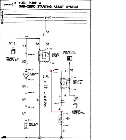
This is what I did on my '91 (until I changed the whole fuel setup with flip switches and ****)
It's mainly a diagram on how to remove the resistor relay.
Note: I had the battery in the back what made it easier for me to run a new 12v wire.

big version click here
oh! almost forgot!
I had cut the connector from the resistor relay, and used that to get the wires connector as shown on the diagram.

It's mainly a diagram on how to remove the resistor relay.
Note: I had the battery in the back what made it easier for me to run a new 12v wire.
big version click here
oh! almost forgot!
I had cut the connector from the resistor relay, and used that to get the wires connector as shown on the diagram.
Last edited by GeenIdee; May 23, 2016 at 03:22 PM.
If someone posted a pic of two wires soldered together how do you know the solder is a good solder and not a cold solder. I think you're making way too much of the pics of the job done because it should look exactly like it does in the diagram.

Thread
Thread Starter
Forum
Replies
Last Post
wallyrx7
1st Generation Specific (1979-1985)
4
May 16, 2016 08:59 AM
Valkyrie
3rd Generation Specific (1993-2002)
20
May 6, 2016 10:18 PM
jza80
Power FC Forum
1
May 2, 2016 06:50 PM