
Fuel pump rewire: this look good?

Fuel pump rewire: this look good?
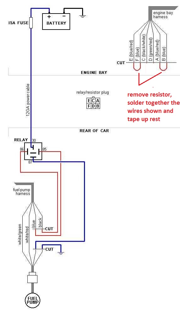
Just wanted to run something by you. I found this on my hard drive downloaded from here but I can't remember what post it comes from. Does it look about right for rewiring the fuel pump?


Many prefer the simplicity of eliminating the fuel pump resistor. This may result in a richer idle, but if you have an adjustable fuel pressure regulator or a means to tune the computer you can mitigate that.
Have you verified that your pump voltage is low or something? Are you Turbo'd? Why are you rewiring it?
The diagram also adds an additional relay and wiring to the system. IMO, most of this unnecessary, unless your running good amount of boost and aftermarket pump(s). Personally, I didn't/wouldn't rewire my car that way. It will probably work, but the voltage to the coil in the relay is going to be getting WAY more voltage/amperage than it needs and could possibly fail.
Good luck though.
Rewiring because everything else checks out ok and I'm only getting just over 5V to the fuel pump.
Got it hooked up this way and the voltage to the pump is a lot better. Is an adjustable FPR an easy thing for these cars? May seem a silly question, but the stock one seems pressed into the fuel rail so wouldn't be easy to remove from the system. Or am I thinking about it the wrong way?
Trending Topics
But higher fuel pressure does not only provide more fuel, also the spray is better which also helps in better combustion...
But i would recommend a fpr anyways, i had detonating issues with stock fuel pressure when i started to upgrade.
S5
Sorry for being dumb but are you saying the higher fuel pressure will cause better spray and combustion? If so I'd have thought that would decrease detonation issues.
Sorry for being dumb but are you saying the higher fuel pressure will cause better spray and combustion? If so I'd have thought that would decrease detonation issues.
Sorry to bump this thread from the dead, but does anyone know if the modified diagram arghx posted still retains the safety feature where the pump will shut off in a crash/rollover?
Im running a large streetport and an FD pump and have noticed AFR's have been eerily lean. (14-15) under load.
Measure my voltage between the blue and black at the fuel pump connector and im seeing 7~8.2v at idle and 8.7 under load smh....
Im running a large streetport and an FD pump and have noticed AFR's have been eerily lean. (14-15) under load.
Measure my voltage between the blue and black at the fuel pump connector and im seeing 7~8.2v at idle and 8.7 under load smh....

a) you don't necessarily need to bypass the resistor relay by the RF headlight, just use the original power wire to the pump to turn on the relay.
and
b) if you have an S5 and are using an upgraded pump you should bypass the OEM bulkhead connector.
and
b) if you have an S5 and are using an upgraded pump you should bypass the OEM bulkhead connector.
ok understood. makes sense. im running an S4 fwiw.
so just for clarification, either methods work just fine, just one retains the resistor to lower voltage to 9v and the other is if you want to do without.
now maybe im being ocd but is that a 5 pin relay in the diagram or a 4 pin with just a random line unused line in the center?
so just for clarification, either methods work just fine, just one retains the resistor to lower voltage to 9v and the other is if you want to do without.
now maybe im being ocd but is that a 5 pin relay in the diagram or a 4 pin with just a random line unused line in the center?
More recirculation increases HC vapor emissions as hot fuel returns to the tank. Removing the resistor also increases fuel pump noise. While those are lesser concerns for many of us, there is a chance that idle AFR will become richer without some other measure being taken.
Bringing back an old thread so I don't have to make a new one.
Can anyone tell me the location of the harness in the engine bay that needs to be cut to bypass the resistor? I am about to rewire my fuel pump according to the diagram (taking Elwood's advice into consideration).
And just to be clear, I will be adding the relay, not using the factory relay. Is this correct?
MECP Certified Installer
Joined: Feb 2009
Posts: 3,176
Likes: 3
From: Mesquite, TX-DFW
Bringing back an old thread so I don't have to make a new one.
Can anyone tell me the location of the harness in the engine bay that needs to be cut to bypass the resistor? I am about to rewire my fuel pump according to the diagram (taking Elwood's advice into consideration).
And just to be clear, I will be adding the relay, not using the factory relay. Is this correct?
Can anyone tell me the location of the harness in the engine bay that needs to be cut to bypass the resistor? I am about to rewire my fuel pump according to the diagram (taking Elwood's advice into consideration).
And just to be clear, I will be adding the relay, not using the factory relay. Is this correct?
And yes, elwood is correct. Pin 86 should receive 12v and 85 ground, not the other way around.
MECP Certified Installer
Joined: Feb 2009
Posts: 3,176
Likes: 3
From: Mesquite, TX-DFW
You are welcome and by the way...
I personally have no issues with the factory relay, and find that adding another one is simply redundant.
EDIT: also I want to mention, instead of running **** to the battery, there are very large 12v fused wires at the ignition switch. I will never understand why people run wire to the positive battery post (audio amplifiers excluded). You have huge 12v positive wires at the ignition switch that are already fused and are located in an inconspicuous location!
I'll keep that in mind. What does it take to get to the ignition switch? My S4 has a mostly mint condition dash, and I'm afraid of things disintegrating if I try to remove anything.
MECP Certified Installer
Joined: Feb 2009
Posts: 3,176
Likes: 3
From: Mesquite, TX-DFW
The ignition switch has a long harness coming from it, which then connects to the car via a molex connector. You DO want to connect wires on the car side of that molex connector, or you will hate yourself if you ever need to replace the ignition switch.
If I remember correctly, there is a big Black/Green wire that is 12v constant.