
Pic request for Emission Removal S4 TII

Thread Starter
Joined: Mar 2006
Posts: 1,174
Likes: 1
From: Elkhorn, WI/ N.A.S. JAX
Pic request for Emission Removal S4 TII
i have looked for pic but the only goods ones i found where on rotary resurrections walk thru. and they are small. mainly i need to know where the caps go and where to run the vaccum lines after the removal is done.
note i have JDM motor going into a N/A car
note i have JDM motor going into a N/A car


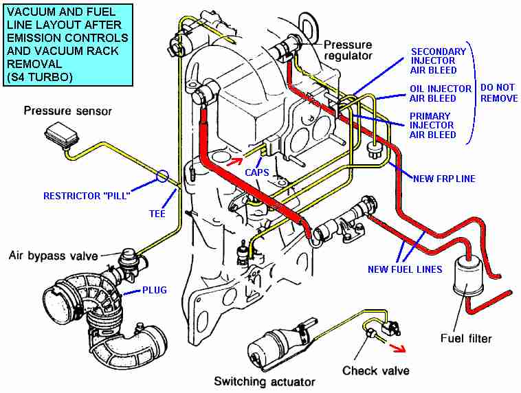
A couple notes on this. There are no s4 secondary air bleeds (no nipples by the secondary injectors on the LIM), that is only on the s5 and is thus a misprint. The switching actuator on the bottom is only for the s4 twin scroll system. If you are running an s5 turbo you don't need it.
This diagram is for full simplification, but you will give up the idle quality of the fast idle/thermowax system and idle speed control system (BAC valve). So you will probably have to push the gas pedal down a little bit to get it started up quickly and keep your foot on the gas while it warms up. You will also have to adjust the idle using the stop screw under the TMIC.
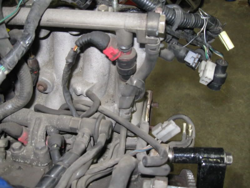
Remove all the emissions solenoids under the UIM, they have different color plugs. One more thing. In this pic, the pressure sensor and the blowoff valve are tee'd together. If you run your blowoff valve to the very bottom nipple on the front of the UIM (it is capped off in the diagram), you will find that is a better vacuum source and may cure compressor surge issues. The pressure sensor needs a restrictor pill installed. I believe it is the "vacuum hose orifice" near the bottom here: http://www.mazdatrix.com/pictures/c-intake/orifice.jpg
when you are capping off vacuum lines, use the ones here:
http://www.mcmaster.com/ctlg/DisplCt...54344087987953
scroll down to "EPDM rubber caps." These are not very expensive and will last much longer than the shitty autozone ones which crack from the heat. Most of the small ones are 5/32" . the caps are kind of long (you'll see what I mean when you get them), but just cut the end off so they aren't hanging off the end of the vacuum nipple.

Trending Topics
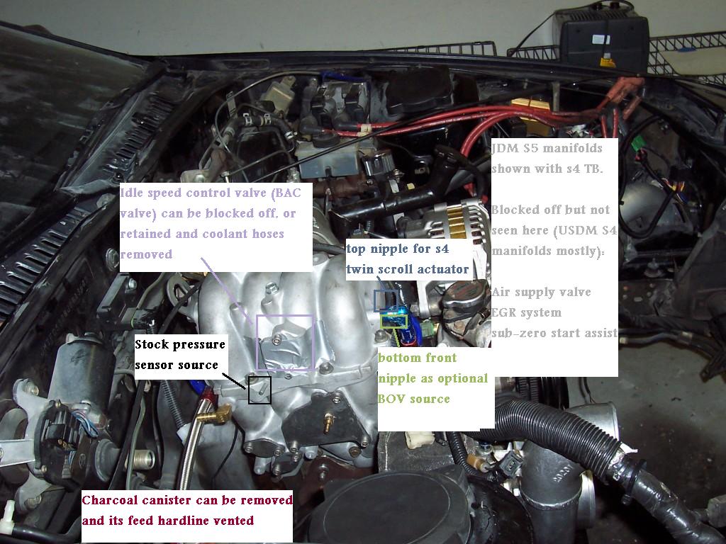
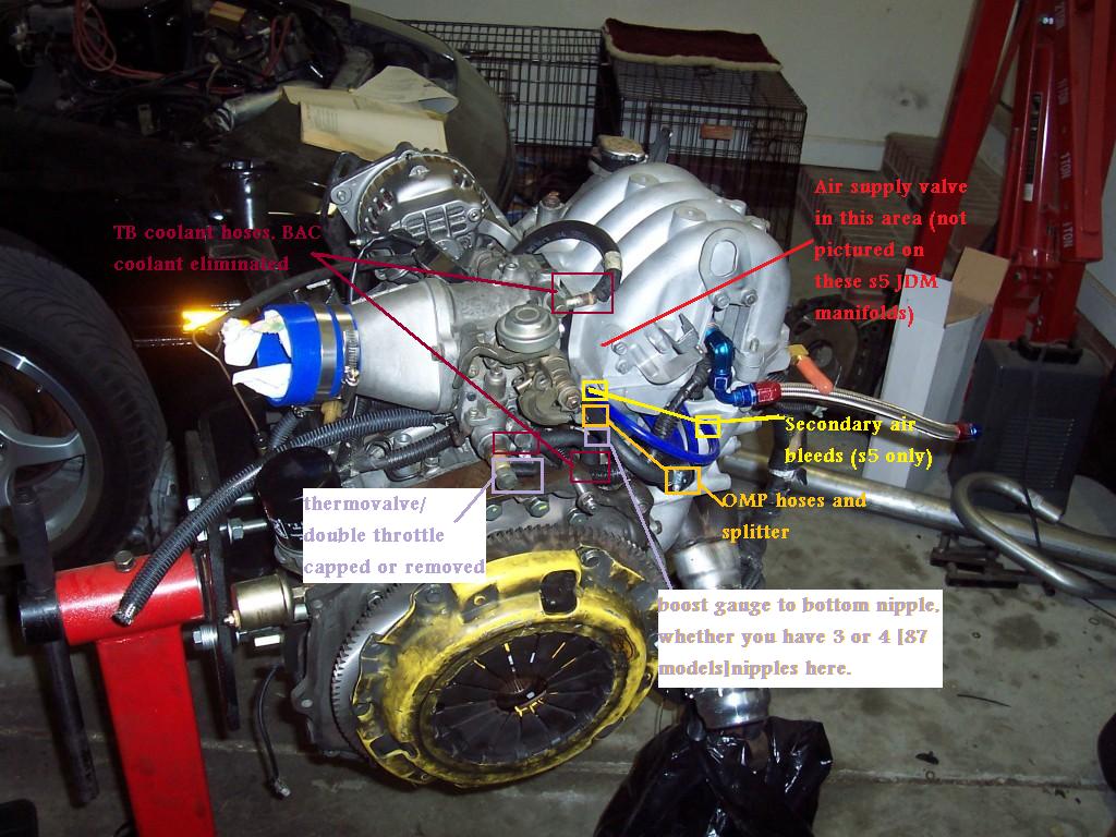
A couple notes on these pics. First of all, they're really...busy. There's a lot of colors and labels going on, but it is a vacuum routing diagram. I haven't been on stock turbo in a while, and these pics were actually taken a couple weeks ago as I was doing vacuum routing for my new motor on the stand. The motor pictured here has JDM s5 manifolds with an s4 OMP and TB. It is running a Power FC, hence the stock engine harness.
The cold idle system (thermowax and associated stuff) was retained here. The BAC valve was in the process of being reinstalled. My bias here is that after having removed the idle control systems like everybody else, I got really sick of the car stalling more easily and running like crap every time I started it in the morning. So I put them back on in simplified form. You can keep them if you want to, it's up to you. I have shown here how to route the coolant hose for the thermowax system while removing all the other coolant hoses, which are in fact unnecessary. I have not removed the double throttle system completely, merely capped off its vacuum nipples.
The secondary butterflys are still there, but they are not held closed while the engine is cold. You can do what you want with that system, pull it off if you feel like it. I had no problem putting 386 to the wheels with a bone stock TB so I don't think it affects power noticeably. After I put a stock TB back on (double throttle system fully hooked up) I personally noticed zero difference in throttle response once the engine was warm, but others do not share that opinion.
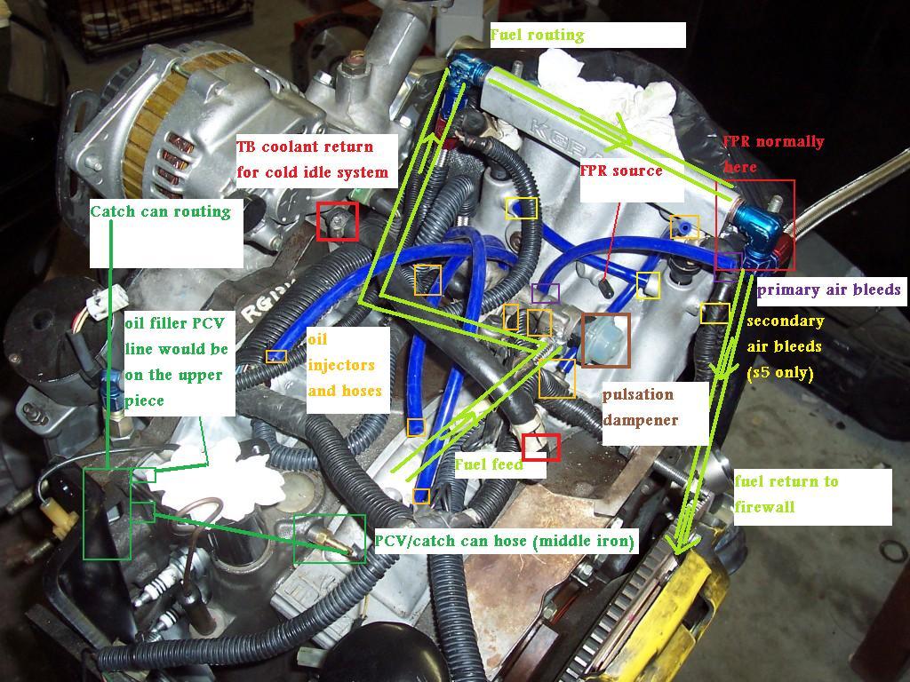
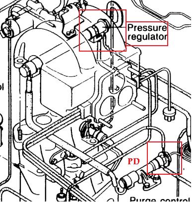
On to the pics. Note that these JDM s5 manifolds do not need blockoff plates for the air supply valve, EGR, or sub-zero start assist. The fuel routing diagram was done such that it would not block other stuff in the diagram. It goes Fuel filter --> primary rail through the pulsation dampener --> secondary rail --> exit to fuel return line, through the FPR
The cold idle system (thermowax and associated stuff) was retained here. The BAC valve was in the process of being reinstalled. My bias here is that after having removed the idle control systems like everybody else, I got really sick of the car stalling more easily and running like crap every time I started it in the morning. So I put them back on in simplified form. You can keep them if you want to, it's up to you. I have shown here how to route the coolant hose for the thermowax system while removing all the other coolant hoses, which are in fact unnecessary. I have not removed the double throttle system completely, merely capped off its vacuum nipples.
The secondary butterflys are still there, but they are not held closed while the engine is cold. You can do what you want with that system, pull it off if you feel like it. I had no problem putting 386 to the wheels with a bone stock TB so I don't think it affects power noticeably. After I put a stock TB back on (double throttle system fully hooked up) I personally noticed zero difference in throttle response once the engine was warm, but others do not share that opinion.
On to the pics. Note that these JDM s5 manifolds do not need blockoff plates for the air supply valve, EGR, or sub-zero start assist. The fuel routing diagram was done such that it would not block other stuff in the diagram. It goes Fuel filter --> primary rail through the pulsation dampener --> secondary rail --> exit to fuel return line, through the FPR

stock vacuum/fuel routing diagram, FSM page 4B-5:
you are correct. previous owner hackjob. put them back, FPR's are designed to be right before the fuel return line on every car with a return fuel system that I've ever seen.
Oh and another thing I didn't post: idle adjustment with the BAC removed. Don't pull the throttle cable. Use the stop screw for the primary butterfly, under the TMIC unfortunately.
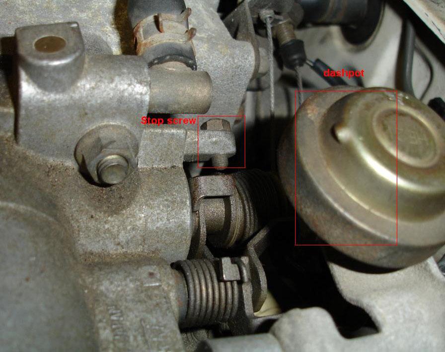
loosen/remove the nut on the end. tighten the screw down to open the throttle plates and allow more air in. Tighten the nut again to lock it in place, being mindful that tightening the nut may push the screw down a bit.
you are correct. previous owner hackjob. put them back, FPR's are designed to be right before the fuel return line on every car with a return fuel system that I've ever seen.
Oh and another thing I didn't post: idle adjustment with the BAC removed. Don't pull the throttle cable. Use the stop screw for the primary butterfly, under the TMIC unfortunately.
loosen/remove the nut on the end. tighten the screw down to open the throttle plates and allow more air in. Tighten the nut again to lock it in place, being mindful that tightening the nut may push the screw down a bit.

PIMP
Joined: Feb 2004
Posts: 1,012
Likes: 0
From: Greensboro, NC
So what happens when you have the secondary air bleed blocked off? What does it do? Also, i was having trouble finding out how the wiring harness should be positioned and where it's supposed to be routed. I had to just about force the UIM to go down because I couldn't figure out how the wiring harness should lay. I also couldn't tell which injector clips go to which injectors, but I assumed the shorter wires go to the primaries, and my **** is running alright like that, but still have vacuum leaks (sheet metal block off plates not gonna work!). thanks
The air bleeds are there to improve atomization of the fuel. They're less necessary on the secondary injectors (I think s5 are the only ones to have them) than the primary air bleed port, but I would hook them up if it's not terribly inconvenient.
Remember that the front fuel injectors are on the same branch of the harness as the green water thermosensor plug. As you noticed, the shorter ones go to the primaries. But don't cross the front and rear injectors, that will through your injector timing off. The injectors do not fire at the same time (as the GSL-SE's did) unless it is during cranking or sudden throttle movement (tip-in). The fuel and emissions section of the s4 training manual discusses injector timing.
You can kind of see how I have my harness routed above. I fed it in there by the thermostat housing. I did cut the wires for the emissions solenoid rack. You should keep the plug for the twin scroll solenoid if you have an s4 turbo and stock ECU/Rtek.
Blockoff plate kits are available from Banzai Racing and 2751 engineering.
PIMP
Joined: Feb 2004
Posts: 1,012
Likes: 0
From: Greensboro, NC
Hey arghx, thanks a million. Next time I take off the UIM i'll reconnect the secondary air bleed, atomization is important! But I was following the walk-thru on www.rotaryresurrection.com. Do you know how I would be able to find out if I have the front and rear injectors switched? The engine seems to be running pretty good with the exception of the vacuum leaks near my sheet metal block off plates.
Hey arghx, thanks a million. Next time I take off the UIM i'll reconnect the secondary air bleed, atomization is important! But I was following the walk-thru on www.rotaryresurrection.com.
Do you know how I would be able to find out if I have the front and rear injectors switched?
I understand where everything should be plugged in except for the external wastegate if your running one???

Don't really mean to resurrect this but I just wanted to say how helpful you've been arghx. been looking for all the info you put in this thread for the past few days with no luck. Thanks again for being extremely helpful 