
Need help with vacuum hoses

Originally posted by 88turborx7
5) Now the throttlebody...on the right side where according to the diagram above the primary and secondary imjector air bleeds connect and the oil injector air bleed. There are 2 small nipples and one big one. Which is which? Remember I removed the oil injectors.
5) Now the throttlebody...on the right side where according to the diagram above the primary and secondary imjector air bleeds connect and the oil injector air bleed. There are 2 small nipples and one big one. Which is which? Remember I removed the oil injectors.
Seduced by the DARK SIDE
Joined: Apr 2001
Posts: 7,323
Likes: 2
From: Orange Park FL (near Jax)
Originally posted by 88turborx7
As you can see on the 3rd line there was (or still is) some sort of checkvalve. What does each one connect to?
As you can see on the 3rd line there was (or still is) some sort of checkvalve. What does each one connect to?
I assume you have deleted that.
It's a good place to connect your mechanical boost gauge.
Seduced by the DARK SIDE
Joined: Apr 2001
Posts: 7,323
Likes: 2
From: Orange Park FL (near Jax)
The one on the right side of the UIM, just before the LIM, goes to a tee, to the waste gate, and to the pressure sensor (through an orifice pill).
Last edited by SureShot; Feb 2, 2004 at 03:54 PM.
OMG I am soo saving this thread!
I am getting my engine back from rebuilding and have to put the vac system togehter and I've never done this before!
Oh yeah the boost sensor line had that Restrictor pill note on it.
What is that? My S4 NA blocks line is too hardened to use. I'll be usuing some silicon vac hoses. Will there be any ill effects?
Hey NZ could you possibly show us the same pic but before you modifed that?
I think that would be an extremem help to understand what is removed compared to the simplistic version.
Thx.
I think that would be an extremem help to understand what is removed compared to the simplistic version.
Thx.
I'm a boost creep...
Joined: Jan 2002
Posts: 15,608
Likes: 8
From: Auckland, New Zealand
Originally posted by 88turborx7
1) On the intake manifold (S5) there is a vacuum line that runs between the 2 secondary fuel injectors and then comes out the back side(engine back). What does this connect to because on mine it is already capped off?
1) On the intake manifold (S5) there is a vacuum line that runs between the 2 secondary fuel injectors and then comes out the back side(engine back). What does this connect to because on mine it is already capped off?
5) Now the throttlebody...on the right side where according to the diagram above the primary and secondary imjector air bleeds connect and the oil injector air bleed. There are 2 small nipples and one big one. Which is which? Remember I removed the oil injectors.
6) On the back of the throttlebody there is another nipple that I don't know goes where.
Originally posted by SureShot
The one on the right side of the UIM, just before the LIM, goes to a tee, to the waste gate, and to the pressure sensor (through an orifice pill).
The one on the right side of the UIM, just before the LIM, goes to a tee, to the waste gate, and to the pressure sensor (through an orifice pill).
Originally posted by Digi7ech
Hey NZ could you possibly show us the same pic but before you modifed that?
Hey NZ could you possibly show us the same pic but before you modifed that?

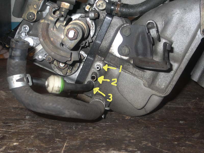
Originally posted by NZConvertible
Secondary injector air bleed. The angled one below it is for the FPR. I'm not sure what the other one is for.
Secondary injector air bleed. The angled one below it is for the FPR. I'm not sure what the other one is for.
So, in my case seeing this hose runs between the two injectors and then comes out the side (like I pointed out in the picture Motor2b) I connect that nipple to the top nipple on the Throttle body right?
I noticed maybe an error in your diagram, juts a labeling mistake perhaps. I think you mislabeled the oil injector air bleed and the thermovalve.
Just curious but speaking of the thermovalve (double throttle system), I did the TB mod, what do I connect this air bleed to now?
Sorry, forget those last 2 posts, I am starting to figure this stuff out finally. There is no error in the labeling, I just don't have the engine here with me so i am trying to do this by memory.

I'm putting my engine together tonight so just a recap.
My engine is a S5 block with S5 Manifolds and S4 TB with S4 front cover and Mech OMP.
I will not use my ACV and Airpump.
--Where does the FPR line from the Secondary rail go to? It's kind of hidden in that pic. Also the Secondary injector bleeds seem to go to the same spot.
--The front part of the UIM Vac hoses are plugged but one looks like it wasn't edited enough or it's supposed to go somewhere?
--Anything different for Vac between S4/S5 OMP's?
--The Oil injectors look a little different. Shoudl I use S4 or S5?
An answer was mentioned above but could you explain?
Also they said a Mech boost guage can be used through that one. The bottom one or one of the others?
Thx.
I'm a boost creep...
Joined: Jan 2002
Posts: 15,608
Likes: 8
From: Auckland, New Zealand
Originally posted by Digi7ech
Where does the FPR line from the Secondary rail go to? It's kind of hidden in that pic.
Where does the FPR line from the Secondary rail go to? It's kind of hidden in that pic.
Also the Secondary injector bleeds seem to go to the same spot.
The front part of the UIM Vac hoses are plugged but one looks like it wasn't edited enough or it's supposed to go somewhere?

Also they said a Mech boost guage can be used through that one. The bottom one or one of the others?
Last edited by NZConvertible; Feb 18, 2004 at 07:13 PM.
--------------------------------------------------------------------------------
The front part of the UIM Vac hoses are plugged but one looks like it wasn't edited enough or it's supposed to go somewhere?
--------------------------------------------------------------------------------
Follow the red arrows...
The front part of the UIM Vac hoses are plugged but one looks like it wasn't edited enough or it's supposed to go somewhere?
--------------------------------------------------------------------------------
Follow the red arrows...
Purge valve help
I plan on keeping the charcoal canister after all. There are two hard lines that come off the purge valve that go who knows where. I am thinking to maybe on the left side of the throttle body. I circled in red where I think that they may go. Also, in that picture, are only the two bottom lines capped off? Where does the top one go to? Thank you in advance.


If you notice I asked the same question above about the front lines.
The one with the red arrow is for the twin scroll.
Not sure about the purge valve one. I haven't gotten that far in my installation.
The one with the red arrow is for the twin scroll.
Not sure about the purge valve one. I haven't gotten that far in my installation.
I'm a boost creep...
Joined: Jan 2002
Posts: 15,608
Likes: 8
From: Auckland, New Zealand
Originally posted by 88turborx7
I plan on keeping the charcoal canister after all. There are two hard lines that come off the purge valve that go who knows where. I am thinking to maybe on the left side of the throttle body. I circled in red where I think that they may go.
I plan on keeping the charcoal canister after all. There are two hard lines that come off the purge valve that go who knows where. I am thinking to maybe on the left side of the throttle body. I circled in red where I think that they may go.
Originally posted by 88turborx7
Also, in that picture, are only the two bottom lines capped off? Where does the top one go to?[/IMG]
Also, in that picture, are only the two bottom lines capped off? Where does the top one go to?[/IMG]
Last edited by NZConvertible; Feb 26, 2004 at 02:52 PM.

Thread
Thread Starter
Forum
Replies
Last Post
ls1swap
3rd Generation Specific (1993-2002)
17
Jun 3, 2024 03:25 PM