
Latest Pics and Status Of My Turbo-NA-Bridgeport Project (Project Tina)

Thread Starter
Joined: Feb 2001
Posts: 29,798
Likes: 128
From: London, Ontario, Canada
Latest Pics and Status Of My Turbo-NA-Bridgeport Project (Project Tina)
I can't think of a snappy introduction, so let's just get down to it. Here's the latest installment in my ongoing turbo-NA-bridgeport project (Project Tina). The last thread on the subject can be found here in which the engine was installed, Microtech wired, battery box fabricated and a whole bunch of other neat stuff accomplished. This thread is a little different then most in that it primarily deals with only one task.
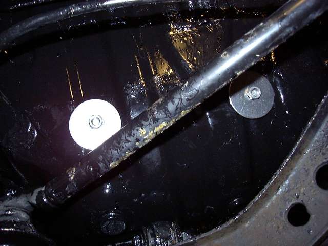
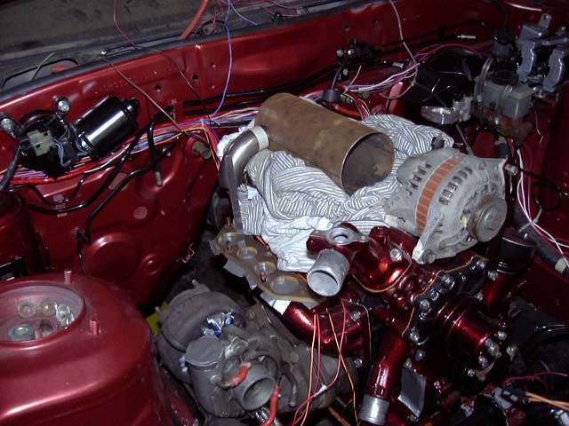
We last left off with the battery box being mounted into the passenger side storage bin. The bolts were secured on the underside of the car by using large flat washers to distribute the load. All fasteners are stainless, of course.
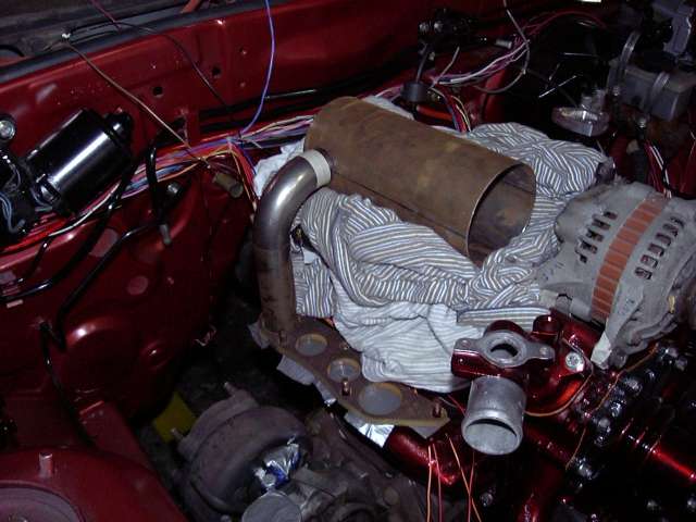
With the battery box out of the way, it was time to start a much more intricate fabrication project. The stock S4 NA intake, while being very functional in a near stock-port NA application, is not the best design for more radical configurations. Specifically, the tuning used relies on pressure waves generated by a rotor when it closes a secondary port. The runner length and width is tuned to allow this pressure wave to bounce back through the intake and force air into the opposite rotor through the open port. It works very well in a stock system, but what if you have ports that don't close such as a bridgeport? And have moved to forced induction? With a standalone? In this application simplicity and flow is more important then trying to use an intake designed for characteristics which the engine no longer possesses. Aside from that the NA intake is one very ugly piece of work, and all the emissions fittings and doodads for the stock ECU (not needed with a standalone) don't really help either.
So I had several options to "clean" it up. The TII intake is a little better but still suffers from stock ECU legacy clutter. The RE intake is a nice looking and unique piece but has the same issues as the TII intake. ITBs are great but require a new lower intake as well. For a while I had been wanting to make my own intake using a large aftermarket throttle body, plenum, straight runners and universal injector holders. Take a wild guess at what I decided to do.
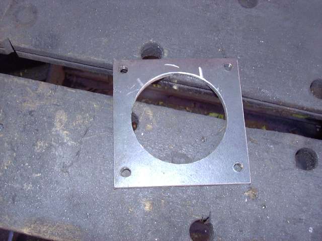
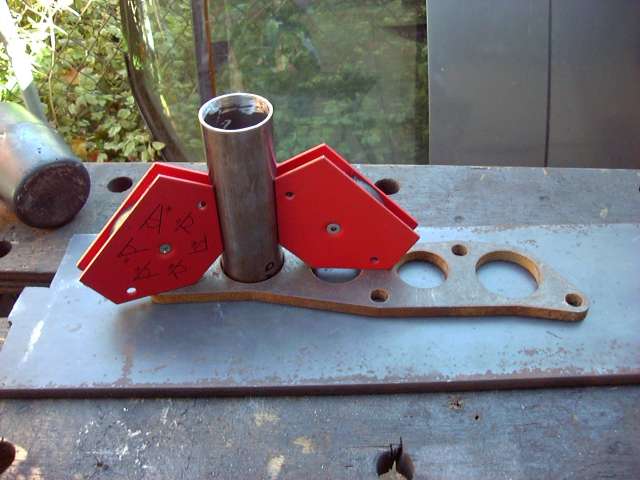
The first step starts innocently enough by fabricating a throttle body flange. 1/4" steel was used, and I began by boring a hole through it with a 3" hole saw. A sharp hole saw with the proper cutting oil and a powerful drill make this job very easy. It also helps to drill a pilot hole with a decent bit first so locate the pilot on the hole saw.
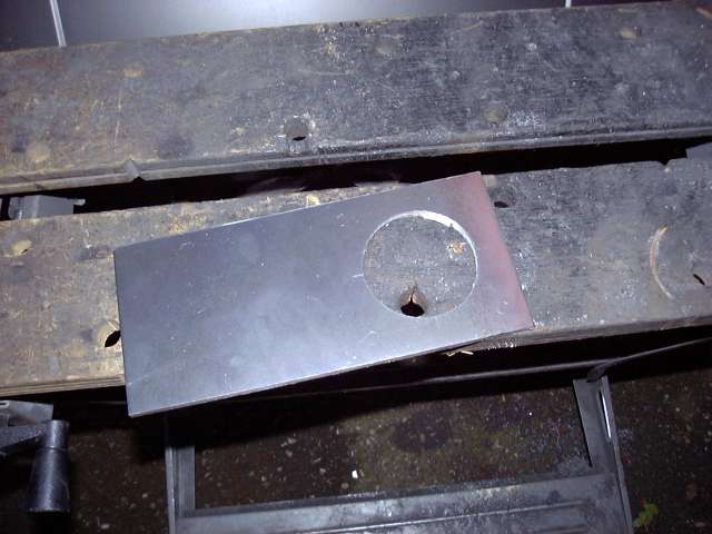
After drilling the main hole, I drilled and tapped the throttle body mounting holes. The idea was to do each step based on the probability of it screwing up. For example, drilling the big hole first so if it messes up I didn't have to redrill the 4 throttle body mounting holes. I also chose to drill the mounting holes after the big hole so that I could center the throttle body over the 3" hole first. Drilling and tapping is no big deal when you use a sharp drill bit, cutting oil, and a good set of taps. I never, ever use a tap dry unless it is in plastic, and always reverse the tap out every 1/2 turn to clear chips out of the flutes. The holes were tapped for M8x1.25, same as the stock throttle body nuts and bolts.
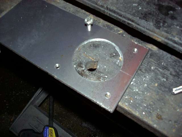
It was time to test mount the throttle body. That bad boy is an Edlebrock 75MM "Race" Mustang throttle body. What makes it "race" is that it excludes all the emissions stuff normally included in a Mustang throttle body (vacuum taps, EGR passage, etc.). It cost a little money, but the benefits are that it is band new with new seals and bearings, a full range TPS and a nifty Edlebrock sticker.
Now before anyone asks, you cannot install a throttle body like this on a stock intake. Well I guess you COULD with some fab work, but it would be a bad idea even if you are running a standalone. First it's not needed at all since the stock throttle body can flow to some crazy high horsepower numbers. Secondly, the stock ECU is NOT happy without the progressive throttle body that opens the primary ports before the secondary ports. Third, the TPS in incompatible.
Once the throttle body was fitted, I scribed a line around it so that the flange can be cut out. The flange was clamped into the work table and then each side was attacked with the angle grinder to get the rough dimensions, then the whole piece was finished off on the bench grinder.

We last left off with the battery box being mounted into the passenger side storage bin. The bolts were secured on the underside of the car by using large flat washers to distribute the load. All fasteners are stainless, of course.
With the battery box out of the way, it was time to start a much more intricate fabrication project. The stock S4 NA intake, while being very functional in a near stock-port NA application, is not the best design for more radical configurations. Specifically, the tuning used relies on pressure waves generated by a rotor when it closes a secondary port. The runner length and width is tuned to allow this pressure wave to bounce back through the intake and force air into the opposite rotor through the open port. It works very well in a stock system, but what if you have ports that don't close such as a bridgeport? And have moved to forced induction? With a standalone? In this application simplicity and flow is more important then trying to use an intake designed for characteristics which the engine no longer possesses. Aside from that the NA intake is one very ugly piece of work, and all the emissions fittings and doodads for the stock ECU (not needed with a standalone) don't really help either.
So I had several options to "clean" it up. The TII intake is a little better but still suffers from stock ECU legacy clutter. The RE intake is a nice looking and unique piece but has the same issues as the TII intake. ITBs are great but require a new lower intake as well. For a while I had been wanting to make my own intake using a large aftermarket throttle body, plenum, straight runners and universal injector holders. Take a wild guess at what I decided to do.
The first step starts innocently enough by fabricating a throttle body flange. 1/4" steel was used, and I began by boring a hole through it with a 3" hole saw. A sharp hole saw with the proper cutting oil and a powerful drill make this job very easy. It also helps to drill a pilot hole with a decent bit first so locate the pilot on the hole saw.
After drilling the main hole, I drilled and tapped the throttle body mounting holes. The idea was to do each step based on the probability of it screwing up. For example, drilling the big hole first so if it messes up I didn't have to redrill the 4 throttle body mounting holes. I also chose to drill the mounting holes after the big hole so that I could center the throttle body over the 3" hole first. Drilling and tapping is no big deal when you use a sharp drill bit, cutting oil, and a good set of taps. I never, ever use a tap dry unless it is in plastic, and always reverse the tap out every 1/2 turn to clear chips out of the flutes. The holes were tapped for M8x1.25, same as the stock throttle body nuts and bolts.
It was time to test mount the throttle body. That bad boy is an Edlebrock 75MM "Race" Mustang throttle body. What makes it "race" is that it excludes all the emissions stuff normally included in a Mustang throttle body (vacuum taps, EGR passage, etc.). It cost a little money, but the benefits are that it is band new with new seals and bearings, a full range TPS and a nifty Edlebrock sticker.
Now before anyone asks, you cannot install a throttle body like this on a stock intake. Well I guess you COULD with some fab work, but it would be a bad idea even if you are running a standalone. First it's not needed at all since the stock throttle body can flow to some crazy high horsepower numbers. Secondly, the stock ECU is NOT happy without the progressive throttle body that opens the primary ports before the secondary ports. Third, the TPS in incompatible.
Once the throttle body was fitted, I scribed a line around it so that the flange can be cut out. The flange was clamped into the work table and then each side was attacked with the angle grinder to get the rough dimensions, then the whole piece was finished off on the bench grinder.
Thread Starter
Joined: Feb 2001
Posts: 29,798
Likes: 128
From: London, Ontario, Canada
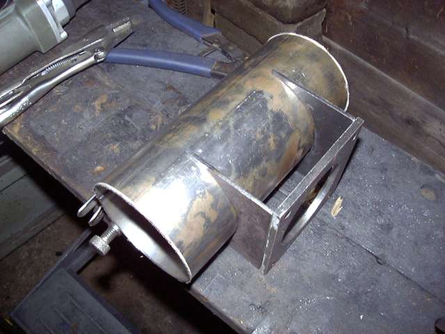
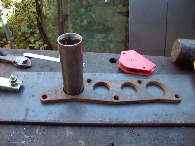
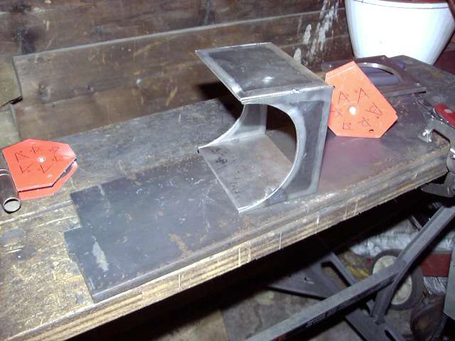
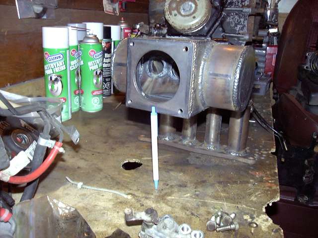
And here's the finished flange. A machinest's square was used to keep all the sides straight and the angles at perfect 90 degrees. The hole is offset slightly to one side because on the actual throttle body it is offset as well.
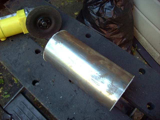
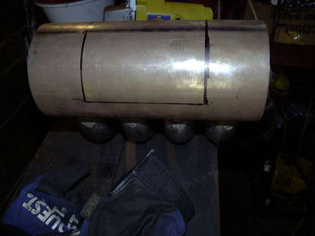
Once the throttle body flange was completed I had a general idea of how things would fit on the top of the engine. The next task then became to cut the plenum to size. It is constructed out of 4" steel tubing with a wall thickness of about 2MM. In order to cut tube straightly, the cut line must be even around the entire circumference of the tube. To achieve this a piece of paper was wrapped around the tube and the sides lined up. This formed two straight edges around the tube 8.5" apart. As luck would have it, I had already measured the plenum and determined that 8.5" was the length I wanted it. 8.5" is the approximate length of the manifold flange plus 1". It's the longest plenum that will fit without causing possible interference with the alternator and firewall. Ideally it could be a little longer to allow more area near the secondary runners to better encourage airflow.
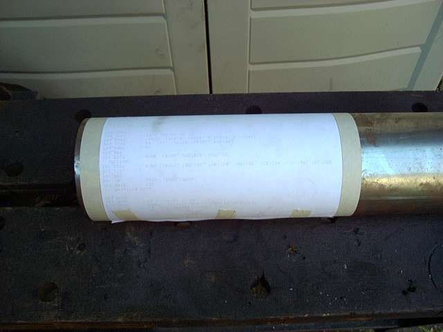
The tube was cut with a cutoff wheel on the angle grinder, then the edges were finished. I erred a little on the side of caution and cut about 1/8" long on each end just for good measure.
In order to attach the throttle body flange to the front of the plenum, two side pieces were needed. These have a flat area for the flange, and a curved area to match the plenum. They were rough cut out of a sheet of 3MM steel with the jigsaw and then the angle grinder was used to give them the curve. Each one was made individually so it would fit the plenum perfectly for easy welding.
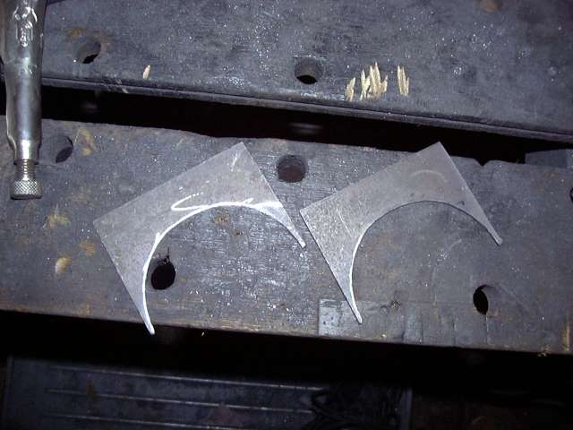
Here's a mockup of the throttle body area to give an idea of what it's supposed to look like. The top and bottom piece are just two squares of steel which fit between the two sides flush with the top of the flange. You'll see this later.
It's also interesting to note how quickly bare steel rusts in open air. When I picked up the tube originally it was shiny, but the oils and moisture from my hands had rusted it aggressively during only a few days exposure.
Once the throttle body flange was completed I had a general idea of how things would fit on the top of the engine. The next task then became to cut the plenum to size. It is constructed out of 4" steel tubing with a wall thickness of about 2MM. In order to cut tube straightly, the cut line must be even around the entire circumference of the tube. To achieve this a piece of paper was wrapped around the tube and the sides lined up. This formed two straight edges around the tube 8.5" apart. As luck would have it, I had already measured the plenum and determined that 8.5" was the length I wanted it. 8.5" is the approximate length of the manifold flange plus 1". It's the longest plenum that will fit without causing possible interference with the alternator and firewall. Ideally it could be a little longer to allow more area near the secondary runners to better encourage airflow.
The tube was cut with a cutoff wheel on the angle grinder, then the edges were finished. I erred a little on the side of caution and cut about 1/8" long on each end just for good measure.
In order to attach the throttle body flange to the front of the plenum, two side pieces were needed. These have a flat area for the flange, and a curved area to match the plenum. They were rough cut out of a sheet of 3MM steel with the jigsaw and then the angle grinder was used to give them the curve. Each one was made individually so it would fit the plenum perfectly for easy welding.
Here's a mockup of the throttle body area to give an idea of what it's supposed to look like. The top and bottom piece are just two squares of steel which fit between the two sides flush with the top of the flange. You'll see this later.
It's also interesting to note how quickly bare steel rusts in open air. When I picked up the tube originally it was shiny, but the oils and moisture from my hands had rusted it aggressively during only a few days exposure.
Thread Starter
Joined: Feb 2001
Posts: 29,798
Likes: 128
From: London, Ontario, Canada
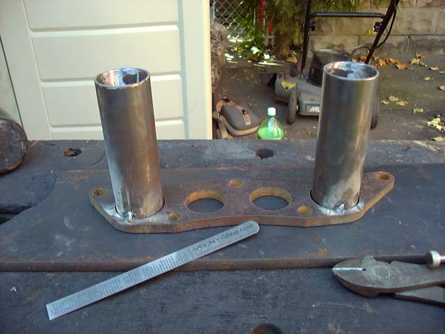
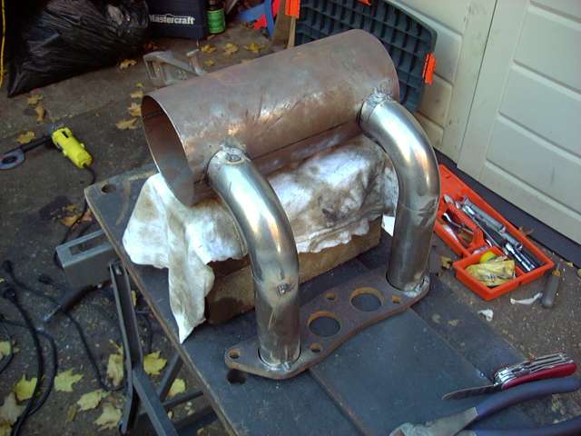
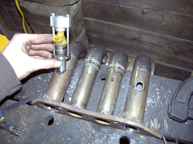
In order to attach the runners to the plenum some small adapter pieces were needed. Since end of the runner is flat it would not line up very well with the curved plenum, making it very annoying to line up and weld. The solution was to simply cut 4 birdsmouth pieces out of 1.5" tubing (same diameter as the runners). Each one was cut individually and test fitted multiple times during the process. After the birdsmouths were created, each one was cut to exactly 1.5 CM long. Having these pieces exactly the same would be critical for getting the first runners mounted straight.
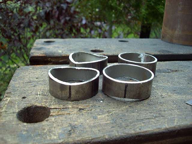
Test fitting the birdsmouths. There's still some work to be done on a few of them. I don't know why, but this picture always reminds me of bagpipes...
Now we're getting to the fun part. It was time to actually start to see what it would look like on the car. Based on research, I knew that I wanted the runners approximately 20 CM long. I was not about to put a great deal of effort into intake tuning (that is a HUGE amount of work) but I still wanted to keep the power band low enough to be useful. The 90 degree stainless weld els had an inner length of approximately 10 CM, so I needed 10CM runners.
One of the bends was attached temporarily to a birdsmouth, and then the that assembly was glued to the plenum with a glue gun. From there I stacked cloths on top of the engine and positioned the plenum, using the cloths to vary the height of the plenum. After setting it up for 10CM distance between the 90 degree weld el and the flange, I test closed the hood several times and was relieved that everything fit. It was now time to cut the runners.
More measuring.
Two 1.5" diameter runners were cut to a length of 10.5CM. The extra 5MM was to give them play, and extend into the flange for blending purposes. With a runner in place, the hood was again test closed to make sure there were no interference problems. As well, it starts to give the impression of how the finished piece would look.
Thread Starter
Joined: Feb 2001
Posts: 29,798
Likes: 128
From: London, Ontario, Canada
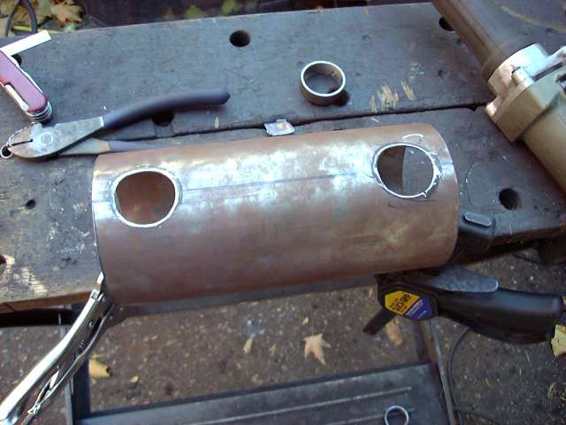
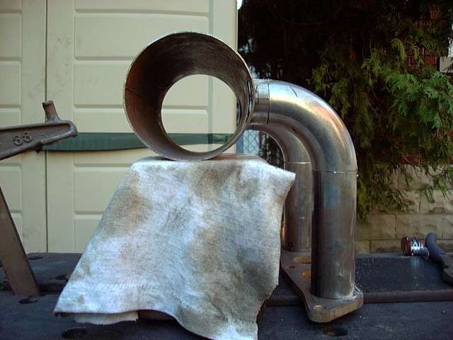
This is the point at which measuring becomes critical. The secondary runners must be perfectly straight since they are going to be used to locate the cutouts in the plenum, and thus locate the plenum itself. And since everything else comes off the plenum, it must be dead on. Welding magnets and a machinists square were used to check, check and check again the placement of the runner. It needed to be perfectly straight and extend 10.2CM from the top of the flange. The magnets were put into place and then the runners were adjusted by tapping with a hammer.
The first runner was tack welded into place, and then again checked for square. Welds always cause metal to move, so there was a certain amount of adjustment necessary to bring it back into line. This is something to pay serious attention to. Tacking must be done carefully and after each tack the assembly MUST be rechecked.
After the first runner was installed, the second followed. At this point things start to get weird, since the runners create an optical illusion and make it seem as if they are slanted. I found myself constantly rechecking only to discover that things were straight on all sides. This was a problem that would get worse as more curves were added to the assembly.
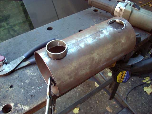
In order to locate the cutouts on the plenum, a birdsmouth was placed on top of each runner. The plenum was when placed into the birdsmouths and everything was lined up so there was equal space on each end of the plenum and the joints between the tubes were straight. Once everything lined up some minor clamping pressure kept things in place while the birdsmouth locations were traced onto the plenum with marker.
At that point each cutout was made by first using the cutoff wheel and then finishing with the die grinder. I should have just used a 1.5" hole saw as it would have taken a lot less time and truthfully, these cutouts did not need to be "perfect".
Once the holes were located the birdsmouths were tacked into place. Care had to be taken since when the tack cooled and shrunk, the birdsmouths had a tendency to "walk" in the direction of the tack. I had to anticipate how much the weld would shrink and then space the piece accordingly. The first one took several tries, but the 2nd one worked first try.
The first runner was tack welded into place, and then again checked for square. Welds always cause metal to move, so there was a certain amount of adjustment necessary to bring it back into line. This is something to pay serious attention to. Tacking must be done carefully and after each tack the assembly MUST be rechecked.
After the first runner was installed, the second followed. At this point things start to get weird, since the runners create an optical illusion and make it seem as if they are slanted. I found myself constantly rechecking only to discover that things were straight on all sides. This was a problem that would get worse as more curves were added to the assembly.
In order to locate the cutouts on the plenum, a birdsmouth was placed on top of each runner. The plenum was when placed into the birdsmouths and everything was lined up so there was equal space on each end of the plenum and the joints between the tubes were straight. Once everything lined up some minor clamping pressure kept things in place while the birdsmouth locations were traced onto the plenum with marker.
At that point each cutout was made by first using the cutoff wheel and then finishing with the die grinder. I should have just used a 1.5" hole saw as it would have taken a lot less time and truthfully, these cutouts did not need to be "perfect".
Once the holes were located the birdsmouths were tacked into place. Care had to be taken since when the tack cooled and shrunk, the birdsmouths had a tendency to "walk" in the direction of the tack. I had to anticipate how much the weld would shrink and then space the piece accordingly. The first one took several tries, but the 2nd one worked first try.
Thread Starter
Joined: Feb 2001
Posts: 29,798
Likes: 128
From: London, Ontario, Canada
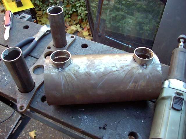
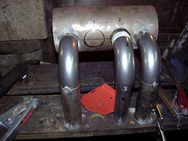
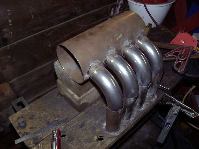
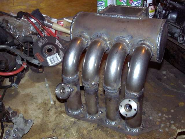
Finally the interesting stuff begins! The plenum was supported, and the lower flange and runner assembly placed below it. As it turns out, two bricks and a thin layer of cloth ended up being the exact height required. To locate the plenum, each 90 degree bend was placed such that one end was parallel to the mating surface of the birdsmouth, and the other end perfectly parallel to the top of the runner. Everything lined up without hassle the first try, and after all measurements were verified, both bends were tacked into place. Measurements were then checked again.
At this point it's starting to look like an intake. It was also obvious that the optical illusion of the multiple cures and parallel surfaces was starting to become pronounced. Every measurement I took told me that the intake was straight, but by eye it always looked warped. I think it was just a side effect of spending so much time staring at it since the feeling went away if I took a short break.
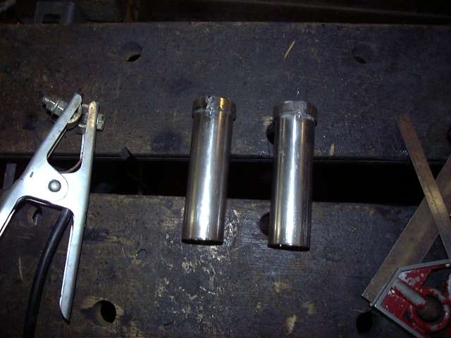
The secondary runners are 1.5", but the primary runners are 1.25". This is the closest standard measurement to stock so that the manifolds fit up properly. Also the primary runners don't need to flow as much as the secondaries due to their port size and duration as compared to the much larger secondaries. Anyway, since the 1.25" primary runners needed to meet up with 1.5" diameter weld els I had to construct two adapter rings to make things fit. The rings were made by cutting about 1CM of 1.5" tube and making a slit down the center. Careful crushing was then done with ViceGrips to shrink the diameter of the ring over the 1.25" primary runners.
A few quick tacks and the adapter rings are installed. The primary runners were cut to the same length as the secondary runners. Because of the adapter rings they ended up being a little long so they just penetrated farther into the flange.
Thread Starter
Joined: Feb 2001
Posts: 29,798
Likes: 128
From: London, Ontario, Canada
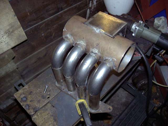
Again a birdsmouth was taped onto a 90 degree weld el and everything was set into place to get the position needed for the primary runner holes. Most of this was done by eyeball with only minimal measuring since the holes did not have to be perfect. Once all the finish welding was done, the inside of the weld are had to be ground smooth anyway so exact perfect hole placement isn't really needed for the primaries. The secondaries had to be perfect as the rest of the intake's dimensions relied on their placement.
The holes were then cut...
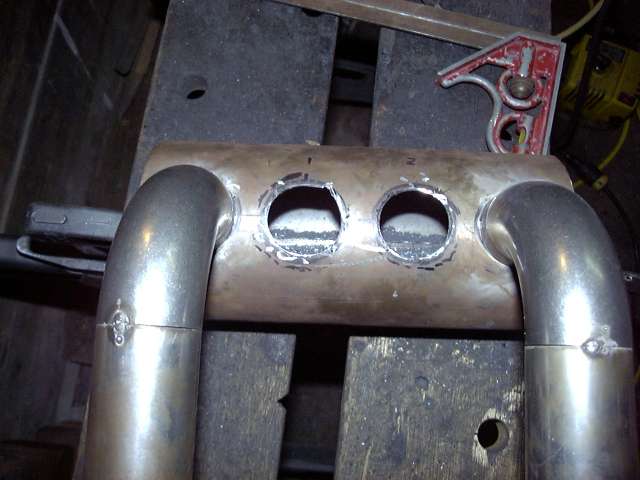
...and the birdsmouths tacked. This was an annoying process since the birdsmouths needed to be perfectly even across the entire intake. Even though they walked a little when the tack welds cooled, I was able to get them straight with a little trial and error.
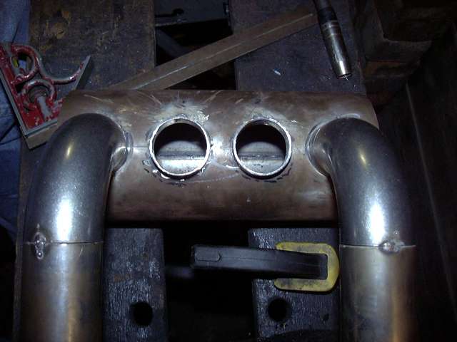
Installing the primary runners was again much more complicated then the secondaries since there was only one parallel surface to line up. The 90 degree bend went against the birdsmouth perfectly but the lower connection to the adapter ring was not as solid. The adapters fit slightly inside the 90 degree bend and centered since I had ground their tops into a taper. It was still a process of trial and error and the rightmost runner took several attempts to get right. You can also see the pronounced optical illusion in this picture caused by the intersecting lines. The plenum appears tilted towards the left based on the position of the camera, horizontal lines on the garage wall behind, and the gap between the plenum and the bricks. Measurement after measurement showed it to be less then 1MM off...I had previously chosen 1MM as my tolerance since that's about when the eye can notice something wrong. I was trying to choose my camera angles carefully to avoid this but I guess this one didn't quite work out.
With a little wiggling, some minor cursing and a few tries, the runners lined up and were tacked in place. At this point, I also placed a tack on the inside area of the secondary runners to tighten up the structure.
The holes were then cut...
...and the birdsmouths tacked. This was an annoying process since the birdsmouths needed to be perfectly even across the entire intake. Even though they walked a little when the tack welds cooled, I was able to get them straight with a little trial and error.
Installing the primary runners was again much more complicated then the secondaries since there was only one parallel surface to line up. The 90 degree bend went against the birdsmouth perfectly but the lower connection to the adapter ring was not as solid. The adapters fit slightly inside the 90 degree bend and centered since I had ground their tops into a taper. It was still a process of trial and error and the rightmost runner took several attempts to get right. You can also see the pronounced optical illusion in this picture caused by the intersecting lines. The plenum appears tilted towards the left based on the position of the camera, horizontal lines on the garage wall behind, and the gap between the plenum and the bricks. Measurement after measurement showed it to be less then 1MM off...I had previously chosen 1MM as my tolerance since that's about when the eye can notice something wrong. I was trying to choose my camera angles carefully to avoid this but I guess this one didn't quite work out.
With a little wiggling, some minor cursing and a few tries, the runners lined up and were tacked in place. At this point, I also placed a tack on the inside area of the secondary runners to tighten up the structure.
Thread Starter
Joined: Feb 2001
Posts: 29,798
Likes: 128
From: London, Ontario, Canada
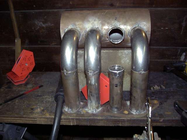
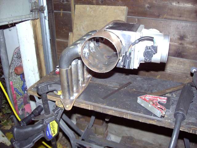
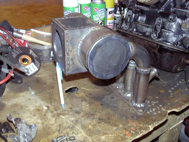
Now it's really starting to look like an intake!
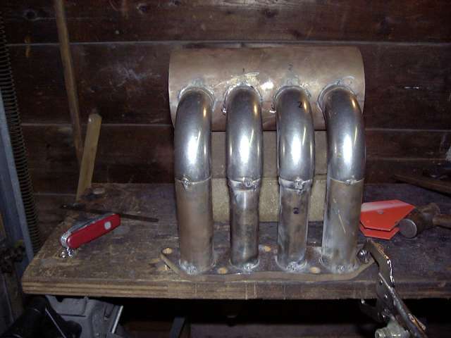
A this point I decided that I could not wait any longer for a test fit. I was quite relieved to find that yes, it still does in fact fit under the hood.
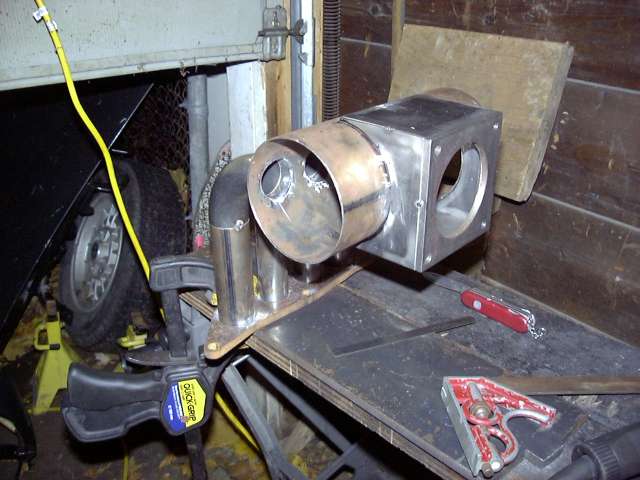
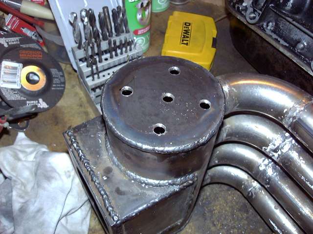
Each side of the throttle body mount was assembled separately. Magnets were used to assure perfect 90 degree angles. Again after tacking each piece needed to be straightened due to the shrinkage in the weld. A machinist square is the most important tool at this stage to keep all measurements in line. It's all in the details.
The mount halves were then assembled together using a series of inside tacks. The inside tacks brought the two halves into compression and thus prevented any warping. Final welding will take place on the outside seams.
To mark the plenum the intake was clamped via the flange to the flat table. The throttle mount was then centered and leveled by using the machinists square to assure the flange was exactly perpendicular to the table. At that point the lines were drawn. It is not vitally important that this hole be exactly perfect since there will be grinding needed later to blend the surfaces internally.
A this point I decided that I could not wait any longer for a test fit. I was quite relieved to find that yes, it still does in fact fit under the hood.
Each side of the throttle body mount was assembled separately. Magnets were used to assure perfect 90 degree angles. Again after tacking each piece needed to be straightened due to the shrinkage in the weld. A machinist square is the most important tool at this stage to keep all measurements in line. It's all in the details.
The mount halves were then assembled together using a series of inside tacks. The inside tacks brought the two halves into compression and thus prevented any warping. Final welding will take place on the outside seams.
To mark the plenum the intake was clamped via the flange to the flat table. The throttle mount was then centered and leveled by using the machinists square to assure the flange was exactly perpendicular to the table. At that point the lines were drawn. It is not vitally important that this hole be exactly perfect since there will be grinding needed later to blend the surfaces internally.
Trending Topics
Thread Starter
Joined: Feb 2001
Posts: 29,798
Likes: 128
From: London, Ontario, Canada
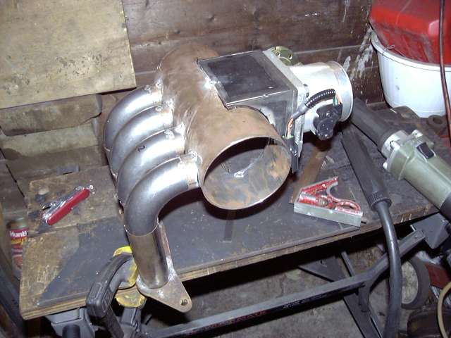
The cutout was made with a cutoff wheel and then the edges were finished with a die grinder. I was kind of worried that the huge hole I cut would cause the tube to deform and was relieved when it didn't.
Once positioned, the mount was tacked into place at the top and bottom. This took a few tries because at the tacks cooled and shrunk the mount wanted to walk in the direction of the tack.
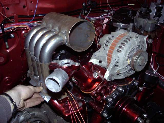
Finally I was able to test fit the throttle body. It bolted up and sat basically level so I was happy. What was even nicer is that it still fit on the car although it became obvious that the oil fill tube was totally in the way. The solution is covered later.
Once positioned, the mount was tacked into place at the top and bottom. This took a few tries because at the tacks cooled and shrunk the mount wanted to walk in the direction of the tack.
Finally I was able to test fit the throttle body. It bolted up and sat basically level so I was happy. What was even nicer is that it still fit on the car although it became obvious that the oil fill tube was totally in the way. The solution is covered later.
Thread Starter
Joined: Feb 2001
Posts: 29,798
Likes: 128
From: London, Ontario, Canada
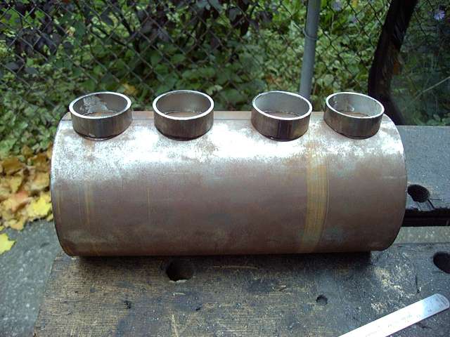
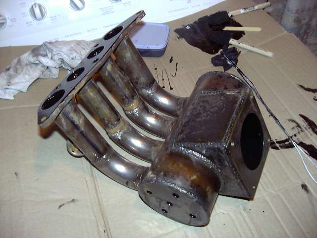
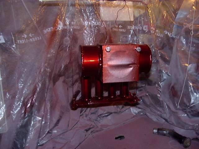
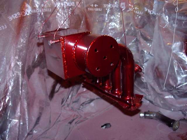
The plenum still needed to be sealed off, so two end caps were made. I don't think they turned out half bad considering I cut them out free-hand with the angle grinder after tracing the pattern using a spare section of 4" tube. The front cap was made of the same thickness steel as the rest of the intake tubing (about 1.5MM) while the rear end cap was made of thicker 3MM steel. This is to allow enough material so that the rear cap can be drilled and tapped for the intake air temp sensor and the necessary vacuum nipples.

The end caps were then tacked into place. They didn't have to be perfect since the edges would be welded and any excess material would be "absorbed" into the weld.
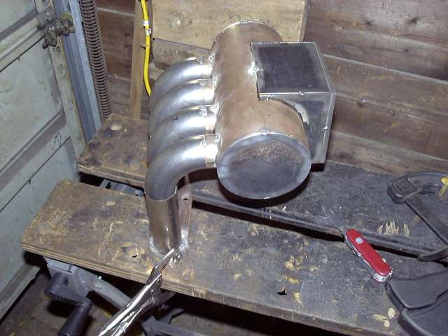
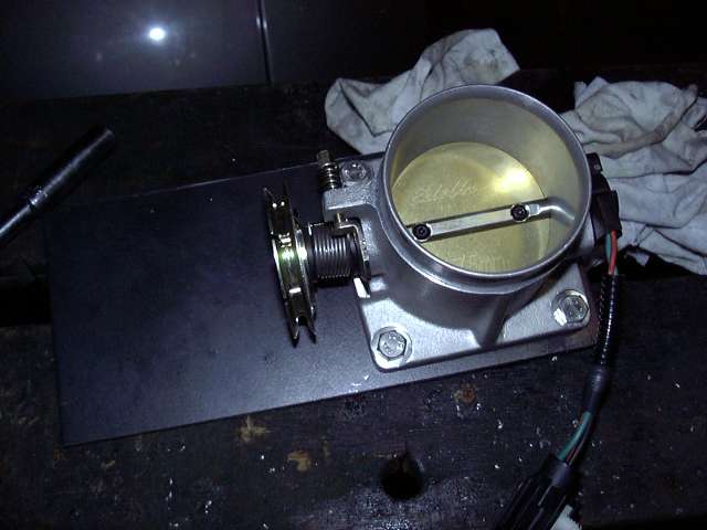
Of course on the NA, the stock upper intake manifold holds the secondary injectors so mine had to as well since I am still using the NA lower intake. I purchased some injector holders from ATP Turbo for this purpose. They make both a steel and aluminum version depending on what you intend to attach them to and each comes with a 1/4" NPT thread at the top for attachment to a fuel source. I bought steel of course. I must say I was very impressed with the quality. Installation was as simple as positioning the holder where I wanted it and marking then cutting out the appropriate sized hole. To cut the hole I initially drilled them out to about 3/8" and then used a carbide cutter on the Dremel to finish them off. The yellow injector you see in the picture is NOT the injector I will be using in the car. It's just an old Ford 220CC injector I had laying around. When the intake is bolted onto the car, I will be installing Ford 1600CC injectors which fit perfectly without modification into the ATP holders (they are designed to be as universal as possible).
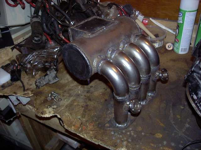
It was now time to finish-weld the intake. The original plan was to use a TIG process for neat, tiny welds but that went out the window as soon as it was realized how little space there was between the runners to fit the TIG torch. Due to this limitation it was MIG'ed together. It meant more cleanup, but also made it possible to get into the tight areas that TIG could not reach. Thanks to CP Racing for doing the welding since if I had used flux-core I probably would have had to put an additional 5 hours into cleaning it up (flux core is many things, but pretty welding process it is not). Chris welded up the intake while I was busy wiring a Megasquirt on a MKII Supra. To follow are several pictures of the totally welded intake.
The end caps were then tacked into place. They didn't have to be perfect since the edges would be welded and any excess material would be "absorbed" into the weld.
Of course on the NA, the stock upper intake manifold holds the secondary injectors so mine had to as well since I am still using the NA lower intake. I purchased some injector holders from ATP Turbo for this purpose. They make both a steel and aluminum version depending on what you intend to attach them to and each comes with a 1/4" NPT thread at the top for attachment to a fuel source. I bought steel of course. I must say I was very impressed with the quality. Installation was as simple as positioning the holder where I wanted it and marking then cutting out the appropriate sized hole. To cut the hole I initially drilled them out to about 3/8" and then used a carbide cutter on the Dremel to finish them off. The yellow injector you see in the picture is NOT the injector I will be using in the car. It's just an old Ford 220CC injector I had laying around. When the intake is bolted onto the car, I will be installing Ford 1600CC injectors which fit perfectly without modification into the ATP holders (they are designed to be as universal as possible).
It was now time to finish-weld the intake. The original plan was to use a TIG process for neat, tiny welds but that went out the window as soon as it was realized how little space there was between the runners to fit the TIG torch. Due to this limitation it was MIG'ed together. It meant more cleanup, but also made it possible to get into the tight areas that TIG could not reach. Thanks to CP Racing for doing the welding since if I had used flux-core I probably would have had to put an additional 5 hours into cleaning it up (flux core is many things, but pretty welding process it is not). Chris welded up the intake while I was busy wiring a Megasquirt on a MKII Supra.
To follow are several pictures of the totally welded intake.
Thread Starter
Joined: Feb 2001
Posts: 29,798
Likes: 128
From: London, Ontario, Canada
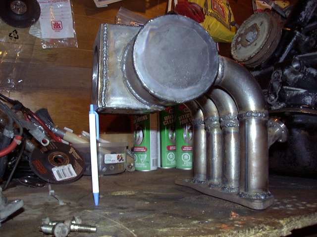
Most of the welds on the runners were ground down almost flat to make the runners appear smoother. I didn't want to make the welds invisible so I left about 0.5-1MM in tact to clearly show the joints. The idea was to make it clear that the intake was hand fabricated and not bought off the shelf.
One the grinding was done there were only a few steps left until it got painted. Most importantly the vacuum nipples and sensors had to be fitted. You can see in this picture four outer holes that were drilled and tapped for 1/8" NPT for the vacuum nipples. There are only 4 vacuum lines I am planning to use: fuel pressure regulator, BOV, purge/charcoal canister and the line into the cabin for the Microtech's MAP sensor and boost gauge. As I have mentioned in previous threads I am keeping the purge system to avoid having to empty catch-cans and to prevent the car from reeking like fuel. The hole in the middle is tapped out to M10x1 for the intake air temp sensor.
This is a very poor picture but you can just make out that the inside has been coated with POR-15. The primary concern is not corrosion, but smoothness. POR-15 dries to an almost glass smooth surface when applied properly, perfectly suitable for the inside of an intake. Think of it as a poor-man's ceramic coat. The POR-15 smoothed out all the transitions and sealed any little pockets between adjoining pieces. And the coating on the mounting flange will assure easy gasket removal in the future. You can see how the POR-15 oozed out of the vacuum and sensor holes meaning that those threads will need to be chased before final installation.
Thread Starter
Joined: Feb 2001
Posts: 29,798
Likes: 128
From: London, Ontario, Canada
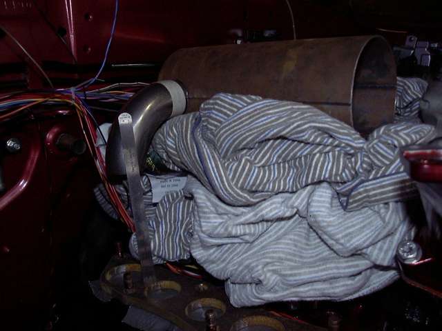
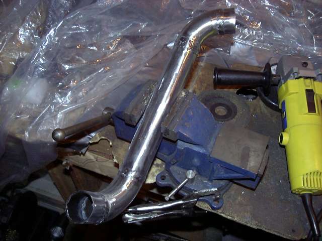
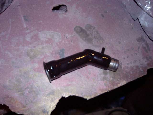
While the POR-15 dried inside the intake I turned my attention to another small fabrication project. Having a few extra weld els left over from intake making I decided to make metal replacements for the stock rubber radiator hoses. It only took a little fitting and about half an hour before the upper hose was tacked together. The next two images show that pipe compared to the stock hose.
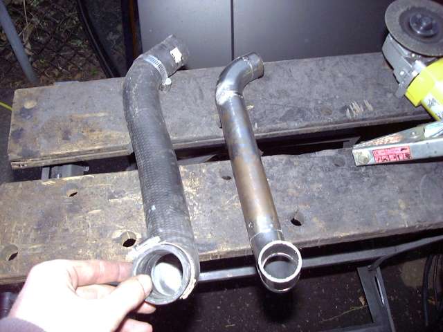
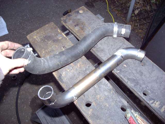
Test fitting the upper radiator pipe. It worked out perfectly. To connect it to the engine and radiator, 1.5" silicone couplers with T-bolt clamps will be used. Unlike the worm gear clamps, T-bolt clamps will not cut into the hose. The downside of course is that they are about 10x more expensive and hard to find in small diameters. I guess it's also a good time to mention that the alternator shown in these pictures is purely for mockup purposes as I'll be picking up an FD unit from silverrotor.
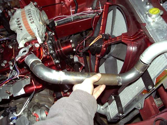
After the fit was verified the pipe was finish welded and checked for leaks.
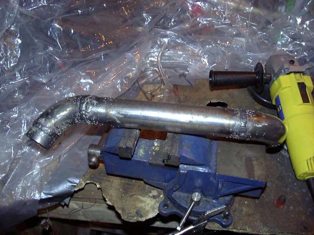
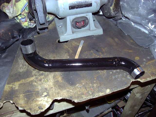
The final step before it was prepared for paint was to finish the surface with a flap disk. Again I didn't take the welds down totally to show that the pipe was hand made. I mainly just smoothed them out and removed the splatter left by the flux cored wire. Flap disks are great for this.
Test fitting the upper radiator pipe. It worked out perfectly. To connect it to the engine and radiator, 1.5" silicone couplers with T-bolt clamps will be used. Unlike the worm gear clamps, T-bolt clamps will not cut into the hose. The downside of course is that they are about 10x more expensive and hard to find in small diameters. I guess it's also a good time to mention that the alternator shown in these pictures is purely for mockup purposes as I'll be picking up an FD unit from silverrotor.
After the fit was verified the pipe was finish welded and checked for leaks.
The final step before it was prepared for paint was to finish the surface with a flap disk. Again I didn't take the welds down totally to show that the pipe was hand made. I mainly just smoothed them out and removed the splatter left by the flux cored wire. Flap disks are great for this.
Thread Starter
Joined: Feb 2001
Posts: 29,798
Likes: 128
From: London, Ontario, Canada
Now back to the intake.
Once the POR-15 dried, the outside of the intake was cleaned up with a wire wheel to remove any crud, rust, oil and welding debris left over. I decided that I would coat all the joints with JB-Weld to eliminate the possibility of pinholes. With this much welding done in tight areas and no way to pressure test the intake I was worried that there might be one or two areas that could cause trouble. I'm not a JB-Weld abuser. I hardly use the stuff so I was actually a little reluctant to post this picture since it makes the intake look like only JB-Weld was used to stick it together. Rest assured that the JB-Weld was only used as precautionary measure.
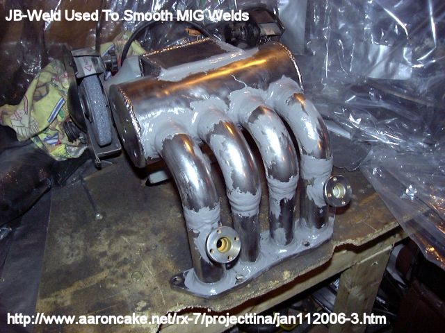
I had to let the JB-Weld cure for a few days so in the meantime I painted the upper radiator pipe with VHT's Black Caliper Enamel. I use this stuff on anything I need to paint black since it forms a very tough surface that is chemical resistant. Especially after it is baked. The inside was coated in POR-15 to prevent corrosion.
After some sanding (yeah, like 3 days of it) the JB-Weld was smooth and ready to paint.
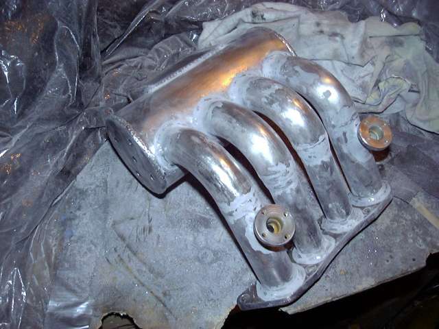
At this point it's also worth mentioning that I did have to do a good amount of grinding on the inside of the intake to smooth down any rough spots and welds. Every wonder what that long flexible attachment on the Dremel is for? It's for exactly this purpose. Getting down into the runners was actually very easy with that tool and an appropriately sized stone.
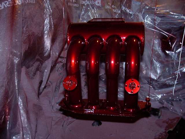
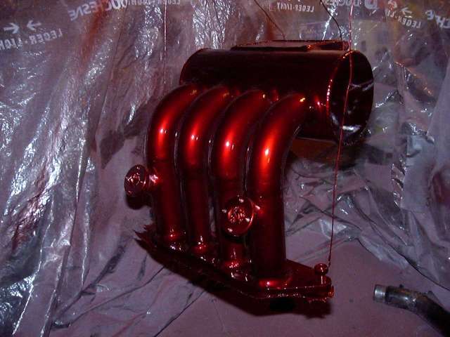
The intake was painted by first laying down 4 coats of MetalCast Base, and then 4 coats of MetalCast red. There were a few tight areas but for the most part it turned out well.
Once the POR-15 dried, the outside of the intake was cleaned up with a wire wheel to remove any crud, rust, oil and welding debris left over. I decided that I would coat all the joints with JB-Weld to eliminate the possibility of pinholes. With this much welding done in tight areas and no way to pressure test the intake I was worried that there might be one or two areas that could cause trouble. I'm not a JB-Weld abuser. I hardly use the stuff so I was actually a little reluctant to post this picture since it makes the intake look like only JB-Weld was used to stick it together. Rest assured that the JB-Weld was only used as precautionary measure.
I had to let the JB-Weld cure for a few days so in the meantime I painted the upper radiator pipe with VHT's Black Caliper Enamel. I use this stuff on anything I need to paint black since it forms a very tough surface that is chemical resistant. Especially after it is baked. The inside was coated in POR-15 to prevent corrosion.
After some sanding (yeah, like 3 days of it) the JB-Weld was smooth and ready to paint.
At this point it's also worth mentioning that I did have to do a good amount of grinding on the inside of the intake to smooth down any rough spots and welds. Every wonder what that long flexible attachment on the Dremel is for? It's for exactly this purpose. Getting down into the runners was actually very easy with that tool and an appropriately sized stone.
The intake was painted by first laying down 4 coats of MetalCast Base, and then 4 coats of MetalCast red. There were a few tight areas but for the most part it turned out well.
Thread Starter
Joined: Feb 2001
Posts: 29,798
Likes: 128
From: London, Ontario, Canada
After the paint was fully cured (about a week) the air temp sensor and vacuum nipples were installed. Because these are straight pipe threads instead of taper, sealing is important. Liberal amounts of brushable Teflon sealant was used and the fittings all tightened until they bottomed out. Notice the connection to the air temp sensor has been modified to use a WeatherPack style connector. The leads of the two pin WeatherPack connector were simply soldered to the terminals of the sensor and then adhesive filled heatshrink use to seal the whole mess. This will be much better then the stock connector that is completely exposed to the elements.
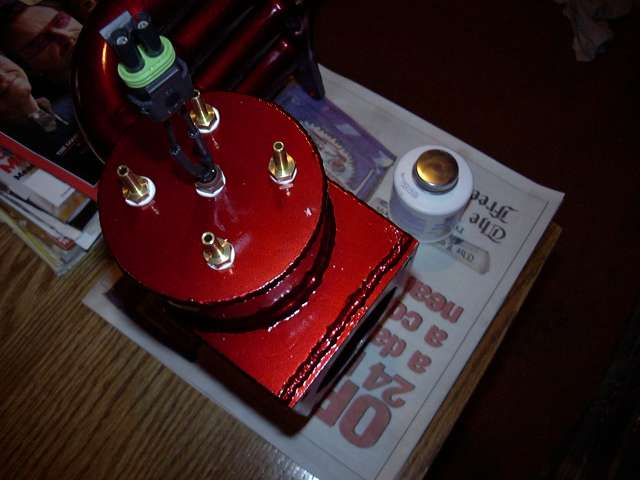
As I mentioned previously, the tall straight NA oil filler neck interferes with intercooler piping to the new intake. To rectify this I just cut the bottom off, tilted it and then welded it in place. The void was then filled by a small section of tube. It's not the prettiest thing in the world, but it will work. Yes, I could have just used the TII oil filler neck...but what's the fun in that?
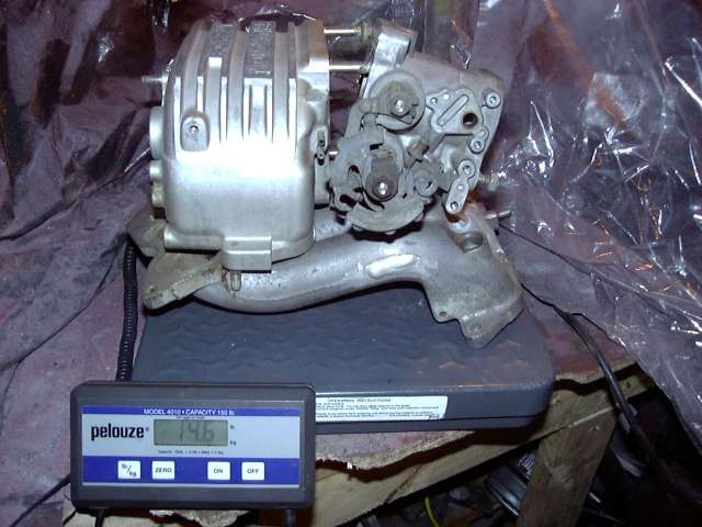
Because I know that there are many people out there about to post "Why didn't you make it out of aluminum/titanium/carbon fiber/unobtanium? Steel is so heavy! Whine!" I figured that I would compare the weights of the stock NA aluminum intake to my steel intake.
As you can see below the stock NA upper intake assembly weighs in at a hefty 14.6 LBS. And this doesn't even include the fuel rail, bolts, emissions hardware, TB spacer or mounting brackets.

Thread Starter
Joined: Feb 2001
Posts: 29,798
Likes: 128
From: London, Ontario, Canada
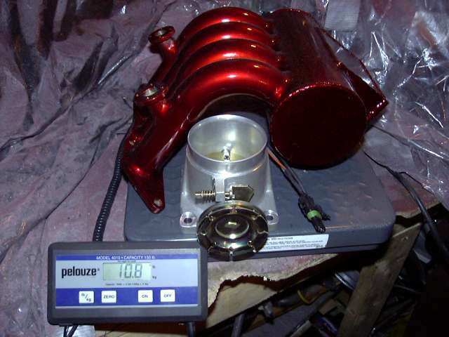
In contrast, my steel intake and throttle body weighs a feather-light 10.8 LBS. Even though the stock intake is aluminum it's castings are much thicker due to the manufacturing process and thus it gains quite a bit of weight.
And the intake manifold is officially done! Wow, that was a lot of work. It took 1.5 months of working several hours a day to get it completed and I'm pretty happy with the results. Even though I'm happy, I'm planning to make another one in the future to deal with some of the design problems I have already noticed in this first attempt.
Specifically, things I would do different are:
1. Do far more finish welding at earlier stages. For example, when positioning the secondary runners I would cut them perfectly flat on each end with a chop saw or band saw, making sure that they are the same length. I would then place the flange on a metal table so it rests flat and pass the runners through the flange so they also sit on the table. Then I would clamp the flange and runners securely in place, check my angles and completely weld them in place. The clamping should prevent them from warping and it would be far easier to weld without the other runners in the way. I would then proceed to install the bends and plenum and finish weld those in place for the same reasons.
2. Where the runners meet the inside of the plenum I would install small velocity stacks. Based on my research velocity stacks can improve flow up to 20% in plenum designs. The velocity stack would also eliminate the need for the birdsmouth cuts since they would pass through the wall of the plenum, get welded on the outside, and then the 90 degree els would attach to the protruding stack.
3. Instead of making the throttle body attachment area a box, I would use a length of 3" tubing. It would likely mean better flow, and the throttle body attachment bolt would not stick into the intake (right now they penetrate into the intake through the flange and will thus need sealant to prevent leaks). It would also be easier to fab.
4. Move injector holders down closer to the flange. It would just leave more room between the holders and the hood for a few more plumbing options.
5. Position injector holders by temporarily bolting a piece of metal bar to their faces, thus holding them perfectly parallel to each other and evenly spaced during the tacking and finish welding process.
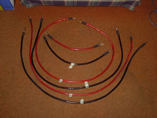
The final picture shows all the high current power cables used in the car (except those that go to the battery). They are all 4 gauge wire. Lugs were purchased at a welding store and then soldered in place. Before heatshrink was applied the end of the cable and solder joint was packed with dielectric grease and then the heatshink was shrunk around the joint. This will make a very reliable cable. Initially I purchased a bunch of lugs at a local auto parts store. Once I started working with them I saw how indaquate they would be and went for the welding store lugs. Good thing I did because not only were they WAY cheaper (70 cents a piece of the welding store lugs compared to $2.99 for 2 auto pats store lugs) but twice as thick and made of much higher quality copper.
The two short cables inside the circle are power and ground to the starter. The next red one carries power to the engine bay fuse box. The next two black and red cables carry power and ground from the electrical panel (ECU area) to the firewall passthroughs. And finally, the outer black cable is a ground cable between the firewall passthrough and drivers frame rail (stock grounding point). This grounding point is where I have also grounded my Crane HI-6 and electric fan. Another ground will likely extend from that area to the front iron of the engine for redundancy.
This thread represents the last major fab project needed to get the car running. Only a few minor things remain. These include throttle cable bracket, intercooler mounting and piping, downpipe and a few other things. All of which are very simple. For the next few months I'm going to be laying low working basically stockpiling parts and working on a 12A peripheral port side project I'm eager to get going. Next on the list is making a lower rad pipe, creating a fuel pump bracket and perhaps mounting up the intercooler.
It's likely this will be my last thread until spring at which point a lot of progress will take place very quickly.
And the intake manifold is officially done! Wow, that was a lot of work. It took 1.5 months of working several hours a day to get it completed and I'm pretty happy with the results. Even though I'm happy, I'm planning to make another one in the future to deal with some of the design problems I have already noticed in this first attempt.
Specifically, things I would do different are:
1. Do far more finish welding at earlier stages. For example, when positioning the secondary runners I would cut them perfectly flat on each end with a chop saw or band saw, making sure that they are the same length. I would then place the flange on a metal table so it rests flat and pass the runners through the flange so they also sit on the table. Then I would clamp the flange and runners securely in place, check my angles and completely weld them in place. The clamping should prevent them from warping and it would be far easier to weld without the other runners in the way. I would then proceed to install the bends and plenum and finish weld those in place for the same reasons.
2. Where the runners meet the inside of the plenum I would install small velocity stacks. Based on my research velocity stacks can improve flow up to 20% in plenum designs. The velocity stack would also eliminate the need for the birdsmouth cuts since they would pass through the wall of the plenum, get welded on the outside, and then the 90 degree els would attach to the protruding stack.
3. Instead of making the throttle body attachment area a box, I would use a length of 3" tubing. It would likely mean better flow, and the throttle body attachment bolt would not stick into the intake (right now they penetrate into the intake through the flange and will thus need sealant to prevent leaks). It would also be easier to fab.
4. Move injector holders down closer to the flange. It would just leave more room between the holders and the hood for a few more plumbing options.
5. Position injector holders by temporarily bolting a piece of metal bar to their faces, thus holding them perfectly parallel to each other and evenly spaced during the tacking and finish welding process.
The final picture shows all the high current power cables used in the car (except those that go to the battery). They are all 4 gauge wire. Lugs were purchased at a welding store and then soldered in place. Before heatshrink was applied the end of the cable and solder joint was packed with dielectric grease and then the heatshink was shrunk around the joint. This will make a very reliable cable. Initially I purchased a bunch of lugs at a local auto parts store. Once I started working with them I saw how indaquate they would be and went for the welding store lugs. Good thing I did because not only were they WAY cheaper (70 cents a piece of the welding store lugs compared to $2.99 for 2 auto pats store lugs) but twice as thick and made of much higher quality copper.
The two short cables inside the circle are power and ground to the starter. The next red one carries power to the engine bay fuse box. The next two black and red cables carry power and ground from the electrical panel (ECU area) to the firewall passthroughs. And finally, the outer black cable is a ground cable between the firewall passthrough and drivers frame rail (stock grounding point). This grounding point is where I have also grounded my Crane HI-6 and electric fan. Another ground will likely extend from that area to the front iron of the engine for redundancy.
This thread represents the last major fab project needed to get the car running. Only a few minor things remain. These include throttle cable bracket, intercooler mounting and piping, downpipe and a few other things. All of which are very simple. For the next few months I'm going to be laying low working basically stockpiling parts and working on a 12A peripheral port side project I'm eager to get going. Next on the list is making a lower rad pipe, creating a fuel pump bracket and perhaps mounting up the intercooler.
It's likely this will be my last thread until spring at which point a lot of progress will take place very quickly.
Do you think you can fab one up for IDA's?
I've been trying to learn welding as best I can but I can't jump to experienced level overnight!
My TII will need a quite similar Barrel plenum but I have IDA style ITBs
I've been trying to learn welding as best I can but I can't jump to experienced level overnight!
My TII will need a quite similar Barrel plenum but I have IDA style ITBs
i think its time for some aluminum and a tig welder. that manifold in polished aluminum would be totally awesome.
and you wouldnt have to take out a second mortgage on the house to afford all the POR-15 for rust prevention.
and you wouldnt have to take out a second mortgage on the house to afford all the POR-15 for rust prevention.


~!@#$%^&*()_+
Joined: Oct 2001
Posts: 461
Likes: 0
From: Mpls, MN
If you had used aluminum I would be givin ya high fives but since its steel....WTF were ya thinkin? I mean your that capable but you dont have a clue. How did you not realize that a steel intake is t...... condenstaion....rust....getting into..... Nevermind, its obviously not worth the time to explain.
Its so friggin awesome dude, that car is gonna effin rip. YOU ARE A ROTARY GOD.
Its so friggin awesome dude, that car is gonna effin rip. YOU ARE A ROTARY GOD.
Boost in..Apex seals out.
Joined: Nov 2003
Posts: 1,931
Likes: 0
From: Maryland, 21794
Aaron..
Everytime I read you're posts, I feel so sad. I feel like I should learn how to do all this, and that I should do all this..
On another note - how well do you think it flows over stock? Hahaha.
Think stock - Horizontal, hit a wall, down, hit a wall, go horizontal, hit a wall, go down.
Now - Horizontal, hit a wall, down.
Banned. I got OWNED!!!
Joined: Dec 2002
Posts: 4,192
Likes: 0
From: wishing i was back in FL
Originally Posted by GregW
If you had used aluminum I would be givin ya high fives but since its steel....WTF were ya thinkin? I mean your that capable but you dont have a clue. How did you not realize that a steel intake is t...... condenstaion....rust....getting into..... Nevermind, its obviously not worth the time to explain.
Its so friggin awesome dude, that car is gonna effin rip. YOU ARE A ROTARY GOD.
Its so friggin awesome dude, that car is gonna effin rip. YOU ARE A ROTARY GOD.
