
How To: Cheap and easy way to effectively mount aftermarket temp sensors


Thread Starter

Joined: Dec 2003
Posts: 6,598
Likes: 10
From: Temple, Texas (Central)
How To: Cheap and easy way to effectively mount aftermarket temp sensors
I have been trying to find a way to effectively mount an aftermarket coolant temp sensor on my car in a place that would have a constant coolant flow and wouldn't involve something major like drilling into the water pump. I also want to retain the stock sender in its stock location.
I saw somebody (I can't find the post again to give them credit) that had made his own adapter block out of aluminum and put it inline with one of the coolant hoses coming from the engine. This looked to me to be the best option for mounting the sensor. Unfortunately, I don't have access to the tools to do this and am at work when the shops that can do it are open.
This left me with one option: go to the hardware stores and auto parts stores and find something that I can make to work for my needs. After much searching and some tips that lead nowhere, I finally hit the jackpot the 3rd time I went to Home Depot.
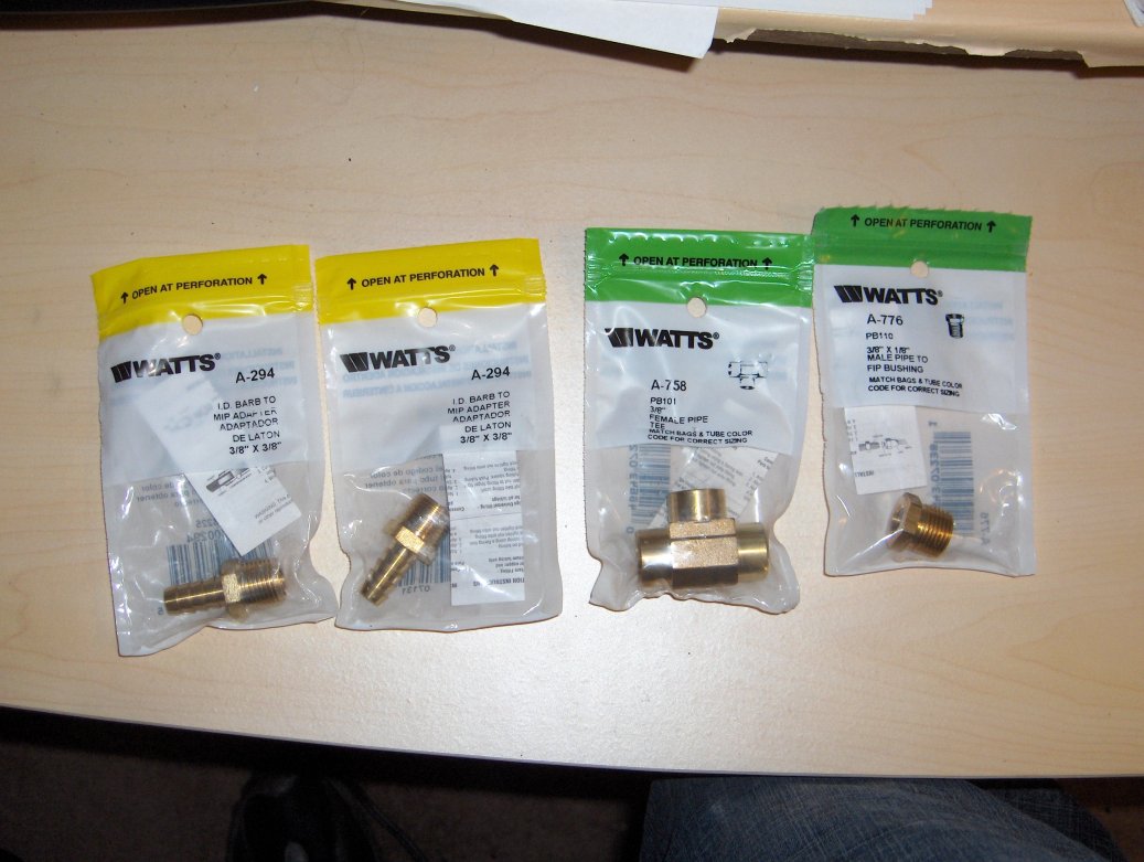
The parts are as follows:
2X Watts# A-294 - I.D. Barb to MIP Adapter � 3/8� x 3/8�
1X Watts# A-758 - 3/8� Female Pipe Tee
1X Watts# A-776 - 3/8� x 1/8� Male Pipe to FIP Bushing
All of these parts are found in the plumbing section and cost a total of $11 and change.
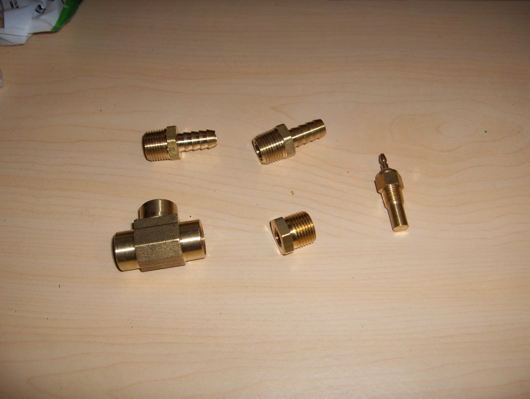
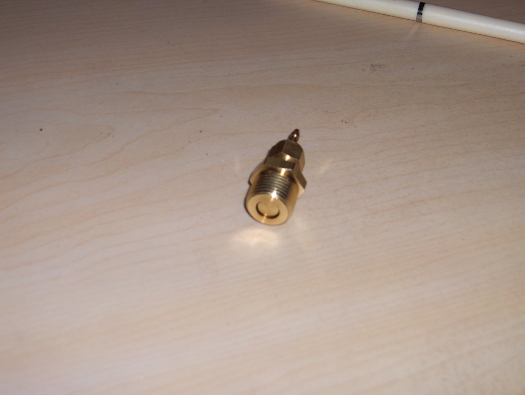
As you can see from this picture, the temp sensor doesn't fit all the way though the adapter, meaning it won't stick into the the coolant path like you want ideally.
Because of this, I put it not on the "tap" fitting, but on one of the ends so that it will have more coolant flow going over it.
I am going to put it in between the nipple on the rear iron and the BAC valve (I have bypassed the thermowax for the time being.) The rear iron nipple will connect to the barb fitting across from the sensor and the other fitting will go to the BAC (or thermowax, depending on setup.)
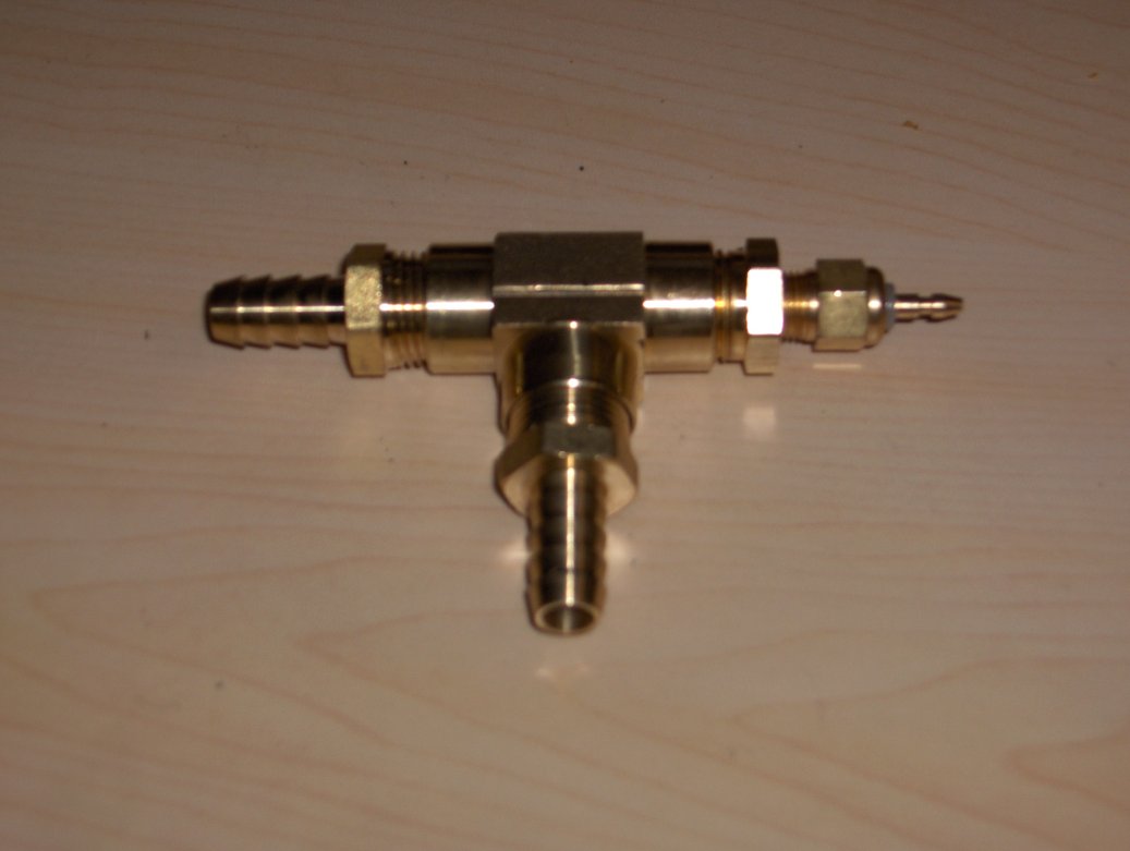
Additionally, temp sensors need a good ground. Because of this I will put a wire around the exposed threads of the temp sensor and connect it to ground. I am going to find a place to mount this assembly, most likely to the firewall with tie wraps for the moment. I will have further pictures of this once I actually install it, which will hopefully be tomorrow.
I saw somebody (I can't find the post again to give them credit) that had made his own adapter block out of aluminum and put it inline with one of the coolant hoses coming from the engine. This looked to me to be the best option for mounting the sensor. Unfortunately, I don't have access to the tools to do this and am at work when the shops that can do it are open.
This left me with one option: go to the hardware stores and auto parts stores and find something that I can make to work for my needs. After much searching and some tips that lead nowhere, I finally hit the jackpot the 3rd time I went to Home Depot.
The parts are as follows:
2X Watts# A-294 - I.D. Barb to MIP Adapter � 3/8� x 3/8�
1X Watts# A-758 - 3/8� Female Pipe Tee
1X Watts# A-776 - 3/8� x 1/8� Male Pipe to FIP Bushing
All of these parts are found in the plumbing section and cost a total of $11 and change.
As you can see from this picture, the temp sensor doesn't fit all the way though the adapter, meaning it won't stick into the the coolant path like you want ideally.
Because of this, I put it not on the "tap" fitting, but on one of the ends so that it will have more coolant flow going over it.
I am going to put it in between the nipple on the rear iron and the BAC valve (I have bypassed the thermowax for the time being.) The rear iron nipple will connect to the barb fitting across from the sensor and the other fitting will go to the BAC (or thermowax, depending on setup.)
Additionally, temp sensors need a good ground. Because of this I will put a wire around the exposed threads of the temp sensor and connect it to ground. I am going to find a place to mount this assembly, most likely to the firewall with tie wraps for the moment. I will have further pictures of this once I actually install it, which will hopefully be tomorrow.
I'm a boost creep...
Joined: Jan 2002
Posts: 15,608
Likes: 8
From: Auckland, New Zealand
You probably don't want to hear this, but that's a bad way to install a temp sensor. It must have good flow over as much of the sensing bulb as poosible. On yours only a very small part is exposed to coolant and because it's recessed it'll be in dead spot for flow. It will eventually read the right temp, but it'll be much slower to react to temp changes. If you temp suddenly increases for some reason, the gauge will show a slow temp increase and read low.
I don't recommend you continue with this, but it's up to you.
I don't recommend you continue with this, but it's up to you.
Thread Starter
Joined: Dec 2003
Posts: 6,598
Likes: 10
From: Temple, Texas (Central)
Yeah, I know its not the best way. I am going to modify it tomorrow. I will see if I can alter the threads on either the sensor or the adapter to make it sit further down, plus I plan on drilling out the adapter to allow more flow around the temp sensor.
If that won't work, them plan B is to get a 3/8" elbow and drill a hole into it then tap it out to the proper size for the temp sensor.
If that won't work, them plan B is to get a 3/8" elbow and drill a hole into it then tap it out to the proper size for the temp sensor.
Last edited by Sideways7; Apr 6, 2007 at 10:26 PM.
Thread Starter
Joined: Dec 2003
Posts: 6,598
Likes: 10
From: Temple, Texas (Central)
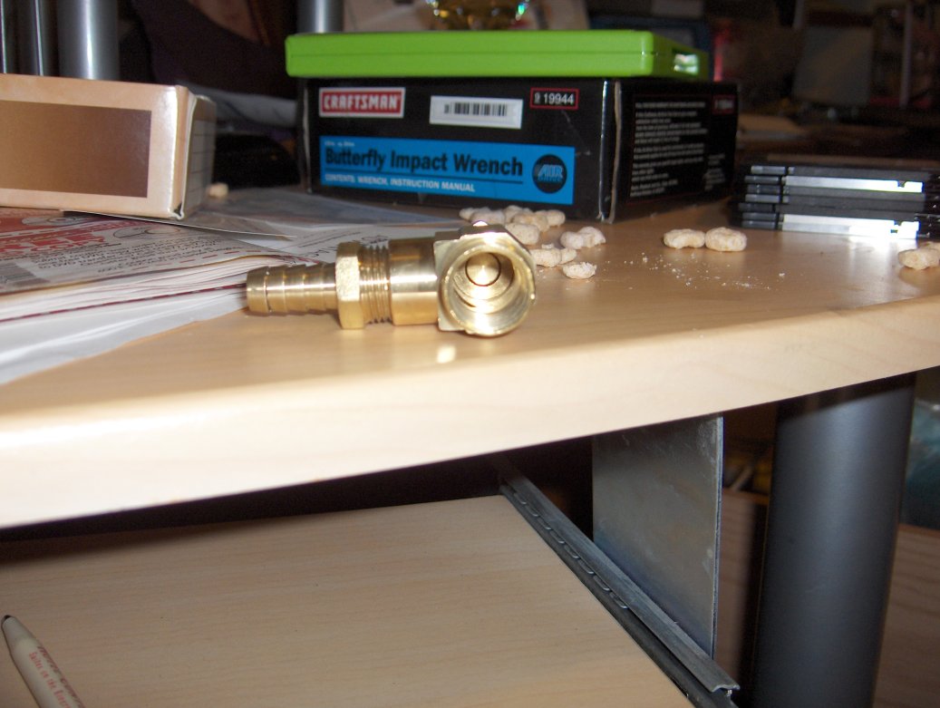
Ok, this is much better. I just took the t-fitting and drilled a 5-16" hole into the top then tapped it out with the 1/8-27 NPT tap since thats the size of my sensor.
My camera is being a bastard right now and won't upload the pics, but I will post them tomorrow.
My camera is being a bastard right now and won't upload the pics, but I will post them tomorrow.
Thread Starter
Joined: Dec 2003
Posts: 6,598
Likes: 10
From: Temple, Texas (Central)
Well, the weather has put a kink in my plans. It is currently snowing. In central Texas. In April.
Let me repeat.
It is snowing in central Texas in APRIL
WHAT THE ****. I have never in my life seen it snow like this here, let in alone in ******* April. There's like 6 inches now. Its insane.
Anyway, I'll post some pics of the stuff once I get them processed.
Let me repeat.
It is snowing in central Texas in APRIL
WHAT THE ****. I have never in my life seen it snow like this here, let in alone in ******* April. There's like 6 inches now. Its insane.
Anyway, I'll post some pics of the stuff once I get them processed.
Trending Topics
Thread Starter
Joined: Dec 2003
Posts: 6,598
Likes: 10
From: Temple, Texas (Central)
Ok, here are the pics. As you can see, there is excellent coolant flow past the sensor. I opted not to go with the elbow because it just didn't look like it would have enough room around the sensor for good flow. I just got the 3/8" square head plug in the same section to cap the open end. I used teflon tape on everything for extra sealing. Noramlly you shouldn't do this because it an prevent a good ground to the sensor, but since I am putting a wire directly on the sensor body it doesn't matter.
And finally, pics of my car with SNOW on it. I know most people could care less, but I have never seen snow in my life and it blows me away that we are getting this much, let alone in April.
And finally, pics of my car with SNOW on it. I know most people could care less, but I have never seen snow in my life and it blows me away that we are getting this much, let alone in April.
Originally Posted by Sideways7
Ok, here are the pics. As you can see, there is excellent coolant flow past the sensor.
No idea whether it will matter or not, just something to check when installed.

lol, it was sleeting in louisiana yesterday and it's still cold as all hell here today. This weather is crazy! It doesn't get cold here in louisiana past january. Crazy ****.
edit: any reason you don't want to drill and tap at the water pump housing? It's not hard and if you wanted to take your housing off to do it, it's not hard at all. Probably easier than all you went through with that fitting.
edit: any reason you don't want to drill and tap at the water pump housing? It's not hard and if you wanted to take your housing off to do it, it's not hard at all. Probably easier than all you went through with that fitting.
If he's wanting to get accurate coolant temp readings on his gauge, his best bet IMHO is at the rear iron fitting where he decided to put it already. This is more likely where the coolant is at it's hottest during engine operation. The water pump circulates coolant after the radiator has reduced temps. If he could find an area to tap a hole just before the thermostat somewhere on the housing, that would work.
We managed somehow to miss the snowfall here in OKC, but it's still cold as **** for April.
We managed somehow to miss the snowfall here in OKC, but it's still cold as **** for April.

Rotary Freak
Joined: Dec 2006
Posts: 1,791
Likes: 0
From: New Hampshire
Originally Posted by clokker
I'll grant that there is good exposure of the sensor bulb to coolant but it looks like the flow through that fitting has been severely compromised.
No idea whether it will matter or not, just something to check when installed.
No idea whether it will matter or not, just something to check when installed.
I put mine on the back of the WP housing.
Another place to install the temp sensor is on the back of the thermowax on the back of the TB. Unscrew the water thermovalve that is used to operate the 2ndary choke plates and screw the sensor into that location. Some sensors will not fit but some others will without adaptors. I am puting my Painles wiring e-fan temp sensor there. Fits perfectly without any adaptors.
Like the one that he has will fit when threaded into the adaptor. Modify the adaptor by cutting off the last few threads and possible drill out the middle a little bit without removing all the threads and you "should" have enough flow around the probe.
Thread Starter
Joined: Dec 2003
Posts: 6,598
Likes: 10
From: Temple, Texas (Central)
Originally Posted by scrip7
If he's wanting to get accurate coolant temp readings on his gauge, his best bet IMHO is at the rear iron fitting where he decided to put it already. This is more likely where the coolant is at it's hottest during engine operation. The water pump circulates coolant after the radiator has reduced temps.
Now there is actually a thermo housing in a local junkyard that is already tapped for use with a coolant sensor. Once I find a good gauge for cheap (I bought one of the cheap-o iEquus gauges for now) I'm gonna get it and put my current one after the t-stat just for the hell of it.
I'll see how it all works once I get the car running. I hope to do that tomorrow, but who the hell knows with the damn weather. Its supposed to be back in the high 70's tuesday...
As they say, if you don't like the weather in Texas, just wait a few hours.
The reason I like the water temp sensor in the water pump housing is because how fast you get your data. If you wait for the water to heat up all the way down at the rear iron than it may be to late however if you catch it getting hot right after the radiator than most of the time I would say you will be ok if you quickly shut it off. Just a thought.

GhostSS
Joined: May 2005
Posts: 281
Likes: 0
From: Phoenix, AZ
Props to ya man, thats an ingenious idea. Not saying that it'll work the best, but its good to see people fabbing stuff with what they got. I used to do stuff like that all the time, not until recently working with Elliot at Turblown have i had access to nice tools to do things the super-professional way. Again, props on your idea...
Thread Starter
Joined: Dec 2003
Posts: 6,598
Likes: 10
From: Temple, Texas (Central)
So your saying that the coolant in the water pump heats up before the coolant in the rear iron? Doesn't the coolant have to go through the rear iron before it gets back to the water pump? It just seems to me that they would be about the same temp, and if different it would be by a very small amount. I'm not saying your wrong, its not what makes sense to me.
Just for curiosity's sake, how fast does the water circulate through the engine, from the time it leaves the water pump to when it gets back? Lets say at idle and at 3k RPMs.
Just for curiosity's sake, how fast does the water circulate through the engine, from the time it leaves the water pump to when it gets back? Lets say at idle and at 3k RPMs.
Go Team Womble *)
Joined: Nov 2006
Posts: 72
Likes: 0
From: Australia
Congrates for thinking outside the square 
Here a quick pic of mine.

Still need to add the ground wire and use some jb weld to form a lip on each end.
Total cost = fuel/gas to drive to aluminium shop and ask for off cut and electricity to run the drill bit. Does help that I always have some jb weld on hand
Very Very Simple to do. I'm just mounting it in the top rad hose.
Here a quick pic of mine.
Still need to add the ground wire and use some jb weld to form a lip on each end.
Total cost = fuel/gas to drive to aluminium shop and ask for off cut and electricity to run the drill bit. Does help that I always have some jb weld on hand
Very Very Simple to do. I'm just mounting it in the top rad hose.

HAILERS
Joined: May 2001
Posts: 20,563
Likes: 27
From: FORT WORTH, TEXAS,USA
Water pump has two holes/cavitys. One is water out of the pump headed for the pan. That is the cavity on the right. That cavity has the hottest water since the water has been thru the whole engine and on its way to the radiator.
The water goes thru the radiator then back to the pump. Goes to the cavity on the left and from there into the front side housing and thru the engine. That cavity has radiator cooled air.
If you drill and install your temp sensor in the left passage, it's going to read radiator cooled water. Not the place to put a sensor.
There's a picture of the water flow in the FSM. In the COOLANT section. Has arrows showing the path of the water.
If you had a RTEK2.0, you could read the temp on a Palm. The RTEK uses the water thermo sensor for the information. If the water thermo sensor is good enough for the ECU, it's good enough to read water temps.
@HAILERS...
I see exactly what you are talking about but in the grand scheme of things does it really matter?
My understanding is that the stock gauge's shortcoming is that it's more of a three position sensor ("COLD", "NORMAL" and "YOU'RE FUCKED") and by the time it reads over NORMAL it's basically too late.
A real, full sweep gauge would show gradually increasing temp no matter where it's plumbed into the system- the actual displayed temp itself not being as important as the differential from normal.
Granted, plumbing into the cold side return line might mask/muffle the change somewhat but wouldn't it still be noticeable enough to be useful?
Just wondering.
Thread Starter
Joined: Dec 2003
Posts: 6,598
Likes: 10
From: Temple, Texas (Central)
Yes, I found the diagram in the FSM. It is actually how I decided on my location for the sensor. Now since the stock temp gauge sender is located in the rear iron, I figured that that would be a good enough place for my aftermarket one. I am hoping to have everything done on Wednesday and I'll post final pics of everything then.
I attached a pic showing its general location. I just happened to have my old s4 rear iron to TB hose laying around and it worked just about perfectly.
Also, that looks pretty good Worm Burner. Just a word to the wise, soldering onto what is effectively a heat sink is a bitch. I made what I think is my worst looking soldering job ever when I attached it to the sensor. It works, though, so thats what counts.
Thread Starter
Joined: Dec 2003
Posts: 6,598
Likes: 10
From: Temple, Texas (Central)
I ended up just wrapping the wire around the head of the sensor where the connector would go and it works fine. The sensor location seems to be excellent. It reads very well and seems to react quickly. I guess this means my thing was a success!
Rotary Freak
Joined: Dec 2006
Posts: 1,791
Likes: 0
From: New Hampshire
I ended up just wrapping the wire around the head of the sensor where the connector would go and it works fine.
A real, full sweep gauge would show gradually increasing temp no matter where it's plumbed into the system- the actual displayed temp itself not being as important as the differential from normal.
Granted, plumbing into the cold side return line might mask/muffle the change somewhat but wouldn't it still be noticeable enough to be useful?
Granted, plumbing into the cold side return line might mask/muffle the change somewhat but wouldn't it still be noticeable enough to be useful?
Either way, if you know your cooling system is functioning properly, then the usuall temp reading you see on your gauge is most likly going to be the norm.
Even when the thermostat is cold, the coolant is still flowing through the engine and back into the WP housing, just not as quickly.
Thread Starter
Joined: Dec 2003
Posts: 6,598
Likes: 10
From: Temple, Texas (Central)
I was just looking back over this and realized I never said what I did in the place that used to have the adapter fitting, across from where the temp sender is located. I just got a 3/8" plug from the same section in Home Depot, in case you couldn't tell from the pics.
Also, I actually ended up finding the fitting that went on the connector for the temp sender and mounted it properly.
I am actually planning on doing a proper writeup on how to do this and putting it on the global vicinity page once I'm done. Not sure on the time frame though, as I'm pretty busy right now.
Say I have the thermowax blocked off, is there anyway I could tap into that plate and make an effective fitting? actually since It's blocked off, the coolant one is too so that'd more than likely be a no go right?
