
HKS EVC-S Install (Pictures and Basic Walk Through)


Thread Starter
Full Member
Joined: Sep 2008
Posts: 123
Likes: 1
From: Australia
HKS EVC-S Install (Pictures and Basic Walk Through)
Hi Guys,
I bought a HKS EVC-S for the FC today and went about installing it.
The install is fairly straight forward and requires about 2 to 3 hours to complete without rushing.
Here is a basic overview of what I did...
THE NEW KIT
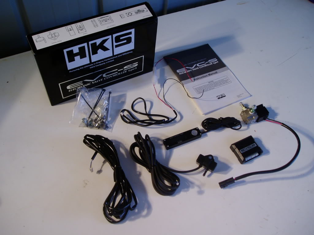
WHAT COMES IN THE BOX
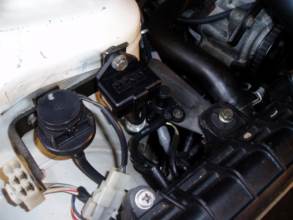
I firstly had to decide where I was going to mount the Boost Sensor. Now, as my car has a Microtech LT-10 it no longer uses thew factory Boost Sensor.
So what I did was removed the facotry boost sensor and mounted the HKS Boost Sensor in this location using trhe factory mount and nut.
BOOST SENSOR MOUNTED
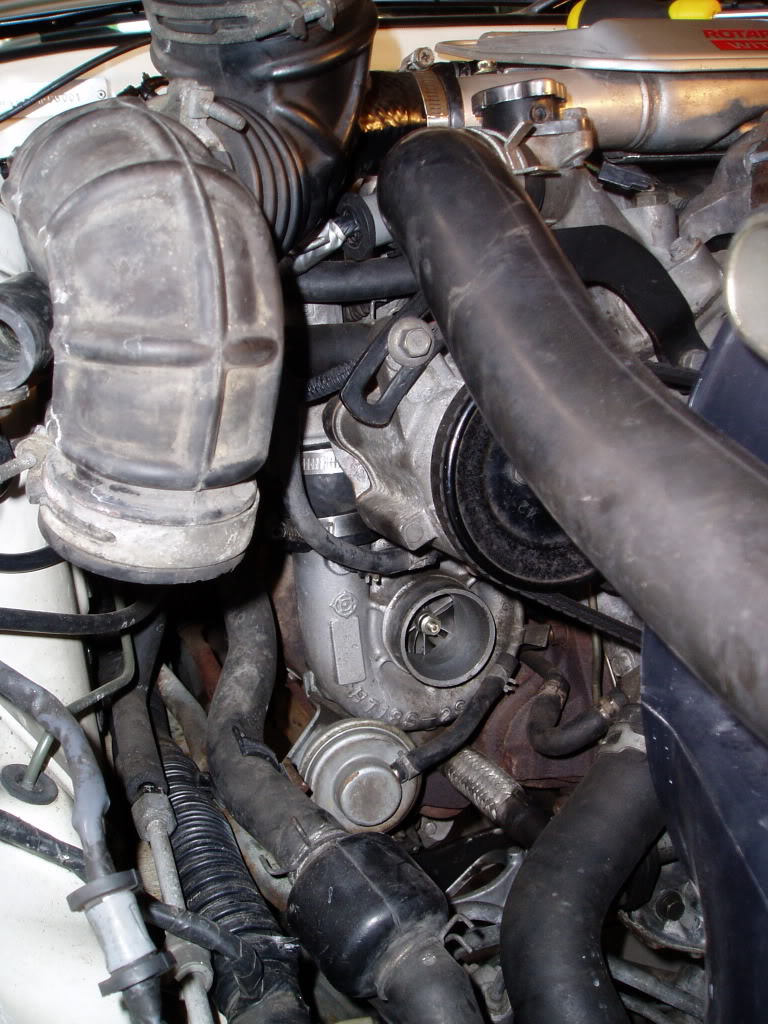
The next task was to mount the Boost Control Solenoid. I decided that BEFORE I mount this I should run the lines from the turbo and wastegate and that way I can see where the lines will end up and mount the Solenoid in a convenient place for connection to the lines.
In order to get to the Wastegate and Turbine you really need to remove the airbox and intake pipe. This frees access right up to get to the turbo.
ACCESS TO THE TURBO FOR BOOST LINE FITMENT
After fitting the lines on to the Wastegate and Turbine I then re-installed the Intake Pipe and Airbox and looked for a suitable place to mount the Solenoid.
I found the best place was on the corner of the Airbox using on of the factory Airbox nuts. This allowed space around the Solenoid and access to get the lines from the Turbine and Wastegate connected.
BOOST SOLENOID MOUNTED AND LINES CONNECTED
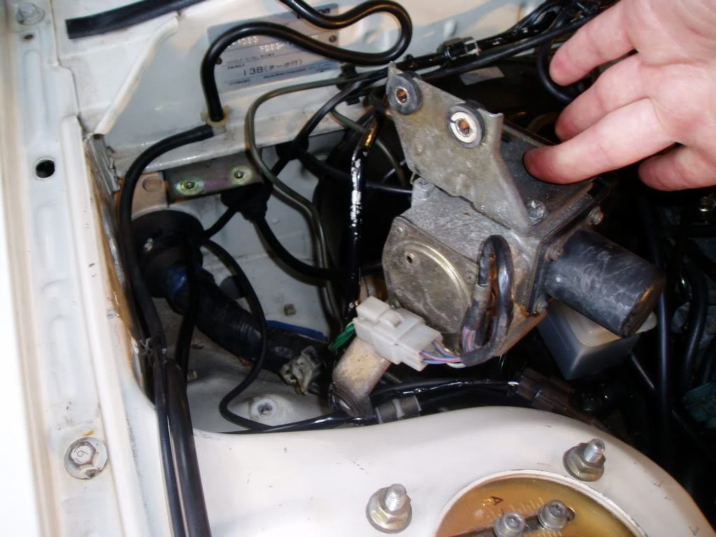
I then had to find somewhere to run the cables from both the Boost Solenoid and Boost Sensor into the cabin. I removed the Cruise Control Unit and found a spot to slip them through the firewall where the factory loom went through.
CABLES THROUGH FIREWALL UNDER CRUISE CONTROL UNIT
Now I can move into the Cabin and start to get things sorted out inside the car.
As I wanted to mount the Display Unit on my Centre Carbon Panel I had to remove the centre Dash Surround Trim and also my Carbon Fiber Panel.
REMOVING DASH TRIM AND CARBON PANEL
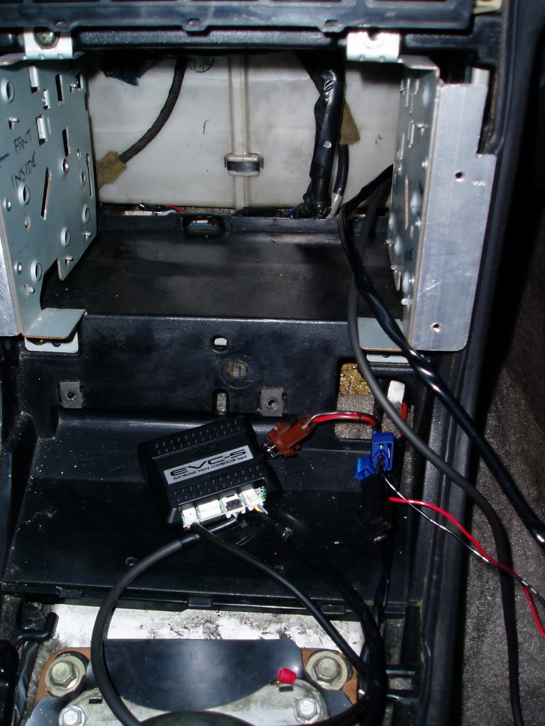
I then fed the two cables from under the dash all the way over the pedals and behind the Centre Console. This allowed me to then mount the Control Unit in the space that my stereo used to be and connect the cables to the Control Unit here.
I, at this point, also wired in the power and earth. I just spliced these into the cigarette lighter as this us triggered by ignition.
WIRING AND CONTROL UNIT STARTING TO COME TOGETHER
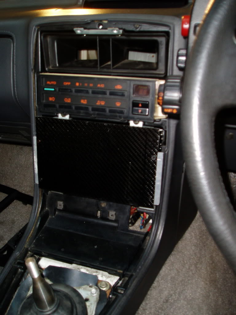
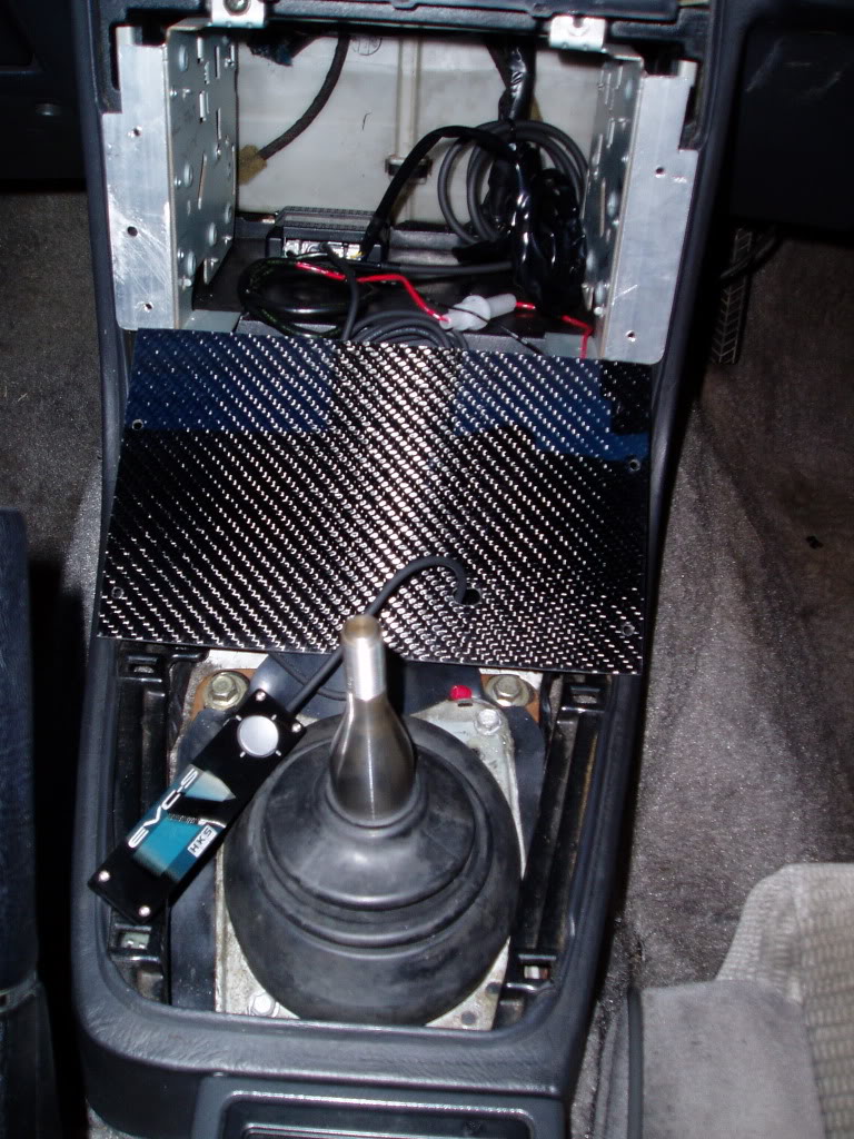
I then prepped the Carbon by drilling a hole large enough to fit the Display Unit cable through and started to fit this all in place.
CARBON PANEL AND DISPLAY UNIT COMING TOGETHER
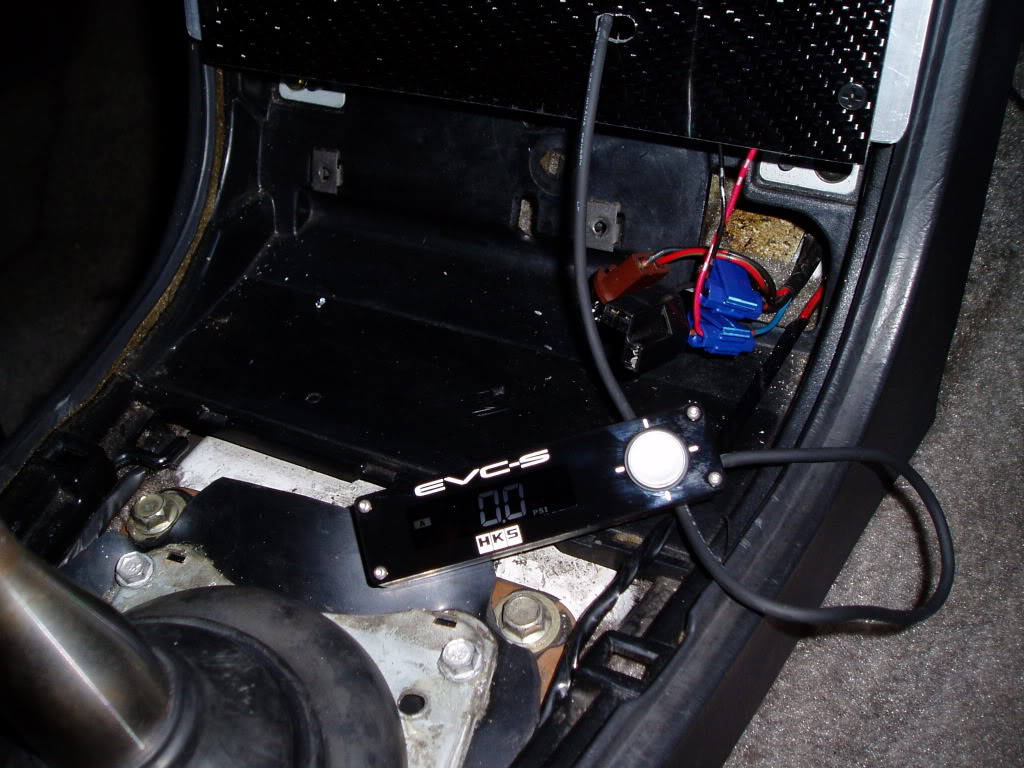
I decided to power it up and just make sure it worked so I did not end up re-assembling everything and find out the hard way.
POWERED UP FOR TEST
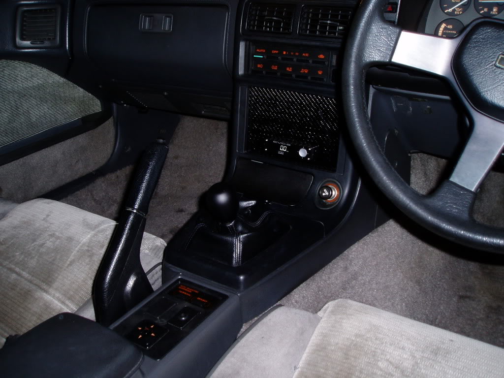
I then proceeded to re-fit everything and mounted the Display Unit in a position that will still allow me to fit two 60mm gauges above it.
ALL DONE
I bought a HKS EVC-S for the FC today and went about installing it.
The install is fairly straight forward and requires about 2 to 3 hours to complete without rushing.
Here is a basic overview of what I did...
THE NEW KIT
WHAT COMES IN THE BOX
I firstly had to decide where I was going to mount the Boost Sensor. Now, as my car has a Microtech LT-10 it no longer uses thew factory Boost Sensor.
So what I did was removed the facotry boost sensor and mounted the HKS Boost Sensor in this location using trhe factory mount and nut.
BOOST SENSOR MOUNTED
The next task was to mount the Boost Control Solenoid. I decided that BEFORE I mount this I should run the lines from the turbo and wastegate and that way I can see where the lines will end up and mount the Solenoid in a convenient place for connection to the lines.
In order to get to the Wastegate and Turbine you really need to remove the airbox and intake pipe. This frees access right up to get to the turbo.
ACCESS TO THE TURBO FOR BOOST LINE FITMENT
After fitting the lines on to the Wastegate and Turbine I then re-installed the Intake Pipe and Airbox and looked for a suitable place to mount the Solenoid.
I found the best place was on the corner of the Airbox using on of the factory Airbox nuts. This allowed space around the Solenoid and access to get the lines from the Turbine and Wastegate connected.
BOOST SOLENOID MOUNTED AND LINES CONNECTED
I then had to find somewhere to run the cables from both the Boost Solenoid and Boost Sensor into the cabin. I removed the Cruise Control Unit and found a spot to slip them through the firewall where the factory loom went through.
CABLES THROUGH FIREWALL UNDER CRUISE CONTROL UNIT
Now I can move into the Cabin and start to get things sorted out inside the car.
As I wanted to mount the Display Unit on my Centre Carbon Panel I had to remove the centre Dash Surround Trim and also my Carbon Fiber Panel.
REMOVING DASH TRIM AND CARBON PANEL
I then fed the two cables from under the dash all the way over the pedals and behind the Centre Console. This allowed me to then mount the Control Unit in the space that my stereo used to be and connect the cables to the Control Unit here.
I, at this point, also wired in the power and earth. I just spliced these into the cigarette lighter as this us triggered by ignition.
WIRING AND CONTROL UNIT STARTING TO COME TOGETHER
I then prepped the Carbon by drilling a hole large enough to fit the Display Unit cable through and started to fit this all in place.
CARBON PANEL AND DISPLAY UNIT COMING TOGETHER
I decided to power it up and just make sure it worked so I did not end up re-assembling everything and find out the hard way.
POWERED UP FOR TEST
I then proceeded to re-fit everything and mounted the Display Unit in a position that will still allow me to fit two 60mm gauges above it.
ALL DONE


HKS seems to have changed their design. A lot of the other EVC's used a stepper motor instead of a 3 port solenoid.
Good job. This installation writeup could be used for an Apex'i AVCR. The AVCR also has an external pressure sensor and solenoid. In fact, that HKS solenoid looks to be very similar to the Apex'i/Greddy solenoid made by Denso. And the connector for the solenoid is the same. It's a 2 pin Amp/Tyco Econoseal plug, same as FD boost control solenoid and similar to FC turn signal connector.
Good job. This installation writeup could be used for an Apex'i AVCR. The AVCR also has an external pressure sensor and solenoid. In fact, that HKS solenoid looks to be very similar to the Apex'i/Greddy solenoid made by Denso. And the connector for the solenoid is the same. It's a 2 pin Amp/Tyco Econoseal plug, same as FD boost control solenoid and similar to FC turn signal connector.
MECP Certified Installer
Joined: Feb 2009
Posts: 3,176
Likes: 3
From: Mesquite, TX-DFW
Unrelated...
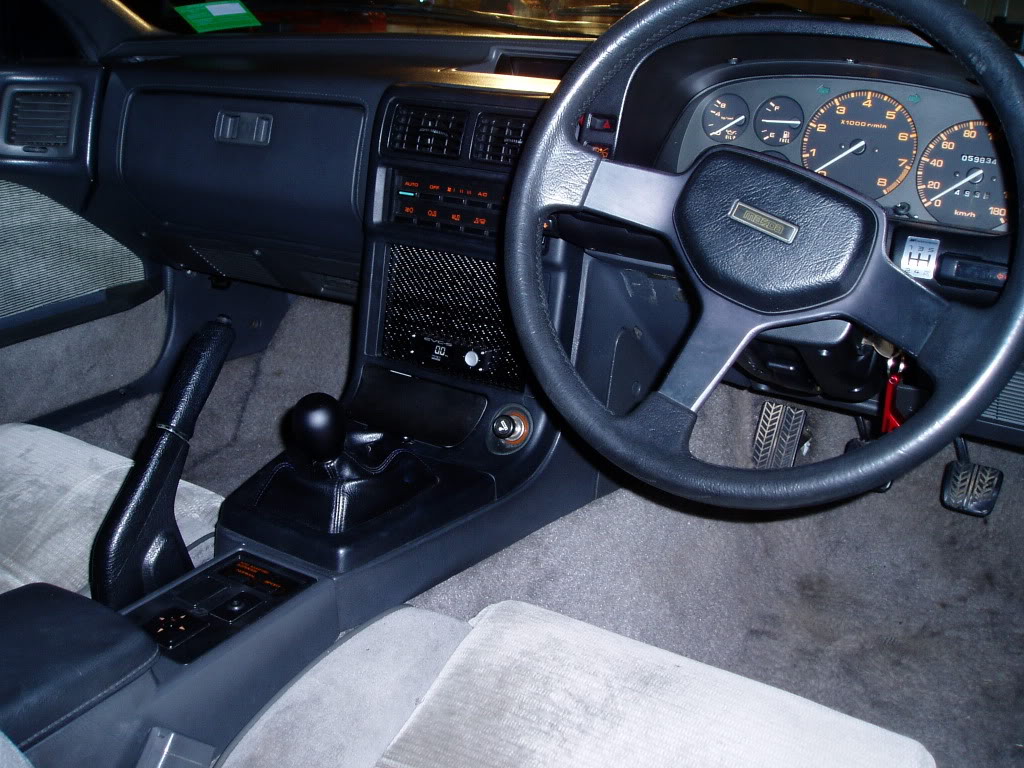
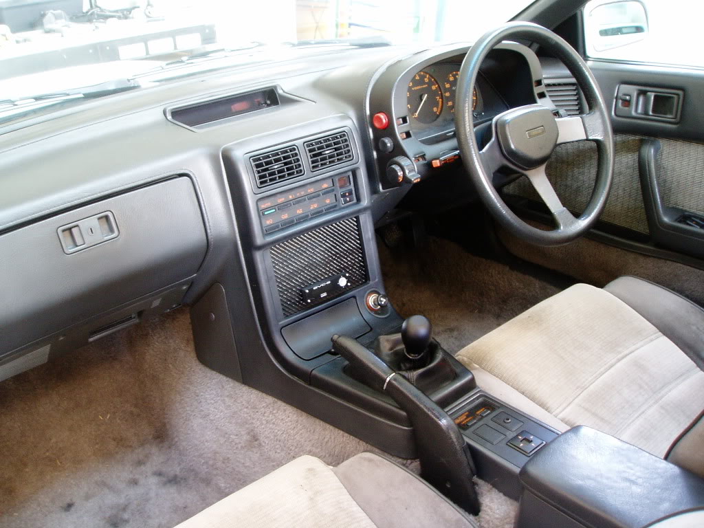
I envy your car, with the exception of RHD. I couldn't even fathom shifting with my left hand.
But I love the nice stock steering wheel in good condition, looks like the leather isn't flaking. Also, that INTACT shifter boot. I wish I had one of those.
The controller looks nice and the mounting looks good as well. Thumbs up!
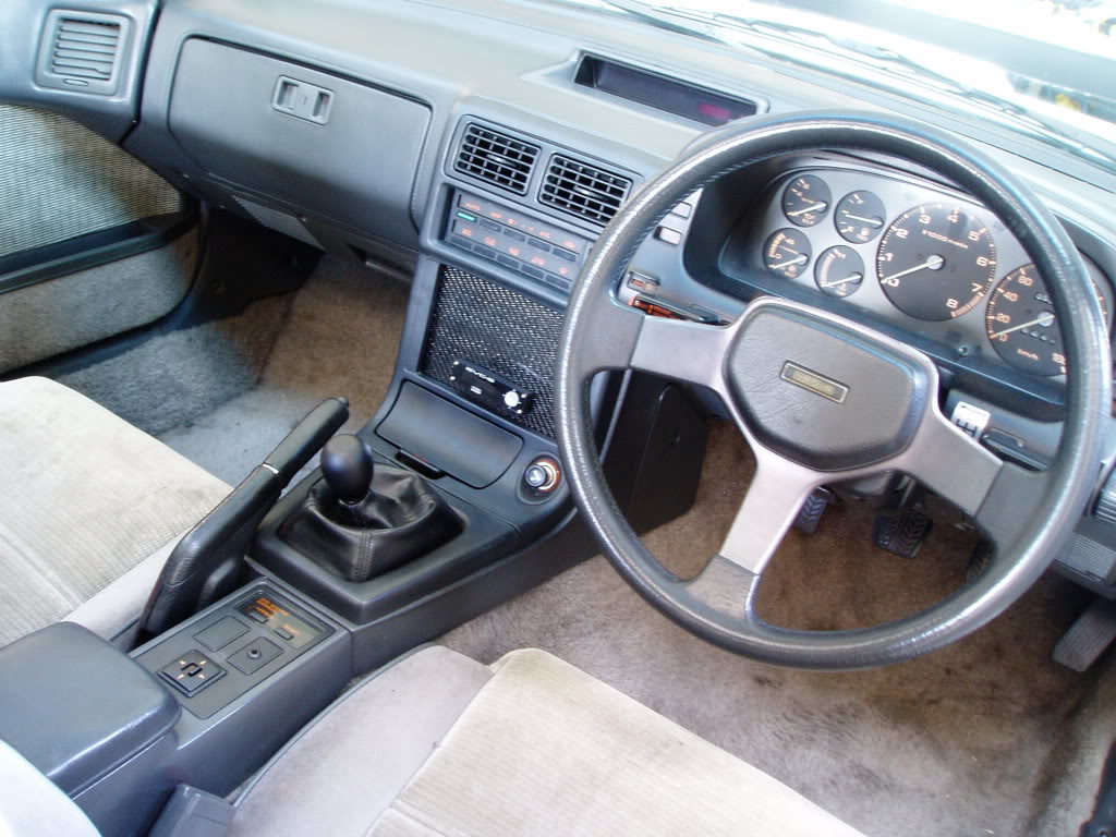
OMFG dude make another write up regarding the digital climate control install :O
I've been eyeing that longer then a boost controller, was it hard to hook up? or does it even work correctly for that matter?
I thought those digital climate control only came on the auto FC's?
I've been eyeing that longer then a boost controller, was it hard to hook up? or does it even work correctly for that matter?
I thought those digital climate control only came on the auto FC's?
Thread Starter
Full Member
Joined: Sep 2008
Posts: 123
Likes: 1
From: Australia
Thanks for the comments guys.
The digital climate control is a nice touch, thats for sure.
However, I did not custom fit it in to a manual FC....I custom fit a 5 speed transmission into an Auto FC So the Logicon was already there as a factory fit.
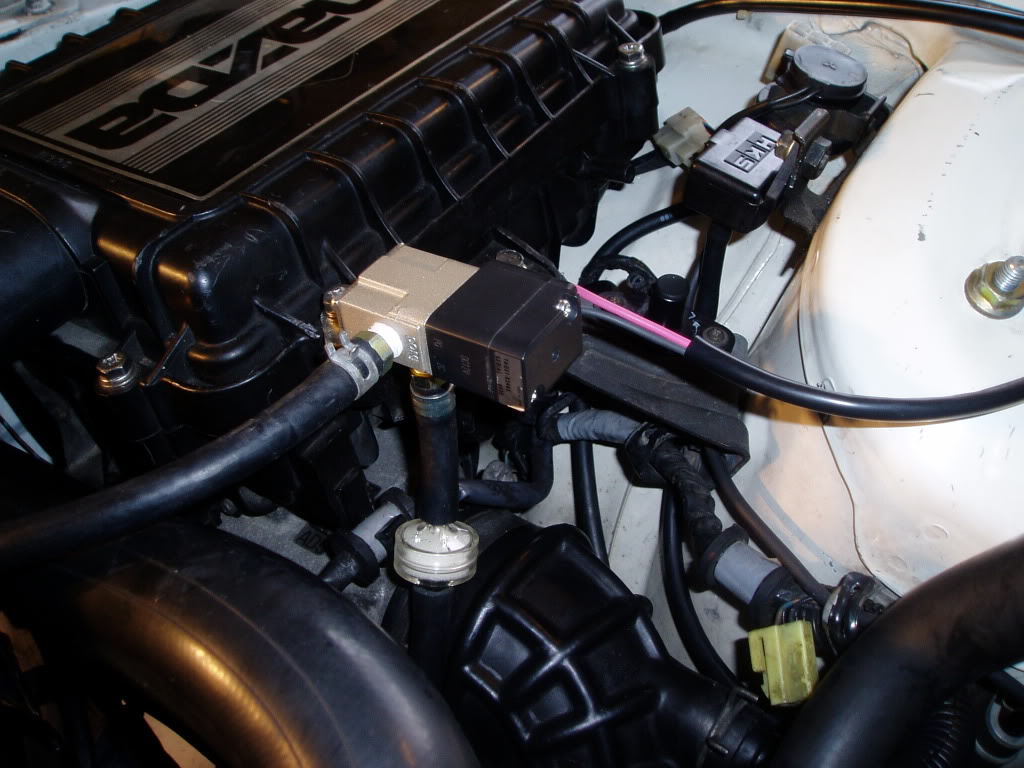
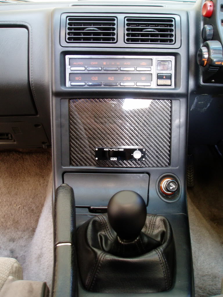
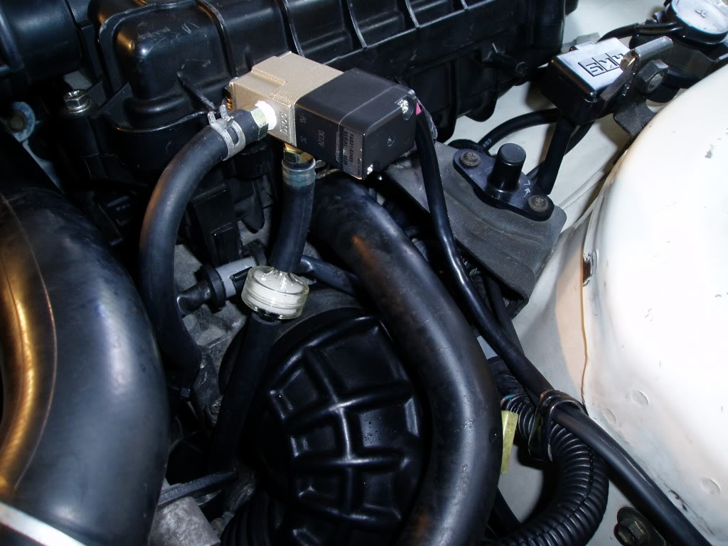
Here are some clearer photos of the Display Unit mounted, the T-Piece into the pressure line running to the Fuel Reg and the Boost Solenoid with lines running to the wastegate and turbine.
DISPLAY UNIT MOUNTED ON CARBON CENTRE DASH PANEL
T-PIECE FOR PRESSURE LINE TAPPED INTO LINE RUNNING TO FUEL REG
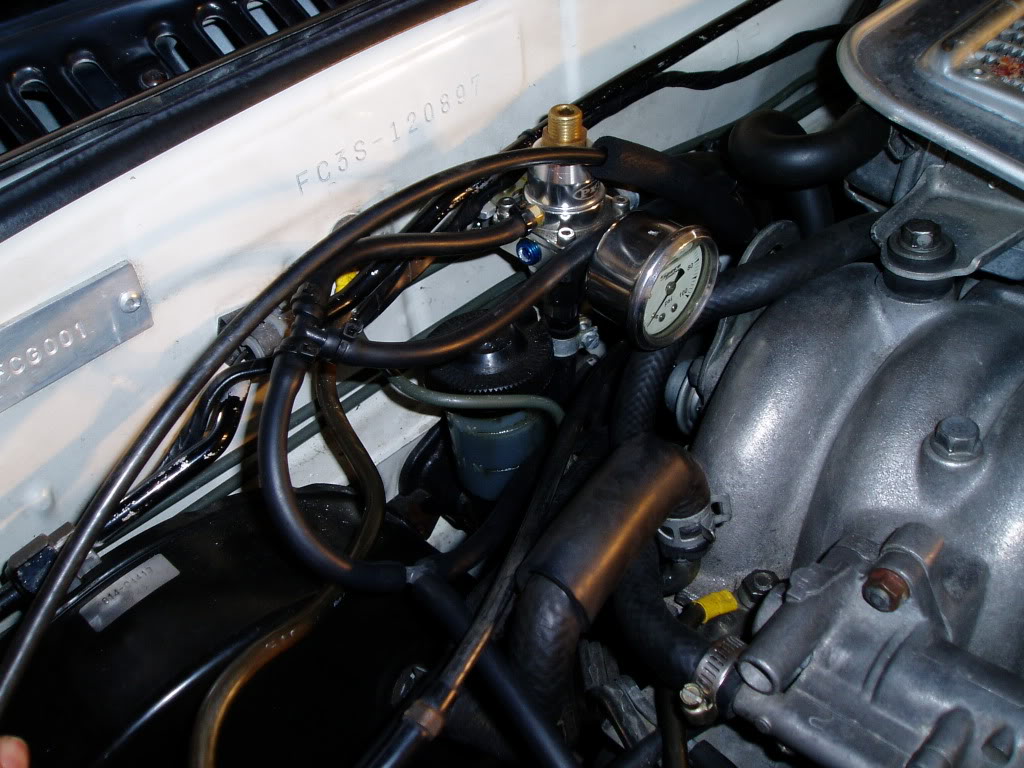
PRESSURE SENSOR WITH LINE TO FUEL REG T-PIECE
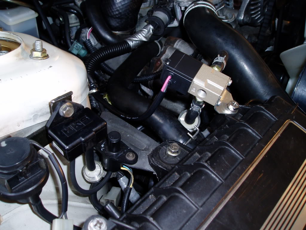
BOOST SOLENOID WITH LINES TO WASTEGATE AND TURBINE
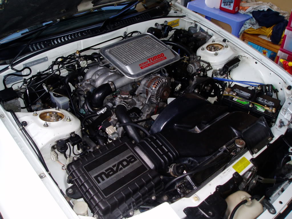
ENGINE BAY STILL LOOKS NICE AND STOCK
The digital climate control is a nice touch, thats for sure.
However, I did not custom fit it in to a manual FC....I custom fit a 5 speed transmission into an Auto FC
So the Logicon was already there as a factory fit.Here are some clearer photos of the Display Unit mounted, the T-Piece into the pressure line running to the Fuel Reg and the Boost Solenoid with lines running to the wastegate and turbine.
DISPLAY UNIT MOUNTED ON CARBON CENTRE DASH PANEL
T-PIECE FOR PRESSURE LINE TAPPED INTO LINE RUNNING TO FUEL REG
PRESSURE SENSOR WITH LINE TO FUEL REG T-PIECE
BOOST SOLENOID WITH LINES TO WASTEGATE AND TURBINE
ENGINE BAY STILL LOOKS NICE AND STOCK
Trending Topics
Full Member
Joined: Jan 2010
Posts: 90
Likes: 6
From: Greece
HOLY THREAD REVIVAL!!!
Sorry about that! I will soon be in the process of installing this EBC too...
Should I need to cap the original solenoid pipes that the S5s have or should I remove it? Will there be ny issues with the ECU if either of these happens?
And last, is the EVC-S target pressure set by the overboost or by the offset value? Opinions on the net are quite controversial.
Thanks a lot in advance!!
Marios
There is no explicit target pressure setting. "Offset" is the same as SET on a Spec II. It is a baseline duty cycle for the solenoid. "Response" is the same as GAIN on a Spec II. It is the feedback/self correcting capability of the EBC. "Overboost" is the same as "START BOOST" aka "SET GAIN" on a Spec II. It is the pressure at which the wastegate is allowed to open.
Generally speaking what you want to do is get every setting near 0 and then incrementally increase the settings. First go back and forth increasing the "Offset" and "Overboost" . Try 20% increments for "Offset" at first, and try 2-3psi increments for "oversboost." Get it set up so that you are seeing about 1 or 2 psi less than what you intend to run. Then start increasing your "response" setting. This will increase the peak boost as you spool up and reduce the amount the boost falls off. There are other methods of setting up the controller that can be made to work.
If "Response" or "Overboost" are set too high, you will have dangerous spiking or crazy boost oscillations. Use the boost warning setting as a way to cut off the solenoid in the event of overboost.
Opinions on the net are quite controversial.
Full Member
Joined: Jan 2010
Posts: 90
Likes: 6
From: Greece
Thanks a lot arghx for the rapid reply and for all the valuable information!
Hehe I'm also an electronic boost controller n00b...
What's the practical use of the overboost/Start boost in the first place? Is it intended for drag use?
Oh so setting your target pressure with a percentage (offset) sounds like it will be prone to changing according to ambient temperature and altitude conditions, just like it is now. I thought that you just dial a number in and the boost controller achieves that anytime by closed feedback.
http://www.perrinperformance.com/pages/show/113 read this. You will learn LOTS about boost control. The EVC-S uses a 3 port boost control solenoid which functions exactly like the Perrin solenoid in the article, although it looks a little different.
It operates the solenoid at basically maximum duty cycle until that pressure is reached. What that does on an internal wastegate is block pressure from pushing on the wastegate arm. Normally that keeps the wastegate completely shut. If you set overboost at 0, the wastegate will open more gradually. You won't spool as fast but you will be less likely to spike. Technically you should be able to control boost with just the "offset" setting, but it will spool slower and boost will fall off more.
You don't set target pressure. One of the only external EBCs that does that is the Apexi'i AVC-R. Honestly having a boost pressure target setting makes boost control more complicated and difficult (but also more powerful and more capable). If you look at modern OEM boost control systems built into the ECU, like on an Evo or STi, you will see a bunch of temperature and altitude compensation tables. Aftermarket controllers are too dumb for that.
and I thought signing up for Plenty of Fish meant super models would immediately start emailing me...
What's the practical use of the overboost/Start boost in the first place? Is it intended for drag use?
Oh so setting your target pressure with a percentage (offset) sounds like it will be prone to changing according to ambient temperature and altitude conditions, just like it is now.
I thought that you just dial a number in and the boost controller achieves that anytime by closed feedback.
Since you were asking about closed loop feedback that gets very close to boost targets under all conditions... here is how a real system is set up. This is from the completely stock calibration of a brand new 2011 Subaru STi.
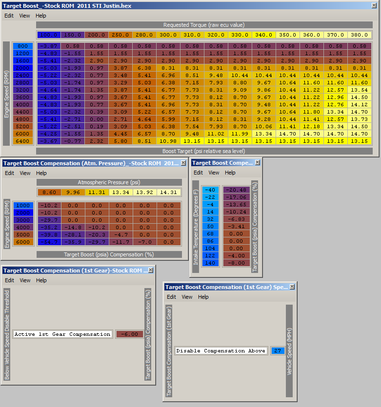
From left to right:
1) Primary target boost table. This is based on the rpm and the amount of torque requested by the driver. A higher requested torque means the gas pedal is down more. New cars have electronic throttles so there is a bunch of other stuff involved with that that I don't have here.
2) Altitude compensation table -- basically as ambient pressure decreases (higher altitude), at some rpms the boost target will decrease from its sea level values to keep from overspinning the turbo.
3) Intake temp compensation table -- reduces boost targets when intake temps (measured at the MAF sensor) are too high or too low, to prevent spiking or reduce detonation.
4) 1st gear boost compensation -- % the target boost will be reduced in at lower speeds. This is basically vehicle speed based boost control.
5) mph value above which the low speed boost target compensation will turn off.
Full Member
Joined: Jan 2010
Posts: 90
Likes: 6
From: Greece
Hahaha you rule arghx!  Happy 1st May too!
Thanks a lot for everything!
Oh what should I do with the OEM solenoid? Block the lines? Is it reachable to remove the lines right from it and block it's nipples? I guess if I unplug and remove it I will have problems with the ECU... My engine bay is stock, only the airbox is gone...
Happy 1st May too! Thanks a lot for everything!
Oh what should I do with the OEM solenoid? Block the lines? Is it reachable to remove the lines right from it and block it's nipples? I guess if I unplug and remove it I will have problems with the ECU... My engine bay is stock, only the airbox is gone...
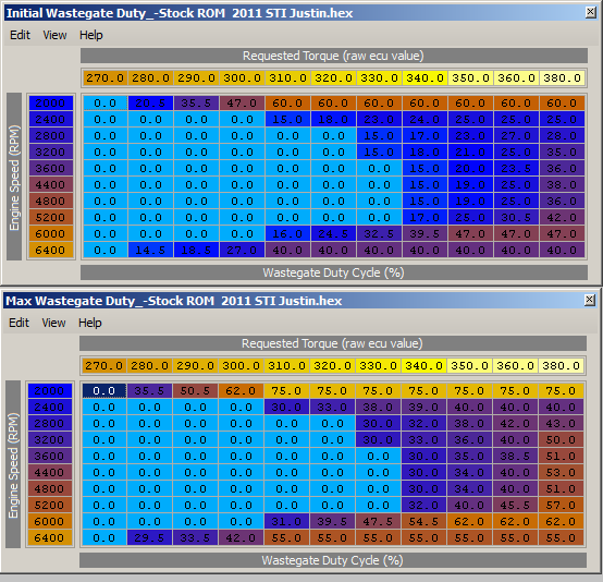
1) Main duty cycle table-- this is the solenoid duty cycle lookup table before closed loop correction is applied. it is based on rpm and requested torque (which is related to accelerator pedal position)
2) Max duty cycle table-- this sets duty cycle limits for the closed loop feedback in order to prevent overboosting.
Here are the main gain tables in the 2011 STi:
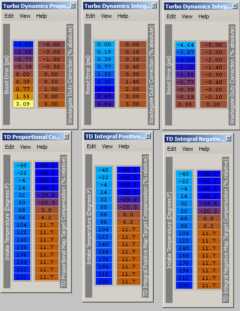
1) proportional gain table -- this type of gain is similar to what you find on an HKS EVC etc. the gain can be adjusted based on how much the boost differs from the target value
2) integral gain positive table -- this is another type of gain that you don't find in aftermarket controllers. Without getting too technical, it is more of a short term "learning" feedback that tries to smooth out oscillations.
3) integral gain positive table -- same as above but is used when boost is exceeding the target
4, 5, and 6 are intake temp compensation tables for the gain. So you can use these tables to reduce spiking in cold weather or to keep the boost from falling when it's really hot out if that's what you want to do.
So as you can see... these aftermarket controllers are very simple in comparison to what OEM engineers design on newer cars.
Last edited by arghx; May 1, 2011 at 01:45 PM. Reason: duty cycle tables
I am not sure if it will throw a code if you unplug it. You can leave it plugged in. You don't have to cap off the ports on the solenoid if you don't want to. you do need to plug the other two ports in the intake system or you will be leaking metered air.

SARX + Boost = Win
Joined: Aug 2009
Posts: 34
Likes: 0
From: San Antonio, Texas

Thread
Thread Starter
Forum
Replies
Last Post
trickster
2nd Generation Specific (1986-1992)
25
Jul 1, 2023 04:40 PM