
fd alternator problems


Thread Starter
Full Member
Joined: Aug 2007
Posts: 147
Likes: 0
From: Portland, OR
fd alternator problems
sup guys - just to start - yes i searched....
i figured this might be a good thread for us in the fc group
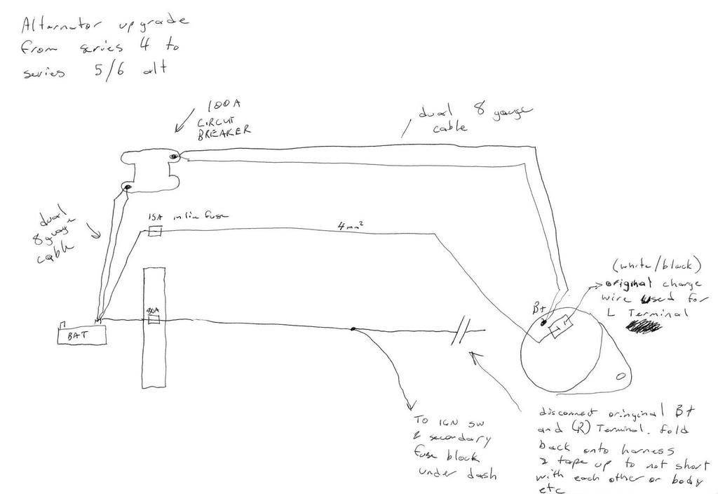
two months ago i did the FD into FC alternator conversion. (search the forums and it'll document how its done. it involves splicing some wires, taping everything, and machining a pulley for the FC style belt.)
anyways, the car was running really well, and might i add - much better on voltage than the FC (S4) alternator.
i drove this across country and it was hovering around 13.5-14.5 volts the entire time across the trip. everything was cool until I got to my destination, Portland
anyways- portland had a huge snow storm (by their terms) two weeks ago - and i parked the car
went back yesterday and the battery was totally dead - got a quick hot shot - had to do it three times because the car kept shutting off - on the third time it seemed to stay alive and the idle settled down - needless to say - i think the only problem i saw at this point was that on the voltage gauge, i saw a quick overshoot problem, where the voltage went up above 16v for a few seconds
the problems continued to get worse throughout the day - long story short, i got the car back to my house (towed). i charged the battery overnight - which is new - and tried again this morning. started the car up and the voltage now reads 12V, as-if the alternator is not operating properly.
i pulled the alternator - but i'm not sure whats up.
if i recall, the FD alternator has an "internal voltage regulator". the FC has an external regulator. in the process of doing the conversion (splicing, etc, etc) - the external regulator is "cut-out" of the loop.
so, perhaps at some point yesterday i blew the voltage regulator? perhaps i blew the alternator because the battery was dead and the old alternator couldn't handle charging so hard....
what do you guys think? i'm going to bring it the alternator to a shop later but wanted to check here first...
i figured this might be a good thread for us in the fc group
two months ago i did the FD into FC alternator conversion. (search the forums and it'll document how its done. it involves splicing some wires, taping everything, and machining a pulley for the FC style belt.)
anyways, the car was running really well, and might i add - much better on voltage than the FC (S4) alternator.
i drove this across country and it was hovering around 13.5-14.5 volts the entire time across the trip. everything was cool until I got to my destination, Portland
anyways- portland had a huge snow storm (by their terms) two weeks ago - and i parked the car
went back yesterday and the battery was totally dead - got a quick hot shot - had to do it three times because the car kept shutting off - on the third time it seemed to stay alive and the idle settled down - needless to say - i think the only problem i saw at this point was that on the voltage gauge, i saw a quick overshoot problem, where the voltage went up above 16v for a few seconds
the problems continued to get worse throughout the day - long story short, i got the car back to my house (towed). i charged the battery overnight - which is new - and tried again this morning. started the car up and the voltage now reads 12V, as-if the alternator is not operating properly.
i pulled the alternator - but i'm not sure whats up.
if i recall, the FD alternator has an "internal voltage regulator". the FC has an external regulator. in the process of doing the conversion (splicing, etc, etc) - the external regulator is "cut-out" of the loop.
so, perhaps at some point yesterday i blew the voltage regulator? perhaps i blew the alternator because the battery was dead and the old alternator couldn't handle charging so hard....
what do you guys think? i'm going to bring it the alternator to a shop later but wanted to check here first...
I dont really follow..lol..but if the regulator went out then it will over charge your battery and gets to look fat..lol..(it happened to me once) then the alternator dies out.
A car only has a battery just to start it up I believe. The alternator does the rest when the car is running.
A car only has a battery just to start it up I believe. The alternator does the rest when the car is running.

HAILERS
Joined: May 2001
Posts: 20,563
Likes: 27
From: FORT WORTH, TEXAS,USA
They both have internal regulators.
The regulator has to see batt voltage all day and night long. So you put your key in your pocket, then pull the small plug off the alternator, and with your digital meter, check to see if the S terminal wire has batt voltage on it.....or not.
And when checking the output of the alternator, you use a digital meter on the output post of the alternator...not the gauge in the car.
Last edited by HAILERS; Dec 30, 2008 at 05:33 PM.
Thread Starter
Full Member
Joined: Aug 2007
Posts: 147
Likes: 0
From: Portland, OR
Hey Hailers - I brought the alternator to a shop today. They plugged it in and tested it, and it outputted absolutely nothing. They also said from the sound of it, the rear bearing sounds shot (whatever - not sure if thats even true - but doesn't matter i suppose).
I guess I'm just trying to figure out why it died like this out of the blue.
Also, I used your diagram and previous explanation to do the conversion. It ran perfectly for about 4000-miles including a cross-country trip from Philadelphia to Portland. Its almost definitely not wire related is what i'm suggesting.
After I hook it up I'll see how it goes, but it still unsettles me...
Any idea?
HAILERS
Joined: May 2001
Posts: 20,563
Likes: 27
From: FORT WORTH, TEXAS,USA
As long as the small plug on the back side has batt voltage on it 24hrs a day, the thing should work if installed right. Installed right I suppose means belt aligned and not too tense nor too loose. That sort of thing.
The other wire on the back is just for the warning light and really shouldn't cause a problem if it alone was disconnect.
The other one could have been a rebuild with bad bearings. Who knows. Or the brushes inside it could have broke apart and got caught up in the works causing noise. Alt are not that hard to take apart to look at the brushes. Front pulley does not need removal. The Engine Elect section more or less shows how to take it apart. They use a soldering iron to heat the rear bearing holder.......I used a butane torch and played the heat on the bearing area til I got it as warm/hot as needed. Subjective thing. Burner on low.
The diagram is IceMarks.........I think. I just borrow it.
Last edited by HAILERS; Dec 30, 2008 at 11:25 PM.
*reallly knowing the fc
Joined: May 2007
Posts: 160
Likes: 0
From: victory lane
i have a related question. i don't know if this has been covered already but i doubt it. I have a 89 turbo alternator. it worked fine except that one day the wire (i forget the color) that comes from the idiot cluster and grounds in the alt rubbed the insulation off and the idiot lights stopped working. I thought i fried the circuit that lifts the ground and turns off the lights when the alt starts to produce volt/current. I had the alt rebuilt and now the lights work albeit very dimly. they work bright when i ground the wire to chassis. Is this problem related to the voltage regulator inside the alt?
And the main reason im writing is to find out if the fd alternator uses the same ground lift circuit for the idiot lights as the fc as i would like to upgrade. thanks
And the main reason im writing is to find out if the fd alternator uses the same ground lift circuit for the idiot lights as the fc as i would like to upgrade. thanks
HAILERS
Joined: May 2001
Posts: 20,563
Likes: 27
From: FORT WORTH, TEXAS,USA
A dimly lit warning light usually indicates one of the diodes in the alt is bad. Aren't I a little bearer of good news.
When the alt isn't producing that wire to the warning lights carries a gnd signal. When the alt starts producing, then the gnd isn't there any more. Magic.
I don't know what to say other than to not ground that wire because it's going to screw up the alternator imho. It's connected to the alt Field circuit.
I mean if it's connected to the alt don't gnd it. But if you pull the plug off the alt and then gnd it, it won't do any harm other than turn the warning light on.
Trending Topics
Full Member
Joined: Apr 2005
Posts: 167
Likes: 0
From: Sydney Australia
As long as the small plug on the back side has batt voltage on it 24hrs a day, the thing should work if installed right. Installed right I suppose means belt aligned and not too tense nor too loose. That sort of thing.
The other wire on the back is just for the warning light and really shouldn't cause a problem if it alone was disconnect.
The other one could have been a rebuild with bad bearings. Who knows. Or the brushes inside it could have broke apart and got caught up in the works causing noise. Alt are not that hard to take apart to look at the brushes. Front pulley does not need removal. The Engine Elect section more or less shows how to take it apart. They use a soldering iron to heat the rear bearing holder.......I used a butane torch and played the heat on the bearing area til I got it as warm/hot as needed. Subjective thing. Burner on low.
The diagram is IceMarks.........I think. I just borrow it.
The other wire on the back is just for the warning light and really shouldn't cause a problem if it alone was disconnect.
The other one could have been a rebuild with bad bearings. Who knows. Or the brushes inside it could have broke apart and got caught up in the works causing noise. Alt are not that hard to take apart to look at the brushes. Front pulley does not need removal. The Engine Elect section more or less shows how to take it apart. They use a soldering iron to heat the rear bearing holder.......I used a butane torch and played the heat on the bearing area til I got it as warm/hot as needed. Subjective thing. Burner on low.
The diagram is IceMarks.........I think. I just borrow it.
hi mate,
sorry been installing these for years.
the charge circuit needs to be connected as well as this is what tells the alternator to start/stop charging.
failing to connect all the terminals will make for a not happy alternator and the reason for seeing 12.3 to 16 volt iregularities.
read here -
http://www.ausrotary.com/viewtopic.php?f=16&t=33676
see this problem all the time
with all terminals connected you should get around 14.7 volts straight up when first starting the car. then after a long drive it should settle at 14.1 volts. that is a happy alternator.
cheers
Last edited by sim_rx3; Dec 31, 2008 at 06:03 AM.
HAILERS
Joined: May 2001
Posts: 20,563
Likes: 27
From: FORT WORTH, TEXAS,USA
Sorry 'bout that, but the L Terminal is NOT an input to the alternator. The L terminal is an OUTPUT from the alternator, not an input. The L terminal is the Field excitation wire from the regulator INSIDE the alternator.
See the diagram attached of a series six alternator out of the series six FSM. See the warning light circuit. See the blocking diode just before the warning light. See as how the blocking diode will not allow voltage into the alternator and only allows a ground to come OUT of the alternator to the warning light ...to turn the light on if the right conditions are met, as described at the bottom of the jpg.
IN other words the L wire could fall on the ground and the alternator will work just fine. You just lose the warning light and nothing else.
The S MUST be connected up to a constant, 24hrs a day wire from the battery on a series five/six.
Do as you please. Whatever floats your boat.
Last edited by HAILERS; Dec 31, 2008 at 09:11 AM.
HAILERS
Joined: May 2001
Posts: 20,563
Likes: 27
From: FORT WORTH, TEXAS,USA
The ENGINE ELECTRICAL section of S4/S5/S6 all have a fairly good section on trouble shooting the alternator. An example is the last jpg I attached in my last post above.
You can download the 94 FSM with the electrical trouble shooting section or the Series five section. They complement each other.
The Warning Light circuit on a series four is not exactly the same but on the whole works the same. It incorporates a relay b/t the warning light and the alt but works the same way for the warning light. A gnd output to the relay pulls it in and the relay then feeds batt voltage to the warning light (talking S4). The S5/S6 don't use the relay. Done.
Last edited by HAILERS; Dec 31, 2008 at 09:31 AM.
Full Member
Joined: Apr 2005
Posts: 167
Likes: 0
From: Sydney Australia
with all due respect
then please tell me why the alternator goes voltage stable ie 14.1 volts after the charge light circuit gets connected in place.
where in an install that doesnt gets from 12.3 volts to 16 volt outputs (which isnt good for the electrics or the regulator)?
also note im not attacking you im just saying from my experience in the game for over 10 years. connecting the charge circuit stabelises the voltage output and keeps the alternator happy.
which is the desired effect needed.
not connecting it usually means the reg dies after about 6 months ive seen..
by using the charge relay in the series 4 means no extra modifications on the harness. ie a keep it simple stupid mantality by me. as most of the guys doing these mods arent fully electrically trained. and the less butchering the better i say..
but upto you really..
HAILERS
Joined: May 2001
Posts: 20,563
Likes: 27
From: FORT WORTH, TEXAS,USA
Full Member
Joined: Apr 2005
Posts: 167
Likes: 0
From: Sydney Australia
the external diode is to stop back feed.
ive had it happen on an earlier model car that a forum user on ausrotary did the conversion on.
by not putting the diode in the charge circuit.
when you try to turn the car off with the key switch.
the car doesnt switch off, as everything is backfeeding the ignition circuit through the globe/alternator.
once the external diode was fitted the car shut off with the ignition switch as it was supost to..
HAILERS
Joined: May 2001
Posts: 20,563
Likes: 27
From: FORT WORTH, TEXAS,USA
The attachment I've attached is from this site: http://www.aa1car.com/library/charging_checks.htm
It tells how the light circuit works i.e. the L wire.
If the alternator isn't turning, then the negative side of the warning light gets a ground thru the Field wiring of the alternator. Once the alternator starts running, the ground is replaced by voltage and if there's equal voltage on each side of the warning light, then it won't light up.
Attached is a jpg of a series six alternator, similar to a series five.
On the other hand I looked at a site talking about BOSCH alternators that would lead one to believe that the light circuit, called D+ on Bosch alternators, supplies voltage thru the Field wiring when the alternator isn't running and that voltage is used for initial excitation of the alternator. So after reading that, I wonder a bit.
Right now my original series four turbo with the series five alternator on it , is putting out 13.8vdc while driving around. The light circuit is inoperative due to the usual half *** soldering by the factory in the Waring Light assy. Gotta do some soldering tomorrow after the epoxy I put on the broken soldering iron handle sets up good enough (probably made in the USA).
Anyway, someone asked on this thread or another as to what happens if the L wire is put to ground. It kills the field coil in the alternator is what happens and the alternator dies a sudden death.
I'm going to say I'm a little hesitant to say if the L wire is needed or not, other than for the warning light. My alt puts out 13.8 at idle with it disconnected. I may leave it disconnected just to see how life turns out. I don't need a warning light. I've a Palm and RTEK 2.0 to see the volgage on.
HAILERS
Joined: May 2001
Posts: 20,563
Likes: 27
From: FORT WORTH, TEXAS,USA
According to the jpg attached, I'm wrong. So make sure the L wire is indeed connected to the alternator. That said I've a small problem with this since I've a series five alt in my series four with the warning light not working and the alternator outputs immediatley on start up.
Thread Starter
Full Member
Joined: Aug 2007
Posts: 147
Likes: 0
From: Portland, OR
If this helps things out at all, the alternator shop told me the part which died was the "stater". They said the stater is a part related to the voltage regulator which dies from heat, and rarely dies from where and tear. I'm sure that because the battery was so low, the alternator was cranking really hard, and I let the car idle for like 30 minutes while I ran in and out of a building. I toasted it... almost surely...

Full Member
Joined: Sep 2005
Posts: 92
Likes: 0
From: Los Altos, CA
I've been reading this thread with much interest, since my FD modified for FC alternator is no longer charging reliability.
What might be the result of the L-wire being connected to 12v thru the relay, and the S-wire being disconnected? (that's what I believe I am seeing).
Pardon the thread jack.
What might be the result of the L-wire being connected to 12v thru the relay, and the S-wire being disconnected? (that's what I believe I am seeing).
Pardon the thread jack.
HAILERS
Joined: May 2001
Posts: 20,563
Likes: 27
From: FORT WORTH, TEXAS,USA
You must have the S wire connected to a permanent source of battery power. And connected to the correct terminal on the alternators jack.
The L wire on a series four goes to a relay in the CPU (series four) and supplys initial excitation thru the coil of that relay, not the contacts on that relay.
You should see all the warning lights light up when the key is to ON, engine OFF. What happens is the L wire puts ground on the relay in the CPU since it's not putting out voltage/current, and that causes the relay to pull in bringing the contacts together to supply a ground to the Warning Light Assy.
That L terminal is connected to the field circuit of the alternator. One end of the field circuit is grounded. That explains why it puts out a gnd signal when not producing power.
Once it produces power, the voltage is basicall the same on each side of the relay's coil (relay in CPU), so it does not pull in and the warning lights go out.
You gotta have batt pwr on the S terminal all day and night long. It's power to the regulator in the alternator.
Don't get confused as to which terminal is S and which is L. The jack on the alternator has a locking device at it's top. Look into it and the S goes to your left and the L to your right.
Even if you have power on the S terminal and no wire to the L, you might very well find that if you rev the engine to four or five grand, that the alternator will then put out from the *magnatism* in the rotor. From then on the field will be fed from the diode trio and hopefully controlled by the regulator in the alternator.
Acutally I just described a series four with series five or six alternator. IF you own something else, who knows. What exactly do you own. What year? What series. I probably shouldn't have written a thing since what I wrote is series four.
Anyway, look at your warning light assy with the L wire where it's supposed to be on the alternator. With key ON, engine OFF, do they all light up? or not. What happens if you take that L WIRE and put it to ground and key ON, engine OFF. Do the warning light all light up or not? Should. IF they don't, then you've some wiring to fix b/t the alt plug and the warning light assy.
IF you left the S wire off and just had the L wire on, and fed that L wire with batt voltage, the alternator would probably put out since your feeding the field thru the L wire. At least on a series four it would put out. I hesitate to pull the S wire off my cars and put batt voltage just to the L terminal. Alternators cost a bit.........but I've several spares................so ...........I .....................might............sometime.... .................................................. ..later..................maybe. Can't come up with a rational reason, for doing harm to my alternator. But then I've a few spares.
But if you did that, the field would not be regualted and you'd surely whack the alternator over a few weeks or so(guessing about the time period). And or you'd toast your battery imho over a period of time.
You need to put the wires where they belong and start the engine. Then see what the voltage output is on the large output terminal of the alternator. EVen better put the negative lead of you meter to the alternators case for the best reading of the output.
Seems to me the FD is just the same as the series five. I don't think they use a relay inside the warning light assy. I'm not sure one way or the other on that. On those the field gets excited thru the power going thru the warning light. You start the enging and the alternator initially starts putting out due to the power from that warning light. Once the alt puts out, the diode assy in the alternator feeds the field wiring and that results in the voltage on each side of the warning light to be basically the same so the light goes out. Something like that imho.
I'd never install a relay to supply 12vdc constant to the alternators L terminal (field). It's counterproductive.
Full Member
Joined: Sep 2005
Posts: 92
Likes: 0
From: Los Altos, CA
I have a '88 Vert with a 13BRE Cosmo conversion and a FD alternator.
If I place the alternator pully down, then the plug has the locking device facing up.
Then if I look into the plug with the locking device at the top, the wire to the left is the S-wire (according to your description) correct?
If that's correct then the S-wire is connected to a relay and the L-wire is loose.
HAILERS
Joined: May 2001
Posts: 20,563
Likes: 27
From: FORT WORTH, TEXAS,USA
Well I just went out and did what you suggested. I took the S wire off (has 12vdc all day long) and put it where the L wire goes on the alternator. Then left the L wire dangling in mid air.
Started and idled the car with a meter connected to the large B terminal on the alternator. Things looked normal. Voltage about 14.3. Good enough for my standards with a fully charged battery. Then I slowly, well kind of slowly rev'd the engine up to three grand. The voltage on the meter rose to 14.9vdc. Kept reving and the voltage went over 15vdc and was slowly climbing. So I let off the pedal. The voltage stayed at 15 and a bit. Not normal at all........'cause it isn't being regulated. It would probably gone down if I'd waited several minutes.
So what happens is your battery would eventually get over charges and die in ??? a few months? weeks?
I put the wires back where they belonged. Started the engine. Read in the 14.3 or so area. Rev'd the engine like before and the voltage climbe one or two tenths but nowhere near 15vdc or over.
Don't do what you seem to want to do. Counterproductive. Gonna waste the alt and the battery eventually.
Like I say, L wire feeds the field for initial starting, then the diode assy feeds the voltgage and the regulator varies that voltage to control the alternator. Must vary the voltage by varying the ground on the circuilt thru the regulator. Something like that imho.
Full Member
Joined: Sep 2005
Posts: 92
Likes: 0
From: Los Altos, CA
So, I guess my current question is which wire S or L is connected.
Your first diagram looks to me like the S-wire is the top connection (with the locking device to the right). That would seem to indicate that when unplugged and looking into the plug with the locking device on the top, the S-wire would be on the right and not on the left as you had indicated. Maybe I'm reading it incorrectly.
If it's the L-wire that's connected, then maybe I'm lucky and the battery is bad and all I need to do is wire-up the S and many replace the battery. Otherwise, the alternator could be bad.