
FD alt problem

I've checked the diodes test and it gave me 0.900V but when i start the cold engine and everything it gave me 11.8V so i believe alternator is already dead.
Thanks again HAILERS for the help
Thanks again HAILERS for the help
Former Moderator. RIP Icemark.
Joined: Apr 2001
Posts: 25,896
Likes: 24
From: Rohnert Park CA
Yep, see rather than thinking the owner is not following the well posted and easy to read instructions, I'd rather give the owner the benefit of doubt and instead blame the most likely issue... a bad alt.
After the FD alt install I've had problems with my battery draining overnight.
I used a multimeter to check the amps through the negative battery terminal and the negative clamp.
I tested the amps with the car off, I was getting like 0.2 amps with the car off.
After removing wire on the L terminal I get like .02...? Is the alt regulator shot?
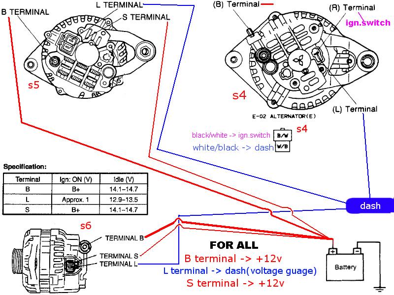
I wired as below.
I used a multimeter to check the amps through the negative battery terminal and the negative clamp.
I tested the amps with the car off, I was getting like 0.2 amps with the car off.
After removing wire on the L terminal I get like .02...? Is the alt regulator shot?
I wired as below.
As stated before with the L terminal connected I'm getting like 0.2A draw with the ign. off.
This leads me to belive this 'Alternator Swap Image' is not correct.
Maybe, the FD L terminal should pass through the IGN switch (R terminal) then to the dash. So that when the Ign switch is off, no power goes to the dash.
Or
The FD S terminal should run through the Ign, then to the batt.
Any suggestions?
I got the FD alt for cheap so I went this route.
I'm going to check out some things when I get home tonight.
If this diagram is incorrect I don't want other people, like me, thinking its correct.
Thanks!

HAILERS
Joined: May 2001
Posts: 20,563
Likes: 27
From: FORT WORTH, TEXAS,USA
Check it out to the series six pages attached. Came out of the series six Engine Electrical.
Last jpg is out of the series five Engine Electrical.
S wire goes to the EGI fuse on a series five. Bascically the same as going the the B terminal since the B terminal feeds the engine bay fuse box....where the EGI fuse resides.
Last jpg is out of the series five Engine Electrical.
S wire goes to the EGI fuse on a series five. Bascically the same as going the the B terminal since the B terminal feeds the engine bay fuse box....where the EGI fuse resides.
I think they do, but my idiot light cluster is wack, lights flicker and stuff.
I'm no EE, but why couldn't I hook the FD alt 'L' Terminal to the S4 'R' Terminal?
But looking at it again, seems that it should work with the L to the L? hmm....
FD alt 's' could go the the 'r' maybe?
Thanks!
I'm no EE, but why couldn't I hook the FD alt 'L' Terminal to the S4 'R' Terminal?
But looking at it again, seems that it should work with the L to the L? hmm....
FD alt 's' could go the the 'r' maybe?
Thanks!
Full Member
Joined: Apr 2005
Posts: 167
Likes: 0
From: Sydney Australia
OK, I got the Alternator tested, it is good. I'm trying to swap an s6 alt to s4.
As stated before with the L terminal connected I'm getting like 0.2A draw with the ign. off.
This leads me to belive this 'Alternator Swap Image' is not correct.
Maybe, the FD L terminal should pass through the IGN switch (R terminal) then to the dash. So that when the Ign switch is off, no power goes to the dash.
Or
The FD S terminal should run through the Ign, then to the batt.
Any suggestions?
I got the FD alt for cheap so I went this route.
I'm going to check out some things when I get home tonight.
If this diagram is incorrect I don't want other people, like me, thinking its correct.
Thanks!
the diagram is correct.
read back through the thread about a "little diode" that has been spoken of. its dead. so power now back feeds through the alt and is a parasidic load while the car is off..
HAILERS
Joined: May 2001
Posts: 20,563
Likes: 27
From: FORT WORTH, TEXAS,USA
Naw. The FD L should go to your old white/black wire on the series four harness.
The half *** Mazda Warning Light cluster really does not matter all that much since it's a known defective part that needs repair tooooo much on tooooo many car. The L wire on a series four goes to a relays coil in the CPU. Here's what you do. Turn the key ON with the white/black wire off the alternator. See if the black/white wire has approx batt voltage on it. Say YES IT DOES!
Now with the key ON touch that white black wire to a known ground point........like the body of the alternator. Listen carefully. You should hear the relay in the CPU click each time you put that white/black wire to gnd. I know I can hear it from the alternator area so you should be able to hear it also. Not that it really matters all that much if it has the batt voltage on it. But hearing the click of the relay confirms the relay is ??? there?? good?? or the wiring b/t the black/white wire at the alternator is not open b/t the CPU and the alternator terminal.
On a series four the batt voltage on the white/black comes thru a relays coil IF the dwg is right. I wonder sometimes. Send me a old series four CPU and I see how true that is. I'm not going to tear my CPU up.
So anyway, put that white black wire to the L terminal on the alternator. Looking into the alternators jack, it would be the terminal to the RIGHT.
Then just crimp on a female spade connector to the terminal on the alternators jack. The LEFT terminal..Run the other end of wire to the engine bay fuse box. Not a straight run of wire but route it so it won't be in the way. Done.
Icemark says you can run the black/white to the terminal on the left. If your so inclined go do that instead and the white/black to the right terminal on the alternator.
Right and left are ..............looking into the alternators jack with the locking devive of the jack on top. I pasted a jpg of right/left on the alt jack in a post waaaaay above this one.
Full Member
Joined: Apr 2005
Posts: 167
Likes: 0
From: Sydney Australia
you ask them what they have connected and they say something other than the diagram shows. how can you give them the benifet of the doubt??
aspecially when they come back with questions that contradict the diagram.
ie 1 i should connect the R wire to the L terminal
ie 2 i should just make a short jumper from the L terminal to the B+ terminal as its the same.
yet different cases it is done time and time again, but it is not shown on the diagram.
not connecting it like the diagram does make the alternator play up (and in some cases toast the reg)..
how is it not the installers fault??
https://www.rx7club.com/showpost.php...3&postcount=12
Didn't see that post.
I got the alt tested today, they said its good... But if i test it as above: meter set to diode test, hooked (negative)black lead to the alternator output to battery, ground the positive(red) lead, I get OL. Nada...?
I'm not trying to be a idiot. But, Hey your lucky I didn't start another thread! J/k...
Ok, I'm now officially a tard. I think the L and S was swapped.
"The half *** Mazda Warning Light cluster really does not matter all that much since it's a known defective part that needs repair tooooo much on tooooo many car. The L wire on a series four goes to a relays coil in the CPU. Here's what you do. Turn the key ON with the white/black wire off the alternator. See if the black/white wire has approx batt voltage on it. Say YES IT DOES!"
That wire's taped off tho....
Thanks, flame on.
HAILERS
Joined: May 2001
Posts: 20,563
Likes: 27
From: FORT WORTH, TEXAS,USA
************************************************** *************************UNDER ALL CIRCOMSTANCES DO NOT DO THIS!!!!
have a look at the original wiring diagrams for the series 5/6. were does it get its supply - from the battery
there is a reason for this. an alternator doesnt put out true DC volts.. its the battery that keeps it a constant DC voltage.
i tried this actual install when i first started installing them into early mazdas(connecting S to B+) and we had issues with the voltage spiking to 16 to 17volts on some cars (its called limp mode).
basically cause the input for the S terminal was getting a "dirty signal" the regulator would go haywire..
so definetly do not do this as it might look like - same, same but different. it is definetly far from it..
************************************************** ************************************************** ***********************************************
The above should never be written. It's wrong. The alternator puts out dc voltage. And the B wiring goes to the same buss on the engine bay fuse box that the EGI fuse is connected to.
The B wiring feeds attaches to the engine bay fuse box at the aft bolt that holds the Main Fuse.....the power goes thru the Main fuse to feed the buss bar on the front side of the engine bay fuse box. That's where the fuses in that box get their power. Like the EGI fuse. So you can see they are all tied together. There is no seperation of the EGI fuse from the B terminal wire unless the Main Fuse blows. Any time that alternator is putting out, IT is the one that is feeding the engine bay fuse box fuses, NOT the battery. Much like the IG1 and IG2 fuses in the interior are not fed from the battery when the alternator is working. Those are being fed by the alternator thru the ignition switch which gets it's power from..........the wiring that goes to the B terminal on the alternator.
You can see that in the two jpgs I attached in post #55 or just go look at any series 4/5/third gen.

Thread
Thread Starter
Forum
Replies
Last Post
The1Sun
1st Generation Specific (1979-1985)
7
Sep 18, 2015 07:13 PM