
FD alt problem

Thread Starter
Card-carrying Rotorhead
Joined: May 2006
Posts: 457
Likes: 0
From: Quebec
FD alt problem
I installed an FD alt in my s4 turbo'd GXL last spring and it doesn't seem to be performing as well it should. First off, the only additional engine-related electronic devices I'm running are, PLX wideband, AFC neo, Fiero electric fan, everyting else is stock.
Here's the problem (all voltages measured using afc neo)...
When I start the car cold, voltage is ~14.3 (I was expecting this to be normal for this alt)
Once the car warms up ~13.5
When the electric fan cuts in, it drops to ~12.7 then comes up to ~13.1
When I slow down (brake lights on) to a stop at night (headlights on), with the engine warm and e-fan running ~11.5 (at this point it really wants to stall)
These numbers are for an average day (25*C) under normal driving.
I just had the alt tested at a local shop and it produced 125amps
Something doesn't seem to add up here
I know my engine has a shot coolant seal so it runs pretty warm to begin with and the turbo doesn't help the heat situation. Can high underhood temps affect voltage that much?
I am plannig to get a vented hood eventually (vmount), how much would this lower underhood temps?
The only thing I can think of is to take the alt apart and check /replace bearings and brushes and see if that makes a difference.
Any suggestions?
Former Moderator. RIP Icemark.
Joined: Apr 2001
Posts: 25,896
Likes: 24
From: Rohnert Park CA
Alt is starting to fail. The shop probably checked it when cold. Try replacing brushes and the regulator.
Of course that reply is based on the idea that you installed and wired the FD alt correctly for your car.
Of course that reply is based on the idea that you installed and wired the FD alt correctly for your car.
Full Member
Joined: Apr 2005
Posts: 167
Likes: 0
From: Sydney Australia
hi,
your issue is the conversion..
series 4 alt is a resistive load alt
series 5 is a load sensative alt
both are connected in different ways, a load sensative alt needs all its connection to be entirely correct for it to work properly....
by not connecting the load sensative alt proprly the voltage output is "floating".
THE VOLTAGE IT PUTS OUT SHOULD BE A FLAT 14.1 VOLTS NO MATTER WHAT.
connect it right and the problem will be gone..
keep running it like this and the regulator will toast itself and dead alternator you will have.
this is the thread you should have read - https://www.rx7club.com/showthread.ph...ght=alternator
i even explain your exact issue -
just do the wiring mod as i have shown below and your alt (providing the regulator isnt already toast) will be happy again
cheers
your issue is the conversion..
series 4 alt is a resistive load alt
series 5 is a load sensative alt
both are connected in different ways, a load sensative alt needs all its connection to be entirely correct for it to work properly....
by not connecting the load sensative alt proprly the voltage output is "floating".
THE VOLTAGE IT PUTS OUT SHOULD BE A FLAT 14.1 VOLTS NO MATTER WHAT.
connect it right and the problem will be gone..
keep running it like this and the regulator will toast itself and dead alternator you will have.
this is the thread you should have read - https://www.rx7club.com/showthread.ph...ght=alternator
i even explain your exact issue -
failing to connect all the terminals will make for a not happy alternator and the reason for seeing 12.3 to 16 volt iregularities.
just do the wiring mod as i have shown below and your alt (providing the regulator isnt already toast) will be happy again
cheers
Former Moderator. RIP Icemark.
Joined: Apr 2001
Posts: 25,896
Likes: 24
From: Rohnert Park CA
this is the thread you should have read - https://www.rx7club.com/showthread.ph...ght=alternator
i even explain your exact issue -
i even explain your exact issue -
just do the wiring mod as i have shown below and your alt (providing the regulator isnt already toast) will be happy again
This is the correct way to wire the alt (as found in the 2nd gen archive as well as the FAQ for FC and countless threads):
Thread Starter
Card-carrying Rotorhead
Joined: May 2006
Posts: 457
Likes: 0
From: Quebec
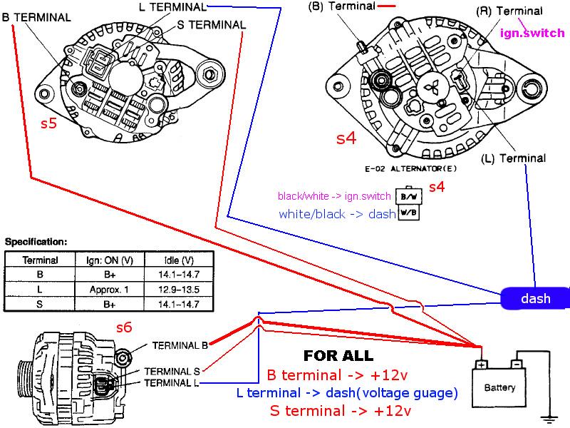
When I wired the alt up i followed the diagrams listed in the FAQ but just to be sure...
In that diagram for the s4 alt, the (R) Terminal / ign.switch would get connected to the Terminal S on the FD alt, correct?
In that diagram for the s4 alt, the (R) Terminal / ign.switch would get connected to the Terminal S on the FD alt, correct?

HAILERS
Joined: May 2001
Posts: 20,563
Likes: 27
From: FORT WORTH, TEXAS,USA
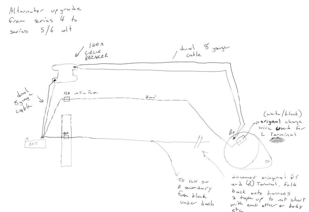
No. The R wire would have been colored BLACK/WHITE and would be tied back to the harness and tapped over. Never to be used again.
The L wire would go to the RIGHT side of the connector. The L wire is WHITE/BLACK.
The S would be a NEW wire and connected to the LEFT terminal on the alternators jack and the other end of that NEW wire would go to the battery, preferably with a fuse inbetween.
I attach a simple dwg of what it should look like. I think some don't know the L from the S. So I made a dwg of the jack on the alternator showing how you determine which is which.
Joined: Aug 2001
Posts: 6,096
Likes: 9
From: So Cal where the OC/LA/SB counties meet
Mark,
You know I follow your advise as if it were holy gospel. However;
1. The wiring diagram in the FSM indicates a 30 amp fuse between the battery and the S terminal. So I went with the same 30 amp fuse when I wired my FD alternator into my S4.
2. Further, I ran the wire from the S terminal all the way to the battery terminal instead of simply to the B terminal on the alternator which obviously flows to the exact same place.
Factory overkill, or what?
Link is bad
a 15 amp fuse on that wire is insane. At the most a 5 amp fuse is all that its needed. It is a voltage reference, not a feed and in fact you can solve the whole issue (if it is wired incorrectly) with a 3 amp diode.
This is the correct way to wire the alt (as found in the 2nd gen archive as well as the FAQ for FC and countless threads):
Trending Topics
Full Member
Joined: Apr 2005
Posts: 167
Likes: 0
From: Sydney Australia
Link is bad
a 15 amp fuse on that wire is insane. At the most a 5 amp fuse is all that its needed. It is a voltage reference, not a feed and in fact you can solve the whole issue (if it is wired incorrectly) with a 3 amp diode.
This is the correct way to wire the alt (as found in the 2nd gen archive as well as the FAQ for FC and countless threads):
a 15 amp fuse on that wire is insane. At the most a 5 amp fuse is all that its needed. It is a voltage reference, not a feed and in fact you can solve the whole issue (if it is wired incorrectly) with a 3 amp diode.
This is the correct way to wire the alt (as found in the 2nd gen archive as well as the FAQ for FC and countless threads):
try this - https://www.rx7club.com/showthread.p...ght=alternator
with all due respect. ive been installing these in cars for over 10 years (check signature, im an auto electrician). i.ve seen all sorts of issues and they all come back to one thing. incorrect connection or failed components in the alt.
your diagram is vertically what i have shown in my diagram if you compare.
the difference is by not tieing back the original B+ (which is rated for the original alt) and why the wiring mod was done in the series 5 for the extra capacity.
you run the risk of difference of more than 1 volt between B+ and S terminal of a load sensitive alternator by not upgrading the B+ as well.
this creates limp mode in the alternator and the volts shoots to 16 volts.
my diagram is how i connect any series 4 or earlier rx with a series 5/6 alternator.
new wires straight from the battery for the B+ and S terminal and the cars original charge circuit is connected to the L terminal.
when you first run the car the car charges at 14.7 volts as the battery in a resistive system charges slightly lower so the system is trying to catch up.
when you then taken the car for a decent drive the voltage will sit at a constant 14.1 volts stable and wont waver..
while your at it read this thread as well - http://www.ausrotary.com/viewtopic.php?f=16&t=33676
ive dealt with it all..
its not a new problem its been around for ages as people dont understand the system and doing whats needed to make the upgrade reliable..
im only giving you info from my experience. do with it what you will
cheers
this is a good thread as i am just getting ready to install my fd alternator into my S4. however i have some wiring problems from the previous owner.. the battery is installed in the back. then he has a 0 gauge wire from battery to the starter then a 4 gauge wire from the same post on starter to the factory underhood 50amp fuse circut then the other side of that 50amp fuse goes to the alternator. i think the other two small wires go to the original location. this cant be good but it seems to work fine other then i noticed the factory 50amp fuse looks black like it gets really hot. can anyone help me here before i start my own thread?
HAILERS
Joined: May 2001
Posts: 20,563
Likes: 27
From: FORT WORTH, TEXAS,USA
The first jpg below should have been good enough for anyone to install the series five or six alternator into a series four.
I add the secondd jpg below, because some people are having problems, and I suspect the problem is they're accidently getting the S and L wires crossed when put on the alternator, so I tried to show the top of the alternators jack and location of the S and L wires. But they're already shown pretty good on the first jpg of ????? IceMark?.
Other than getting the L and S wires crossed on the alternator, it seems to some it's not clear that you need to tie back the original BLACK/WHITE wire to the harness, and that it won't get used.
The OTHER problem might be that some are buying used series five or six off this forum and they're already toast prior to the install. Shame on the sellers and a pox on their children.
The series five car has ONE EGI fuse,and if you look you'll see on a series five the S wire goes to that single EGI fuse. That EGI fuse does more than protect the alternator though. So to me it seems you should install a fuse to protect the alternator. But then again it's not a MUST for the installation. I ran mine to the engine bay fuse box instead of the battery.
Again, the first jpg, the red, white and blue one, should have been good enough.
Thread Starter
Card-carrying Rotorhead
Joined: May 2006
Posts: 457
Likes: 0
From: Quebec
...crap I think I wired my alt up wrong.
I just made 2 jumper wires and connected the two spots on the harness plug to the 2 prongs on the alt, so the (L) to (L) was correct but the (R) to (S) isn't.
I just made 2 jumper wires and connected the two spots on the harness plug to the 2 prongs on the alt, so the (L) to (L) was correct but the (R) to (S) isn't.
Former Moderator. RIP Icemark.
Joined: Apr 2001
Posts: 25,896
Likes: 24
From: Rohnert Park CA
The OTHER problem might be that some are buying used series five or six off this forum and they're already toast prior to the install. Shame on the sellers and a pox on their children.
The series five car has ONE EGI fuse,and if you look you'll see on a series five the S wire goes to that single EGI fuse. That EGI fuse does more than protect the alternator though. So to me it seems you should install a fuse to protect the alternator. But then again it's not a MUST for the installation. I ran mine to the engine bay fuse box instead of the battery.
So a 15 or 30 amp fuse on a circuit that dies with 4 amps is radically overkill. But if you mis-run the wire and it rubs through to a ground, a 18 awg or 20 awg wire will melt long before the fuse blows. So the fuse is not protecting the alt- it is protecting the wire.
So it is again beyond me, with how many diagrams and threads on this in the archives here and other boards and even in the FAQ for FC here that people can still get this wrong.
And I am merely saying that the fusing and wiring you are suggesting is overkill and probably not protecting the wiring. Remember fuses are to protect the wiring not the component. It is up to the component designer to include protection from voltage spikes (both directions) and the internal workings (which they do 99% of the time).
BTW: It is commonly accepted that a less than 15 ft wire run with fine stranded wire (such as used for most automotive stereo installations) that a 12/15 volt single phase is running through that a 8 awg wire is capable of handling 150 amps through it, so by your diagram using two 8 awg wires, you are maxing the capability to 300 amps... far more than any conventional alternator will ever allow.
Now if you are using thick strand that drops considerably, and if you are using solid core that drops down to only 73 amp (based on the National Electrical Code, the maximum Amps for Power Transmission uses the 700 circular mils per amp rule, which is very very conservative).
Joined: Feb 2006
Posts: 2,897
Likes: 2
From: Renton/Bellevue/Seattle WA
What about for people that have removed their stock wiring harness and don't have the stock wire for L that goes to the dash. (such as a haltech or standalone install) I currently have it getting power from my ignition switch. I am assuming that the dash gives a slightly lower voltage signal that just the battery/ignition because I get slightly lower volts. (13.8 idle then 14.1 any time other than idle). How would recommend I get the proper L dash signal in this situation.
Thanks.
Thanks.
HAILERS
Joined: May 2001
Posts: 20,563
Likes: 27
From: FORT WORTH, TEXAS,USA
Well according to the post just below Yours, there is no problem. So keep on truck'in. Only worry if you have a battery that drains over a period time. Sorry is I worried you.
Thread Starter
Card-carrying Rotorhead
Joined: May 2006
Posts: 457
Likes: 0
From: Quebec
So then you can wire it 2 ways?
1. Connect the ign.switch wire to the (S) terminal on the FD alt
2. Ignore the ign.switch wire, and just connect the (S) terminal directly to the battery (with a fuse).
1. Connect the ign.switch wire to the (S) terminal on the FD alt
2. Ignore the ign.switch wire, and just connect the (S) terminal directly to the battery (with a fuse).
HAILERS
Joined: May 2001
Posts: 20,563
Likes: 27
From: FORT WORTH, TEXAS,USA
According to IceMark above, you could take your White/Black wire and put it to the right side of the series five alternator (L terminal). You'd then put your Black/White wire to the left side of the series five alternator (S terminal).
Or you could tie the black/white back to the harness and not use it at all and run a new wire from the battery or engine bay fuse box, to the S terminal (left terminal on the series five alternator). And use the white/black wire on the right terminal of the series five alternator.
You seem to have used the black/white and white/black wires and no newly run wires and if you connected them right you should be ok. As in the white/black to the right terminal on the series five altenator and the black/white to the left terminal on the alternator.
That make any sense????
Are you having any alternator problems? Any battery drain problems?
FYI: When I say right or left side of the alternator, I'm referring to the electrcal jack on the alternator. And I consider the locking device to be at the top of the jack and therefore the S terminal is on the left and the L terminal is on the right. I'm talking about looking straight into the jack with the locking device on top.
If you have any battery drain problems, the go with tieing the black/white wire back to the harness and not use it, but run the new wire to the battery or engine bay fuse box.
HAILERS
Joined: May 2001
Posts: 20,563
Likes: 27
From: FORT WORTH, TEXAS,USA
EDIT: Well if it's switched power, then I see no need for a diode. SECOND EDIT: I thought they had a resistor in there, but on second look it's just their method of dwg a relay that confused me. But you can see that the voltage passes thru a relay's coil (not the contacts but the coil), and if I remember that is like a 65 ohm relay coil. So either it makes me think that power needs to pass thru a resistor of approx 65ohms. I'm doing the 65ohms from memory.
I'm just trying to ape the original path of power.
I thought the OZ man had posted a dwg of what you wanted. I'll see if that's so or not.
HAILERS
Joined: May 2001
Posts: 20,563
Likes: 27
From: FORT WORTH, TEXAS,USA
Something like this:
EDIT: Well if it's switched power, then I see no need for a diode. SECOND EDIT: I thought they had a resistor in there, but on second look it's just their method of dwg a relay that confused me. But you can see that the voltage passes thru a relay's coil (not the contacts but the coil), and if I remember that is like a 65 ohm relay coil. So either it makes me think that power needs to pass thru a resistor of approx 65ohms. I'm doing the 65ohms from memory.
I'm just trying to ape the original path of power.
I thought the OZ man had posted a dwg of what you wanted. I'll see if that's so or not.
Try that at your own risk. What happened to your original CPU???? and wiring? All gone?
Joined: Feb 2006
Posts: 2,897
Likes: 2
From: Renton/Bellevue/Seattle WA
 Its just the haltech wiring for everything needed to run. (Injectors, coolant air temp, TPS sensors, cas wiring and 3 wires to ignition ect..)
 I had a feeling that there was some sort of resistance on that L port because the manual says 12.9-13.5V not the normal 14.1-14.7 volts. So I am giving it the full voltage in my system, and it turns down the output of the alternator because it is not getting the nerfed signal.
Thank you Hailers.
Now, could someone with a spare ECU chilling around, could you possibly measure and confirm the resistance please?
Thanks.
~Tweak
(I guess I could get a variable resistor (potentiometer) and slowly add resistance until I get the perfect 14.4 volts output (Maybe even 14.6
). Then I could use my DMM and find out what resistance I am at and go get a nice high quality resistor to permanently install.)
Former Moderator. RIP Icemark.
Joined: Apr 2001
Posts: 25,896
Likes: 24
From: Rohnert Park CA
Something like this:
EDIT: Well if it's switched power, then I see no need for a diode. SECOND EDIT: I thought they had a resistor in there, but on second look it's just their method of dwg a relay that confused me. But you can see that the voltage passes thru a relay's coil (not the contacts but the coil), and if I remember that is like a 65 ohm relay coil. So either it makes me think that power needs to pass thru a resistor of approx 65ohms. I'm doing the 65ohms from memory.
I'm just trying to ape the original path of power.
I thought the OZ man had posted a dwg of what you wanted. I'll see if that's so or not.
EDIT: Well if it's switched power, then I see no need for a diode. SECOND EDIT: I thought they had a resistor in there, but on second look it's just their method of dwg a relay that confused me. But you can see that the voltage passes thru a relay's coil (not the contacts but the coil), and if I remember that is like a 65 ohm relay coil. So either it makes me think that power needs to pass thru a resistor of approx 65ohms. I'm doing the 65ohms from memory.
I'm just trying to ape the original path of power.
I thought the OZ man had posted a dwg of what you wanted. I'll see if that's so or not.
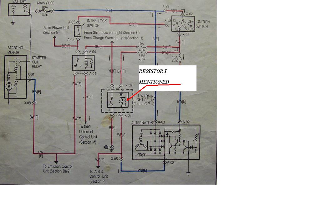
The resistor is just a coil and surge resistor that keeps spikes out... that's it. Almost every relay (everywhere in the car, not just in the CPU) that Mazda specifies has either a capacitor or resistor for spikes. So the resistor means nothing as well.
When the alt fails or voltage drops off, the ALT grounds the wire which turns the relay on, and it activates the warning lights.
That is all it does. So if you have removed your body computer (CPU) and wired past the horn relay. brakes lights, turn signals, etc, then you don;t need the wire at all... it does nothing but report alt failure.
Um... yes lol. Its a haltech e11v2 standalone install. Its just the haltech wiring for everything needed to run. (Injectors, coolant air temp, TPS sensors, cas wiring and 3 wires to ignition ect..)
I had a feeling that there was some sort of resistance on that L port because the manual says 12.9-13.5V not the normal 14.1-14.7 volts. So I am giving it the full voltage in my system, and it turns down the output of the alternator because it is not getting the nerfed signal.
Thank you Hailers.
Now, could someone with a spare ECU chilling around, could you possibly measure and confirm the resistance please?
Thanks.
~Tweak
Its just the haltech wiring for everything needed to run. (Injectors, coolant air temp, TPS sensors, cas wiring and 3 wires to ignition ect..) I had a feeling that there was some sort of resistance on that L port because the manual says 12.9-13.5V not the normal 14.1-14.7 volts. So I am giving it the full voltage in my system, and it turns down the output of the alternator because it is not getting the nerfed signal.
Thank you Hailers.
Now, could someone with a spare ECU chilling around, could you possibly measure and confirm the resistance please?
Thanks.
~Tweak
S4 alt has two wires... one for voltage that the alt references... this wire goes to ignition. The second wire is for the CPU to tell the idiot lights to turn on when the alt is not spinning but ignition is on.
So again, a Haltech means nothing in regards to the alternator operation.
Now if you chopped off the wire that feeds the CPU from the alt, then either you re-run the wire, of you do not have any sort of indication of if the alt fails. That's all!
Joined: Feb 2006
Posts: 2,897
Likes: 2
From: Renton/Bellevue/Seattle WA
ok .... weird. I will have to do some testing tomorrow. I am going to unplug my L, and see what happens. My L is getting ignition too........ IF I remember correctly I had to do that, or else it would just sit at 15v all day long. I will let you know tomorrow.
Thread Starter
Card-carrying Rotorhead
Joined: May 2006
Posts: 457
Likes: 0
From: Quebec
No I don't think I was having any battery draining problems, my car is parked right now so I can't really check. Maybe just to be safe I'll wire it the other way(S straight to the battery w/fuse).
Former Moderator. RIP Icemark.
Joined: Apr 2001
Posts: 25,896
Likes: 24
From: Rohnert Park CA
The L lead on a S4 rests at ignition with the Key on, and is dead when the key is off.
Again it has nothing to do with the alt's output... it is the lead from the dash to work the idiot lights and charge fail lights.
Again you could run the alt just fine without it even being hooked up... it is only for the CPU or idiot lights, and it works simply by that if the alt is not spinning, the alt puts ground on the terminal that the L wire is hooked up too. This ground completes the circuit in the CPU or in the Idiot light panel or in the dash panel (depending on Series) and turns on the idiot light(s).
HAILERS
Joined: May 2001
Posts: 20,563
Likes: 27
From: FORT WORTH, TEXAS,USA
Until recently I thought the L wire was for nothing more than causing the warning lights to come on.
I changed my mind for several reasons. Like one thing I did to prove/disprove that idea, was to go to my series four alternator and remove the L wire but left the black/white on the alternator. Started the car with meter attached to the B terminal. Only had 12vdc.
Rev'd the engine and then the volgage went to the mid 14's and stayed there. The field now was being fed by the diode trio which explains why it now worked.
You know in the Engine Electrical secton of each series, there is a TEST where you turn the key On, engine OFF. Then probe the L wire with it connected to the alternator. You should see 1-3vdc. Well that 1-3vdc has to be coming from the L wire itself. If you pull just the L wire off and probe the L terminal on the alternator itself, you will not see any voltage. IT comes from the L Wire.
The L Wire has batt voltage on it coming from the relay coil on a series four car. IF you connect the L wire to the alternator, it is now connected to the field coil of the alternator and the batt voltage gets pulled down to the 1-3vdc (my assumption) you see when you probe the L wire with it connected to the alternator and key ON.
I just now, not more than thirty minutes ago, tried this on the series five alt on a series four car. I pulled the intercooler off to access the alt wiring. I pulled the L wire off the alternator. Then started the car with the meter connected to the B terminal of the alternator. Only 12vdc shows up on the meter when the car started. Rev'd the engine a bit and it went Close to the 15vdc range.
Shut the engine off. Reconnected the L wire to the series five alternator. Started the car. Voltage was in the mid 14's vdc.
Shut the car off, key to ON. PUlled the L wire off the alternator and left the S wire on. Probed the L terminal on the alternator. No voltgage. Put the L wire back on the alternator with key ON, engine Off. Probed the L wire with a needle. It has close to 1vdc (field voltage).
So while just a few weeks ago I thought the L wire was only for the warning lights, I convinced myself that is not the case. I was wrong. The L wire has to be first of all feeding the Field of the rotor for initial excitation of the alternator.
I hesitated to suggest to TWEAK what to do. I'm no expert. I'd first of all suggest using the stock wiring for the L wire. Comes from the CPU. But his car seems to have a bit of wiring missing (assumption). And I hesitate to say just run straight batt power to the L wire since that isn't the case with the series four wiring. I'm not talking about the key switch/fuses etc, I'm talking about how that batt voltage is passing thru the alt relay coil which is of ????? ohms (think resistor). I said 65 but it might be higher.
I shouldn't have answered TWEAK.
But consider what I wrote about the L wire above. How the alternator does not get excited if your missing it. And if it off and you rev the engine and now it's excited, how the voltage output is quite a bit higher than normal. Not kosher.
And I don't trust the wiring diagrams of the guts of the series five alt. In the wiring diagrams it shows one thing. In the Engine Electrical it shows a big black section with the internals of the regulator all blacked out. Not trust worthy.
In the jpg attached with the 1-3 vdc L wire test, and the suggestions as to what is wrong if you don't get that figure, it mentions the rotor coil. The rotor coil is the field.