
FD alt problem


HAILERS
Joined: May 2001
Posts: 20,563
Likes: 27
From: FORT WORTH, TEXAS,USA
Tweak, tell you what. I've some spares so I can lose an alternator and not be hurt. I'll just not use the stock L wire and make my own configuration and let you know how that turns out. Might take til tomorrow. Maybe not.
Former Moderator. RIP Icemark.
Joined: Apr 2001
Posts: 25,896
Likes: 24
From: Rohnert Park CA
Until recently I thought the L wire was for nothing more than causing the warning lights to come on.
I changed my mind for several reasons. Like one thing I did to prove/disprove that idea, was to go to my series four alternator and remove the L wire but left the black/white on the alternator. Started the car with meter attached to the B terminal. Only had 12vdc.
I changed my mind for several reasons. Like one thing I did to prove/disprove that idea, was to go to my series four alternator and remove the L wire but left the black/white on the alternator. Started the car with meter attached to the B terminal. Only had 12vdc.
Your tests do show a bad diode between the two, but I suppose that the alt can get excited from it somehow... just don't see it in the alt or it's diagram.
HAILERS
Joined: May 2001
Posts: 20,563
Likes: 27
From: FORT WORTH, TEXAS,USA
Well congratulate me. The fine little alternator that this morning put out 1-3 vdc on the L wire when the key was ON, engine OFF, and put out 14.3vdc at idle, now has turned into a typical piece of carp alternator that puts out maybe 13.5 vdc and the L wire now shows 10vdc with key ON, engine OFF. Time for a new regulator/brushes. I left the L wire off unknowingly for a period time (read Dumbass had the CPU out of the car and.....forgot it. While I was rigging up an alternate source of power for the L wire).
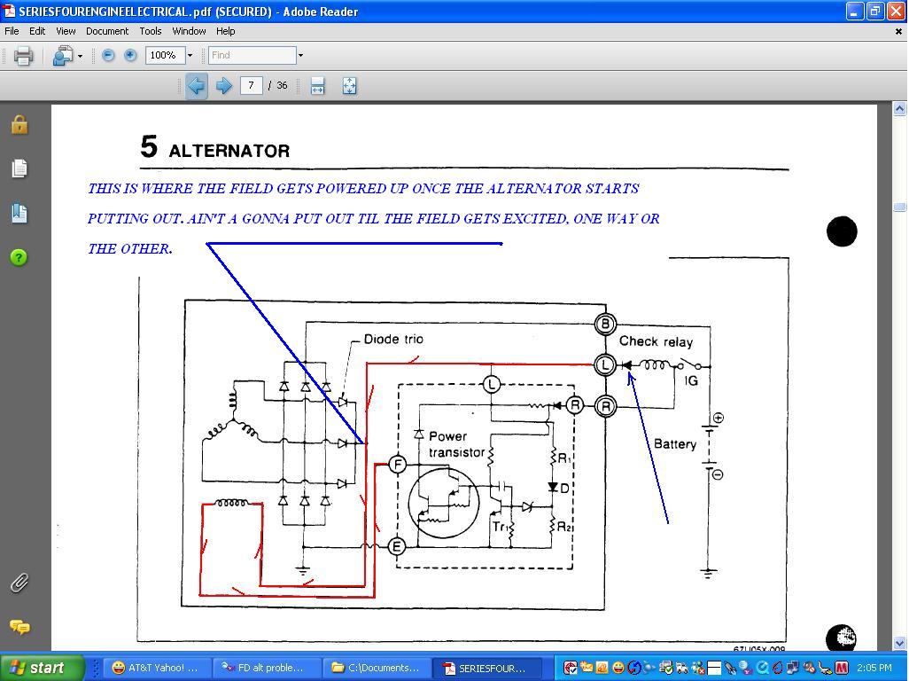
See the jpg attached. See how the voltage goes from the CPU alt relay coil, thru the diode to the Field of the alternator. That gets the thing going initially. If you leave the L wire off, there is no field voltage, UNLESS you rev the engine and then the residual magnatisim in the rotor self starts it.
I"m out of the alternator advice business.
Joined: Feb 2006
Posts: 2,897
Likes: 2
From: Renton/Bellevue/Seattle WA
Well congratulate me. The fine little alternator that this morning put out 1-3 vdc on the L wire when the key was ON, engine OFF, and put out 14.3vdc at idle, now has turned into a typical piece of carp alternator that puts out maybe 13.5 vdc and the L wire now shows 10vdc with key ON, engine OFF. Time for a new regulator/brushes. I left the L wire off unknowingly for a period time (read Dumbass had the CPU out of the car and.....forgot it. While I was rigging up an alternate source of power for the L wire).
See the jpg attached. See how the voltage goes from the CPU alt relay coil, thru the diode to the Field of the alternator. That gets the thing going initially. If you leave the L wire off, there is no field voltage, UNLESS you rev the engine and then the residual magnatisim in the rotor self starts it.
I"m out of the alternator advice business.
hmmm... ok I really am trying to understand this. It sounded like, you blew an alternator (or weakened it considerably?) because you didn't have the L wire connected? (because you didn't have the car CPU plugged in? Where is the car CPU located, my hatch open light still works, so I assume mine is still in there actually.) Does the alternator produce 1.3v through the L port, or does the L wire connection from the dash have 1.3v?
Mine obviously has ~12.2 volts going to the L port with key on power off.... but my L port is connected right to the ignition power.
HAILERS
Joined: May 2001
Posts: 20,563
Likes: 27
From: FORT WORTH, TEXAS,USA
The CPU is located just aft of the interior fuse box. It is black in color. It has on fairly largre plug on top and two small plugs on the bottom.
If your horn works, the most likely it's still there. If your flashers work....it's there.
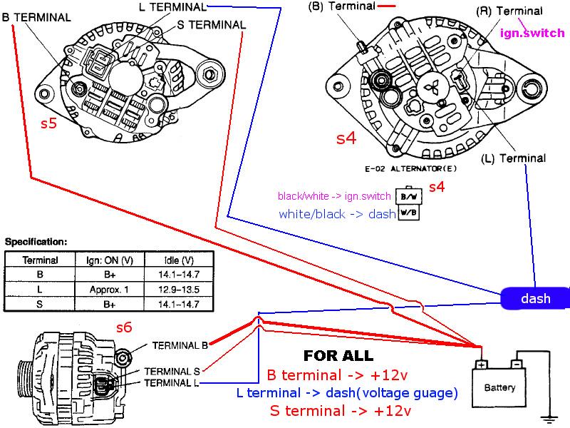
IF your car was a non turbo when built, then the white/black wire for the L terminal ran from the CPU into the front harness........crossed over to the passengers side where it mated with the EM harness.........traveled into the engine bay .........crossed over the engine behind the alternator/water pump, and ended up on the alternators electrical plug.
IF you removed the harness on the engine (the EM harness) and that EM harness exists no more..........that plug ain't thar no mo behind the alternator. But if the front harness part of what I described is still there, then if the ORANGE plugs still exists on the passengers foot well, then one of the two ORANGE plugss has that white/black alternator wire still in place. You could run a wire from that ORANGE plug to the alternators L terminal.
The diodes in my alternator are good. Its the damn regulator that's gone **** up. Not that hard to change out..............someday but not this day for sure. Gotta go screw my head back on before I lose it.
If your car was a turbo engine when built, then the above does not apply. ON a turbo engine the wire leaves the CPU on the front harness and then enters the engine bay on the drivers side of the car. It then mates with the true ENGINE harness and travels in the ENGINE harness to the area of the alternator and terminates in the alternator plug.
Or if the CPU is there, and you put the key to ON , engien OFF, and backprobe the White/Black wire on the CPU's upper plug, and find battery voltage there, you could cut that white/black wire a few inches from the CPU, and splice a new wire on it.
Then run the new wire into the engine bay on the drivers side of the car and run it to the alternators L terminal. It should read batt voltage with the wire off the alternator (key On, engien Off). Put the wire on the alternator and backprobe the wire with a meter and it should read 1-3vdc now, showing the regulator is good. If it reads something like 10vdc........its mucked up, and needs a new regulator.
I'd say....find the CPU. If it's there, write back. Don't write back if you don't have a meter and can't backprobe the WHITE/BLACK wire with the plug on the CPU. Can't work it without a meter.
If your horn works, the most likely it's still there. If your flashers work....it's there.
IF your car was a non turbo when built, then the white/black wire for the L terminal ran from the CPU into the front harness........crossed over to the passengers side where it mated with the EM harness.........traveled into the engine bay .........crossed over the engine behind the alternator/water pump, and ended up on the alternators electrical plug.
IF you removed the harness on the engine (the EM harness) and that EM harness exists no more..........that plug ain't thar no mo behind the alternator. But if the front harness part of what I described is still there, then if the ORANGE plugs still exists on the passengers foot well, then one of the two ORANGE plugss has that white/black alternator wire still in place. You could run a wire from that ORANGE plug to the alternators L terminal.
The diodes in my alternator are good. Its the damn regulator that's gone **** up. Not that hard to change out..............someday but not this day for sure. Gotta go screw my head back on before I lose it.
If your car was a turbo engine when built, then the above does not apply. ON a turbo engine the wire leaves the CPU on the front harness and then enters the engine bay on the drivers side of the car. It then mates with the true ENGINE harness and travels in the ENGINE harness to the area of the alternator and terminates in the alternator plug.
Or if the CPU is there, and you put the key to ON , engien OFF, and backprobe the White/Black wire on the CPU's upper plug, and find battery voltage there, you could cut that white/black wire a few inches from the CPU, and splice a new wire on it.
Then run the new wire into the engine bay on the drivers side of the car and run it to the alternators L terminal. It should read batt voltage with the wire off the alternator (key On, engien Off). Put the wire on the alternator and backprobe the wire with a meter and it should read 1-3vdc now, showing the regulator is good. If it reads something like 10vdc........its mucked up, and needs a new regulator.
I'd say....find the CPU. If it's there, write back. Don't write back if you don't have a meter and can't backprobe the WHITE/BLACK wire with the plug on the CPU. Can't work it without a meter.
HAILERS
Joined: May 2001
Posts: 20,563
Likes: 27
From: FORT WORTH, TEXAS,USA
You said the doors open light works and that seems to be on the same board as the alt relay. That's good.
The WHITE/BLACK wire should be in the upper plug. ON the top row of the upper plug. And as shown in the jpg, it's the fourth wire over from the left. Top row. Drag that dead *** CPU out of it's location but leave the connectors on it. That gives you room to put a piece of wire/paper clip/something up it backside and then put a meter on that paper clip and see if there is batt volgage there or not. I'm sure there is.
The WHITE/BLACK wire should be in the upper plug. ON the top row of the upper plug. And as shown in the jpg, it's the fourth wire over from the left. Top row. Drag that dead *** CPU out of it's location but leave the connectors on it. That gives you room to put a piece of wire/paper clip/something up it backside and then put a meter on that paper clip and see if there is batt volgage there or not. I'm sure there is.
Joined: Feb 2006
Posts: 2,897
Likes: 2
From: Renton/Bellevue/Seattle WA
Awesome, if it is required for my blinkers than I have it. I have a DMM, so I will let you know how things work out in a few hours.
Thanks for the very detailed information. I fear my regulator is botched. :/ Next you will need to do a writeup on how to change those.
Thanks for the very detailed information.
I fear my regulator is botched. :/ Next you will need to do a writeup on how to change those.
HAILERS
Joined: May 2001
Posts: 20,563
Likes: 27
From: FORT WORTH, TEXAS,USA
You take the alternator out of the car and put it on a bench. You unscew the four long bolts that hold it together. You take something like a cheap butane torch and lightly heat up the area where the bearing case is (see FSM, Engine Electrical seciton). Just hot enough where you won't touch it with your fingers.
Then look at the picture in the FSM and use a common screw driver to seperate the two large parts of the alternator. Persnonally I have to strike the two EARS with a hammer judiciously to seperate the two halves.
You need a soldering iron to do the rest. I had one that had a sharp tip on it. I just ground the tip flat with a Mikita grinder to give it more area. Hold the iron against the twp places the regulator is soldered in ...one at a time til the solder melts and you can lift up that area. Then do the other soldering place. Remove the regulator/brushes. Install the new regulator. Oh, I forgot the two screws that also hold the regulator/brushes in.
Once the new regulator is soldered in and screws reinstalled, you take the PIECE OF WIRE that comes with the new regulator. From the outter bearing side of the case, you insert that wire while at the same time you hold the two brushes down with your fingers. The wire will pass thru the hole in the two brushes. Doing that holds the two brushes down and out of the way of the rotor when you put the two haves back together. Once the two halves have been bolted together with the four long bolts, you can now pull the wire out and put it on the shelf.
Actually the ENGINE ELECTRICAL seciton has a good how to in it on replacing the regulator/brushes. I didn't follow everything they say to the letter. I wrote from memory.
HAILERS
Joined: May 2001
Posts: 20,563
Likes: 27
From: FORT WORTH, TEXAS,USA
See the last or third jpg I attached in my last post. AutoZone I think. You HAVE to get the right regulator. You cannot put a non turbo regulator in a turbo alternator and vice versa. It's a physical requirement. One regulator jack exits the side of the case. The other exits the aft side/end of the case.
Joined: Feb 2006
Posts: 2,897
Likes: 2
From: Renton/Bellevue/Seattle WA
See the last or third jpg I attached in my last post. AutoZone I think. You HAVE to get the right regulator. You cannot put a non turbo regulator in a turbo alternator and vice versa. It's a physical requirement. One regulator jack exits the side of the case. The other exits the aft side/end of the case.
HAILERS
Joined: May 2001
Posts: 20,563
Likes: 27
From: FORT WORTH, TEXAS,USA
On a series five, if you walk up to a non turbo alternator, the electrical jack faces straight up out the side of the alt case. If you walk up to a TURBO alternator, the electrical jack is facing aft.
The last time I got a regulator, I knew it was a series five and the jack faced upwards. That made it a non turbo alternator I was using on a turbo engine. So I got lucky because it cost less than the turbo regulator.
The alternator I messed up today is a Turbo alternator because the electrical jack faces aft. In other words it can only be seen if looking at the aft side of the alternator. Duh. That sucker cost a bit more. Helps to have a spare alternator. Won't get fixed for a while. No need to. Even then, it works to some extent as is, so it's still good as a spare.
The last alt reg I replaced had the same symptoms. No 1-3 vdc on the L wire when key ON, engine OFF. Shows 10vdc instead. Replaced that regulator and now on THAT alternator I have the regulated 1-3vdc , key ON, engine off on the L wire.
Joined: Feb 2006
Posts: 2,897
Likes: 2
From: Renton/Bellevue/Seattle WA
Ok. Well, I got a lot of work ahead of me. I feel that this thread is going to help a LOT of people. I bet 1/2 the people on here have blown regulators, or does't know where to get the source for their L wire.
Thanks from everyone that gets amazing help from this thread.
Thanks from everyone that gets amazing help from this thread.
Full Member
Joined: Apr 2005
Posts: 167
Likes: 0
From: Sydney Australia
Well actually... you can use it and just fine, but it is beyond most people here so I don't show how anymore. As long as the internal diode has not failed- but it seems more and more people just don't get that the wiring is different between the series and install the alt wrong (despite the FAQ for FC and countless threads on this in the archive)
Yep, given the vast amount of info on this, I still do not understand how people can wire the alt up wrong, so you have to assume that the alt is a crappy alt too.
There actually is a Diode inside most alts for this wire. This is a little three or 6 amp diode/rectifier that will smoke if you run too many amps through it. This is the one that is most commonly blown out when the alt is installed wrong.
So a 15 or 30 amp fuse on a circuit that dies with 4 amps is radically overkill. But if you mis-run the wire and it rubs through to a ground, a 18 awg or 20 awg wire will melt long before the fuse blows. So the fuse is not protecting the alt- it is protecting the wire.
Yes, I was an auto electrician for 17 years myself, and I was the one that posted up how to fix this 5 or 6 years ago on this board and Team somthing or the other.
So it is again beyond me, with how many diagrams and threads on this in the archives here and other boards and even in the FAQ for FC here that people can still get this wrong.
And I am merely saying that the fusing and wiring you are suggesting is overkill and probably not protecting the wiring. Remember fuses are to protect the wiring not the component. It is up to the component designer to include protection from voltage spikes (both directions) and the internal workings (which they do 99% of the time).
BTW: It is commonly accepted that a less than 15 ft wire run with fine stranded wire (such as used for most automotive stereo installations) that a 12/15 volt single phase is running through that a 8 awg wire is capable of handling 150 amps through it, so by your diagram using two 8 awg wires, you are maxing the capability to 300 amps... far more than any conventional alternator will ever allow.
Now if you are using thick strand that drops considerably, and if you are using solid core that drops down to only 73 amp (based on the National Electrical Code, the maximum Amps for Power Transmission uses the 700 circular mils per amp rule, which is very very conservative).
Yeh unfortunately giving advice to people that aren�t auto elecs will have its pitfalls cause of human nature.
Ie to lazy to do it right or misreading the instructions and rather than find the mistake they would rather ask on the net why its not working than fix the problem at hand, even though the problem is looking them in the face.
Yeh love how the alternator is **** when it�s the users fault for stuffing it by not following directions properly.. lol
Basically its like this for my diagram. Which is why I have developed it the way I have and why when I do this, I�ve never had an issue with an install related to wiring.
I know the fuse protects the cable at all times, but I did a few things to help the system be more reliable..
B+ wire -
If you look at an FC series 4 that has a factory wiring it has a single 8 gauge wire. Everyone you see is has the insulation burnt at the alternator, sometimes a good inch and a half down the cable I�ve seen, which is why I say upgrade the B+ cable...
So by running a Dual 8 gauge B&S cable it is rated at 200 amps in total (this allows for any future upgrade if a bigger alt is ever needed too, you just change the circuit breaker capacity and its done).
But cause the alt is rated at 100 amps that�s why I put the 100A circuit breaker at that size so it the alt is stretched beyond its capacity the circuit breaker will trip and let you know there is a problem. Rather than keep stretching the regulator out and blow it.
Then you know there is a problem reset the circuit breaker and you can atleast get the car home and then sort the issue.
L wire �
From factory this wire carries a 30 amp fuse and thought this to be excessive.
But to truly know you would have to test the wire when the electrical system is at full load. Ie everything on possible plus the car at full acceleration to get a �true� load requirement on this wire. Measuring it at idle is no indication of its true peak load IMO
I have found in the past that if there is more than 1 volt difference between the L and B+ wires the alt will go into a �limp� mode and the alternator will sit on a constant 16 volts.
By running the L terminal cable off the same source the B+ ie both connection at the battery(or at the starter motor battery supply terminal for a battery in the boot install) this greatly reduces the 1 volt difference between the terminals and makes for a happy alt
So I used a 4mm wire with is rated at 15 amps and used a 15 amp fuse.
S wire �
This is done for shear simplicity. The charge wire is already there, so use the factory one instead of adding a whole new charge circuit and making the install more complicated. Plus if this terminal doesn�t have this input the voltage on the B+ will �float� from 12-16volts at any given time.
By connecting this wire correctly the voltage stays completely stable at around the 14.1 volt mark.
Hope this explains my system, thought process and developement and clears any issues..
cheers
HAILERS
Joined: May 2001
Posts: 20,563
Likes: 27
From: FORT WORTH, TEXAS,USA
The first three jpg are from a man explaining how alternator/regulators work (Delco). The third jpg is the picture he had with his article.
The fourth jpg is out of our FSM. It is not exactly the same as his, but functions the same. The L voltage enters the alternator....passes thru the field (rotor) ....goes to the regulator where it passes thru a transistor and then goes to gnd. That's the excitation voltage. When the voltage is up to par, that transistor is *shut off* and the alternator isn't charging anymore. It flip flops like that quite a bit evidently.
The last jpg is the actual regulator without the brush assy. About a inch X inch and waffer thin. It can be changed out all by itself and bought seperatley from the whole brush assy........I think. About to find out if that's true.
Not too many weeks ago I thought the L was only for the activation of the warning light. Ain't so. Sim RX3 kinda got me to rethinking (heck, didn't know in the first place) how stuff works.
NOTE: In the article above he talks about terminal one and terminal two. Terminal one is the warning light and terminal two is the wire sensing batt voltage. His jpg was sooooooooo small, and I made it bigger but it's foggy.
I've no arguments with any of the posts above. I just searched on the net last night and found the article above.
Former Moderator. RIP Icemark.
Joined: Apr 2001
Posts: 25,896
Likes: 24
From: Rohnert Park CA
Not too many weeks ago I thought the L was only for the activation of the warning light. Ain't so. Sim RX3 kinda got me to rethinking (heck, didn't know in the first place) how stuff works.
NOTE: In the article above he talks about terminal one and terminal two. Terminal one is the warning light and terminal two is the wire sensing batt voltage. His jpg was sooooooooo small, and I made it bigger but it's foggy.
I've no arguments with any of the posts above. I just searched on the net last night and found the article above.
But based on this diagram, the field will also establish from the R lead, just at a reduced voltage, as you can see the R lead also travels through a feed diode, it just adds a resistor in the regulator and then feeds direct onto the L terminal and leads.
In essence the L and R are joined together in the regulator, but only the L lead can have a ground supplied too it by the staggered transistors in the regulator.
And did you note, that in the first and second attachments, that it says, "the L circuit can not supply enough current to sustain or generate a magnetic field in order to induce a voltage from the Stator windings"
Again... based on that diagram, the field would establish just fine without the L lead even being hooked up.
I also got a similar problem but its on my S4 alt, when my car is still has an cold engine it got 14.0 volts but when the engine is warmed up volts go down to 13.5V then go down to 11.8 and sometimes goes back to 13.5V but keeps on coming back to 11.8V with lights off and accessories off and the idiot cluster lights turns on when it has low voltage.
I took the alt for a test and they said its fine. Could it be the alt is failing already?
I took the alt for a test and they said its fine. Could it be the alt is failing already?
HAILERS
Joined: May 2001
Posts: 20,563
Likes: 27
From: FORT WORTH, TEXAS,USA
I also got a similar problem but its on my S4 alt, when my car is still has an cold engine it got 14.0 volts but when the engine is warmed up volts go down to 13.5V then go down to 11.8 and sometimes goes back to 13.5V but keeps on coming back to 11.8V with lights off and accessories off and the idiot cluster lights turns on when it has low voltage.
I took the alt for a test and they said its fine. Could it be the alt is failing already?
I took the alt for a test and they said its fine. Could it be the alt is failing already?
I'm a big believer in reading the alternator output AT the alternator itself with a meter. Positive lead on the large output terminal and the negative ON the alternators CASE.
So the next time you see the flopping around, put a meter on the alternator as described above and see what the meter reads.
There's a fair chance that even that 14vdc you read when cold (whether you read it at the battery or the car gauge) is really in the mid/high 14vdc at the alternator. The reason for the difference would be voltage drops from the alternator B termianl to the engine bay fuse box and or bad grounding b/t the alternator case to the negative terminal on the battery.
And or it could be the alternator is getting old and the carbon brushes in the alt are wearing down to a nub. Who knows. Do the voltage check above.
HAILERS
Joined: May 2001
Posts: 20,563
Likes: 27
From: FORT WORTH, TEXAS,USA
What causes a thread to suddenly get so wide on the computer screen? So large that you can't read a quarter of the page without tabbing right to left and back and forth all the time. It's a pain in the ***.
HAILERS
Joined: May 2001
Posts: 20,563
Likes: 27
From: FORT WORTH, TEXAS,USA
I also got a similar problem but its on my S4 alt, when my car is still has an cold engine it got 14.0 volts but when the engine is warmed up volts go down to 13.5V then go down to 11.8 and sometimes goes back to 13.5V but keeps on coming back to 11.8V with lights off and accessories off and the idiot cluster lights turns on when it has low voltage.
I took the alt for a test and they said its fine. Could it be the alt is failing already?
I took the alt for a test and they said its fine. Could it be the alt is failing already?
I assumed you made sure your belt was tensioned right. Maybe I shouldn't assume things.
Parastic loss?
After the FD alt install I've had problems with my battery draining overnight.
I used a multimeter to check the amps through the negative battery terminal and the negative clamp.
I tested the amps with the car off, I was getting like 0.2 amps with the car off.
After removing wire on the L terminal I get like .02...? Is the alt regulator shot?
I wired as below.
I used a multimeter to check the amps through the negative battery terminal and the negative clamp.
I tested the amps with the car off, I was getting like 0.2 amps with the car off.
After removing wire on the L terminal I get like .02...? Is the alt regulator shot?
I wired as below.
Yes belt was tensioned right, Now when its warmed the voltage is always down below 12V not going up to 13.5 or normal voltage, and when i step on the brakes all the idiot clusters lights turned on
HAILERS
Joined: May 2001
Posts: 20,563
Likes: 27
From: FORT WORTH, TEXAS,USA
Yours is a series four alternator and it sounds like it's toast. It's probably just the brushes in the alternator that are bad. Unfortunatly you' have to buy the regulator with the brushes to fix it. And you have to solder it in the old alternator so it depends on skills/tools etc.
The brush/regualator assy cost about 45 bucks non turbo (about 80 bucks turbo alternator). But I've found a place on EBAY that sells cheaper and I ordered one for a Turbo alternator (series five) for 27 buck total including shipping. Whether or not this is a good deal won't be found out til it gets here next week.
There is a way to tell if the diodes are good bad, but you need a meter etc to find out. Can be done with the alternator on the car.