
Electric Air pump diagram for aux ports and VDI - Someone check this.


Thread Starter
Joined: Mar 2007
Posts: 1,029
Likes: 0
From: Appleton, WI
Electric Air pump diagram for aux ports and VDI - Someone check this.
yay MSpaint
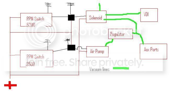
Here's how it works.
3500 RPM activates the first RPM switch and grounds the relay, which turns on the air pump. This opens the aux ports.
5200 RPM activates the second RPM switch and grounds that relay, which opens the solenoid and activates the VDI.
The air regulator is made for airbrushes. here's one very close to the one I got.
http://cgi.ebay.com/Airbrush-Compres...QQcmdZViewItem
The regulator will be set to 5 or 6PSI, whatever is just enough to open both the VDI and 6 ports. The high-pressure side of the regulator should ensure that the pressure doesn't drop on the low pressure side and close the 6 ports when the VDI opens.
Looking for some feedback and comments. Do you think it will work? How can I improve it?
I already have two summit RPM switches, a bicycle 12v air pump, the regulator, and plenty of 5/32" vacuum line and tees.

Senior Member
Joined: Jul 2007
Posts: 308
Likes: 0
From: North Dakota


Joined: Dec 2003
Posts: 6,598
Likes: 10
From: Temple, Texas (Central)
Or this one: http://howto.globalvicinity.com/gv_w...i=48&co=1&vi=1
I actually wrote that one.
As for your digram, it looks like it will work pretty well. Go for it.
I actually wrote that one.
As for your digram, it looks like it will work pretty well. Go for it.
Thread Starter
Joined: Mar 2007
Posts: 1,029
Likes: 0
From: Appleton, WI
Thanks for the responses. I suppose I'll give it a shot.
I've actually seen both of those links before, but like I said, I already have all of the parts necessary for this setup. The reason I'm asking instead of just following one of the several walk throughs out there is because I am running VDI and Aux ports off of the same air pump, and all of the other walkthroughs only do one or the other.
I've actually seen both of those links before, but like I said, I already have all of the parts necessary for this setup. The reason I'm asking instead of just following one of the several walk throughs out there is because I am running VDI and Aux ports off of the same air pump, and all of the other walkthroughs only do one or the other.

Thread Starter
Joined: Mar 2007
Posts: 1,029
Likes: 0
From: Appleton, WI
Can anyone give me a reason this won't work before I try it today?
I'll be adding a switch to disable the entire system...City driving usually puts me in the 3k range and I would hate to have the airpump constantly turning on and off without actually getting used...
I'll be adding a switch to disable the entire system...City driving usually puts me in the 3k range and I would hate to have the airpump constantly turning on and off without actually getting used...
Trending Topics
Sorry to bring back this thread but did this actually work for you?

This is not my diagram, but someone made this very helpful diagram. Since you are S4 and looking to go S5 and don't have the ECU, you can replace the applicable ECU pinout with an RPM switch and rig everything up like this.


Thread
Thread Starter
Forum
Replies
Last Post
sherff
Adaptronic Engine Mgmt - AUS
9
Feb 24, 2019 12:09 PM
12abridgeport
1st Generation Specific (1979-1985)
2
Aug 17, 2015 06:28 PM