
DIY cold air box

Thread Starter
Joined: Mar 2008
Posts: 8,718
Likes: 6
From: San Diego, CA
DIY cold air box
So, I just finished building my air box to use with a custom TID. I made it from a piece of 1/16" 5052 polished aluminum sheet, and bent the entire thing to shape. Then I went ahead and made a lid for it, to both block off the rest of the engine bay, and give it a cleaner look. It pulls air from behind the headlight & up near the coolant reservoir. I used some foam w/ tape backing to seal up the gaps and block off anywhere that hot air cold get sucked in (not all shown in the pictures).
The hoodprop had to be able to clear the edge of the lid, otherwise I'd have made the metal follow the body lines a little better.
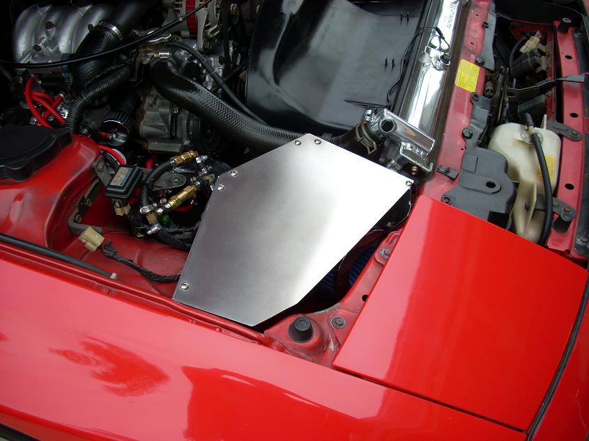
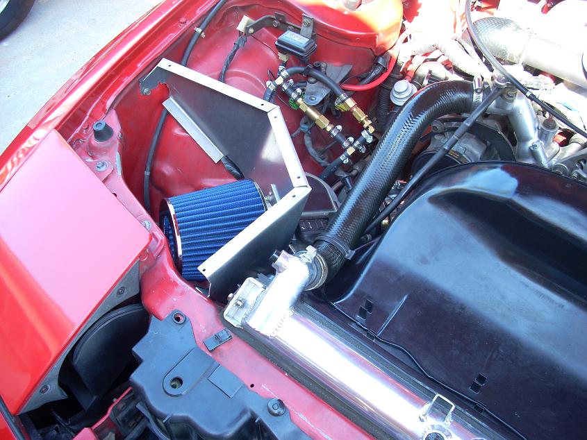
I had a cheapo eBay filter in there for the pictures, but have replaced it with an AEM dryflow, which actually has test data to show how well it filters.
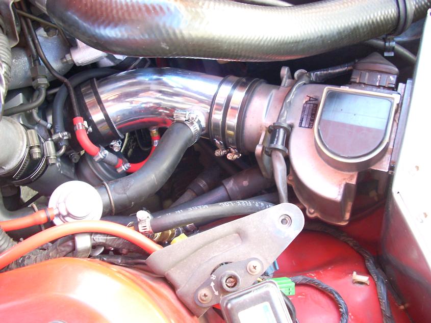
The TID pipe itself was made from a generic 45*, 3" pipe (eBay ricer special). I cut it to length & added in connections for the PCV system and the stock BOV. I can actually hear the BOV make a "pshhh" noise whenever I let off now. With the stock intake, it was so quiet, I almost never heard it vent. Intake suction noise / turbo spooling noise is also increased. Again, a lot louder than stock.
The turbo spools faster and hold boost much better than before too. I'm actually making 10 psi in 1st gear, and a solid 11 psi in 2nd, 3rd, 4th, 5th (I have my MBC set for 11 psi max). With the stock intake, pressure would drop off dramatically towards redline, but now I'm able to hold a lot more pressure all the way up. So far, I've seen 9-10psi up to at least 6000 rpm in 3rd gear, which is amazing for the stocker. Most people have trouble making anything more than 6-7psi up to redline, so I'm still scratching my head a bit on this one. But I'm not complaining! The powerband no longer has that pronounced dip in torque as I pass the 5k mark. It's much less now, and makes mashing the throttle even more fun than before.
I've got all the measurements for the air box, and plan on making up a drawing for anyone that might want to make one (or a similar one). It's best if you have a good set of sheet metal tools/equipment such as a shear, band saw, brake, etc...but you could still do it with a hacksaw, a vice & some files. It'll just take a lot longer . I probably put a good 40 hours into this thing, but most of that was spent trying to get the shape just right.
The hoodprop had to be able to clear the edge of the lid, otherwise I'd have made the metal follow the body lines a little better.
I had a cheapo eBay filter in there for the pictures, but have replaced it with an AEM dryflow, which actually has test data to show how well it filters.
The TID pipe itself was made from a generic 45*, 3" pipe (eBay ricer special). I cut it to length & added in connections for the PCV system and the stock BOV. I can actually hear the BOV make a "pshhh" noise whenever I let off now. With the stock intake, it was so quiet, I almost never heard it vent. Intake suction noise / turbo spooling noise is also increased. Again, a lot louder than stock.
The turbo spools faster and hold boost much better than before too. I'm actually making 10 psi in 1st gear, and a solid 11 psi in 2nd, 3rd, 4th, 5th (I have my MBC set for 11 psi max). With the stock intake, pressure would drop off dramatically towards redline, but now I'm able to hold a lot more pressure all the way up. So far, I've seen 9-10psi up to at least 6000 rpm in 3rd gear, which is amazing for the stocker. Most people have trouble making anything more than 6-7psi up to redline, so I'm still scratching my head a bit on this one. But I'm not complaining! The powerband no longer has that pronounced dip in torque as I pass the 5k mark. It's much less now, and makes mashing the throttle even more fun than before.
I've got all the measurements for the air box, and plan on making up a drawing for anyone that might want to make one (or a similar one). It's best if you have a good set of sheet metal tools/equipment such as a shear, band saw, brake, etc...but you could still do it with a hacksaw, a vice & some files. It'll just take a lot longer
. I probably put a good 40 hours into this thing, but most of that was spent trying to get the shape just right.
Last edited by RotaryRocket88; Dec 14, 2011 at 06:42 PM. Reason: Attached photos since the links were dead


Joined: Dec 2006
Posts: 2,859
Likes: 13
From: Sterling Heights, MI
Nice! That's some high quality work right there. In fact, your whole engine bay looks like that of a brand new car. Mad props 
What's all those hoses and fittings up behind the airbox?
What's all those hoses and fittings up behind the airbox?
Thread Starter
Joined: Mar 2008
Posts: 8,718
Likes: 6
From: San Diego, CA
I knew someone would ask right away about those hoses, haha. That's my overkill MBC. Consists of a ball-n-spring relief valve and a brass check valve to vent pressure from inside the lines once the wastgate closes. I know, it's ugly right now. I'm actually going to make a little enclosure for it that mounts near the boost sensor.
I've got some other projects to un-clutter the engine bay a little too. The air pump is coming off, and I'll be making a custom idler pulley to replace it. No need for a double alternator pulley or yoohoo belt if I do it that way. The stock fan is probably coming out too. I already have an e-fan with some nice mounts left over from my TII.
Thread Starter
Joined: Mar 2008
Posts: 8,718
Likes: 6
From: San Diego, CA
im thinking about doing something in the likes of hiding all this under a stock airbox, and than cutting out the bottom portion of the bay and doing a duct that runs from the front of the car to that area, alla stealth mode, since us guys in Cali shouldnt be rocking any trick parts since we would face criminal charges if a cop ever pulls us over hahahah
Trending Topics
Thread Starter
Joined: Mar 2008
Posts: 8,718
Likes: 6
From: San Diego, CA
im thinking about doing something in the likes of hiding all this under a stock airbox, and than cutting out the bottom portion of the bay and doing a duct that runs from the front of the car to that area, alla stealth mode, since us guys in Cali shouldnt be rocking any trick parts since we would face criminal charges if a cop ever pulls us over hahahah
And I originally intended to paint it black and try to make it stock-ish, but decided it looked too nice polished up
Thread Starter
Joined: Mar 2008
Posts: 8,718
Likes: 6
From: San Diego, CA
And to cut it all out, I used a sheet metal shear for the most part to give nice, clean cuts. Anything I cut with the band-saw or hack-saw I cleaned up with files. I have access to all sorts of equipment left over from my family's welding / fabrication business, so I luck out in that department.
Thread Starter
Joined: Mar 2008
Posts: 8,718
Likes: 6
From: San Diego, CA
It's just as easy to use the S5 AFM. You can make the hole through the box larger, and surround it with foam. That way it doesn't have to actually attach to it, but it can rest securely. It would actually give the intake setup a little more flexibility when the engine moves around.

Thread Starter
Joined: Mar 2008
Posts: 8,718
Likes: 6
From: San Diego, CA
Air comes from behind the headlight & from the stock location forward of the radiator. I adjusted the weather stripping on the hood to allow air through the side. It's really up to you though. I know a lot of people prefer to drill a big hole in the bottom to pull up from below.
Great job it looks something like mine. Did you relocate your washer tank? I used insulation board on the back panel of mine and also added a cold air intake hose, you can see it below the filter in this picture. In the next picture you can see the other end of the hose above the passenger side fog light. A lot of air comes through the intake hose the dirt really collects on the filter in that spot. Me and my son tested it with a leaf blower standing back from the car. I put my hand in there and the air really comes in. Since this picture I've made a new afm bracket and realigned it to lay flat like the stock position.
Thread Starter
Joined: Mar 2008
Posts: 8,718
Likes: 6
From: San Diego, CA
Great job it looks something like mine. Did you relocate your washer tank? I used insulation board on the back panel of mine and also added a cold air intake hose, you can see it below the filter in this picture. In the next picture you can see the other end of the hose above the passenger side fog light. A lot of air comes through the intake hose the dirt really collects on the filter in that spot. Me and my son tested it with a leaf blower standing back from the car. I put my hand in there and the air really comes in. Since this picture I've made a new afm bracket and realigned it to lay flat like the stock position.
I plan on insulating the back wall of it with some stick on heat-resistant mat, and I'll probably remove the washer bottle to get some extra airflow. It's definitely not starving for air right now, but the more the better.
you probably dont need to go all out, you do have an intercooler after all. no mater what, the air passes thru a hot turbo first , so a cold air wont really do much imo. it all comes down to the IC
I like Davidp's job with the ducting, helps feed some air into it.
I like Davidp's job with the ducting, helps feed some air into it.
Thread Starter
Joined: Mar 2008
Posts: 8,718
Likes: 6
From: San Diego, CA
Drawings
So, here they are finally. It actually took me a long time to get these right. It's been years since I used AutoCAD, so I had to relearn it, haha. Sorry about the widescreen format. I run 1600 x 1000 resolution.
All measurements are in inches. And I didn't note the width of all the tabs in the drawing, but they're 0.75". It'd get too cluttered with them in there too. Also, if you have A/C in your car, you'll need to bend the hardline that runs to the condenser in order to fit the box in. And a 5" filter will fit just barely, as long as the connector section is about 1" or less. If more room is needed, you can move the AFM attachment point closer to the passenger-side of the car.
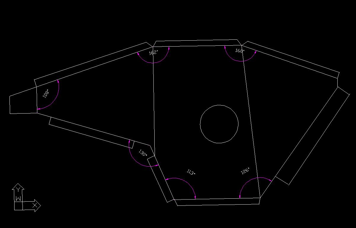
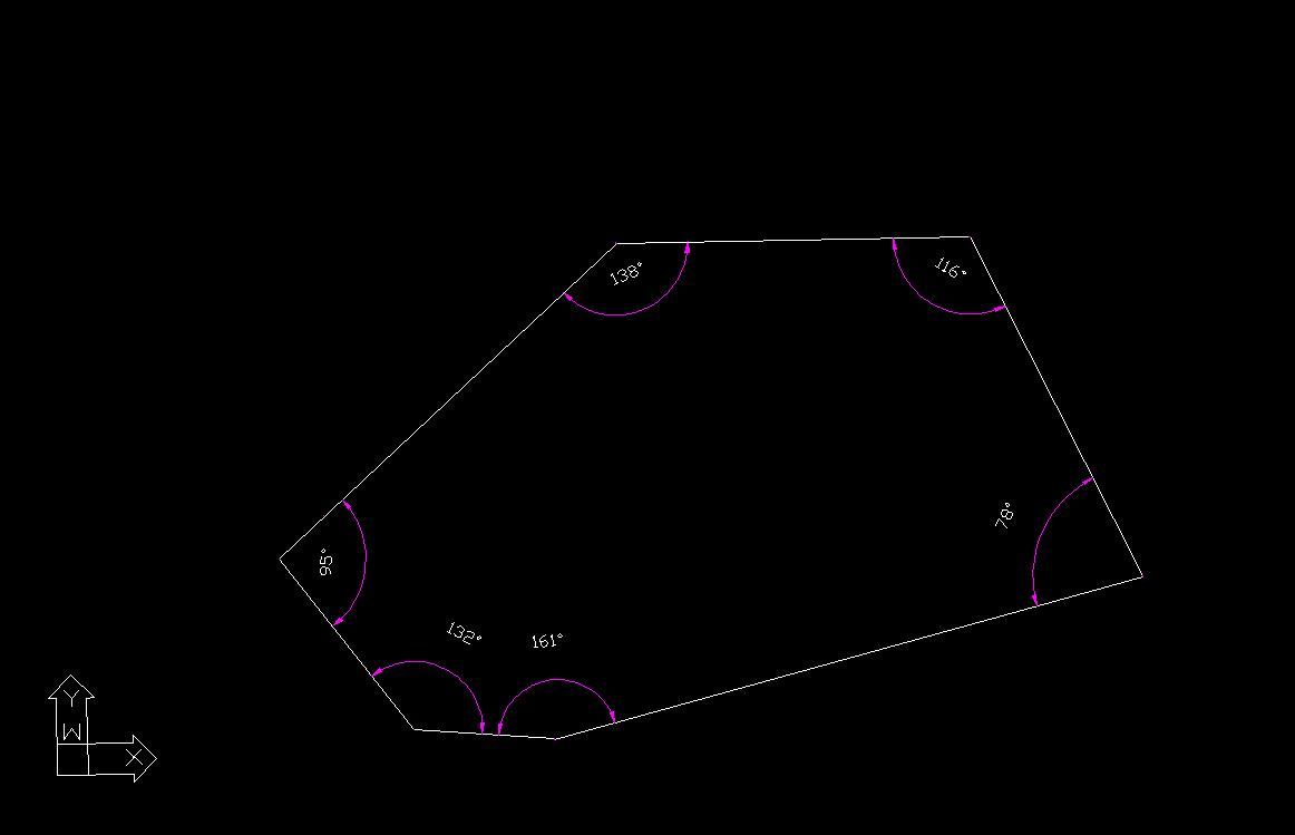
All measurements are in inches. And I didn't note the width of all the tabs in the drawing, but they're 0.75". It'd get too cluttered with them in there too. Also, if you have A/C in your car, you'll need to bend the hardline that runs to the condenser in order to fit the box in. And a 5" filter will fit just barely, as long as the connector section is about 1" or less. If more room is needed, you can move the AFM attachment point closer to the passenger-side of the car.
Last edited by RotaryRocket88; Dec 14, 2011 at 06:46 PM. Reason: dead links
Joined: Feb 2001
Posts: 29,798
Likes: 128
From: London, Ontario, Canada
That's probably one of the nicest airboxes I have seen on this forum.
Now, about this...
Remember that the compressor is heating the air charge coming into the compressor not to a specific temperature, but a specific amount. Thus if the air charge is at 10 degrees (random number) and the compressor adds 50 degrees, you have 60 degrees heading into the intercooler. If the intake temps at the compressor are at 0 degrees then you are only seeing 50 degrees into the intercooler.
A lower temp into the intercooler means it has to reject less heat and will ultimately lead to lower intake temps at the engine.
Now, about this...
A lower temp into the intercooler means it has to reject less heat and will ultimately lead to lower intake temps at the engine.
Thread Starter
Joined: Mar 2008
Posts: 8,718
Likes: 6
From: San Diego, CA
That's probably one of the nicest airboxes I have seen on this forum.
Now, about this...
Remember that the compressor is heating the air charge coming into the compressor not to a specific temperature, but a specific amount. Thus if the air charge is at 10 degrees (random number) and the compressor adds 50 degrees, you have 60 degrees heading into the intercooler. If the intake temps at the compressor are at 0 degrees then you are only seeing 50 degrees into the intercooler.
A lower temp into the intercooler means it has to reject less heat and will ultimately lead to lower intake temps at the engine.
Now, about this...
Remember that the compressor is heating the air charge coming into the compressor not to a specific temperature, but a specific amount. Thus if the air charge is at 10 degrees (random number) and the compressor adds 50 degrees, you have 60 degrees heading into the intercooler. If the intake temps at the compressor are at 0 degrees then you are only seeing 50 degrees into the intercooler.
A lower temp into the intercooler means it has to reject less heat and will ultimately lead to lower intake temps at the engine.
And that's exactly why intake temps are so important. They're the only variable we can control easily, as the efficiencies of the turbo and intercooler are set.
I've done some calculations on this, and without posting all the thermodynamics details, here's what it comes down to:
Assume we have a turbo with 72% efficiency, operating at 10 psi, with an intercooler that is 68% efficient (stock TMIC). If the intake is pulling in 70 F air, then it is 185 F exiting the compressor and finally 107 F entering the engine. Now if intake air is increased to 80 F, it jumps to 198 F from the compressor and 111 F entering the engine.
So a 10 degree increase in intake temps resulted in a 4 degree increase in what's going into the throttle body. I'd say that's pretty significant since radiator air can easily be 40, 50+... degrees hotter than ambient temps.