
Can BAC compensate for efan?

Thread Starter
~~~~~~~~~~~~~~~~~~~~~~~
Joined: May 2001
Posts: 1,594
Likes: 0
From: Pittsburgh, PA
Can BAC compensate for efan?
I have read that you can access an unused ECU input (PS or AC) to let the BAC know that your efan has just turned on. Anyone know how this can be done?


Thread Starter
~~~~~~~~~~~~~~~~~~~~~~~
Joined: May 2001
Posts: 1,594
Likes: 0
From: Pittsburgh, PA
Thank you for the picture.
I am thinking I would need to run a wire from the efan relay to the ECU AC input pin. This wire will get 12v when the fan is on. I would just need to figure out which pin on the ECU is for the AC input.
I am thinking I would need to run a wire from the efan relay to the ECU AC input pin. This wire will get 12v when the fan is on. I would just need to figure out which pin on the ECU is for the AC input.
Please post your findings...I'm interested in the exact same thing.
Joined: Apr 2005
Posts: 3,785
Likes: 30
From: And the horse he rode in on...
If you want additional help on top of the a/C, you will need to piggy the fan onto another input. The least used input on my car is the Rear defroster.

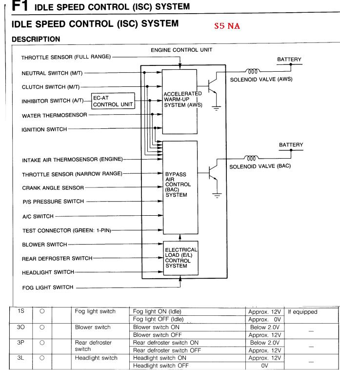
I'm not positive that the ECU would actually need to see +12V on s5 n/a pin 1O with the A/C off. But if you wanted to recreate the exact behavior the ECU expects,, here is how you would do it using a 5 pin relay:
Most people have never used the "87a" terminal of a 5 pin relay. The 87a terminal is what's called an "NC" or normally closed contact. So when you are talking about wiring (in vacuum routing it is different), the term "normally closed" means that there will be continuity between that pin and the pin it is connected to on the relay, in this case the relay output pin 30. When the switch (the coil in the relay) is engaged, pin 87a will no longer have continuity with the relay pin 30, and there will now be continuity between relay pin 30 and relay pin 87 like most people expect from a relay. So if we hook up +12V (ignition switched +12V would be best) to pin 87a, S5 n/a ECU pin 1O ("O" as in owl) will see +12V under normal conditions.
Pin 87 on the the relay, a pin many of us are familiar with, is what's called a "normally open" NO pin. When you are in the realm of wiring, normally open means that there is no continuity with the pin it is connected to (relay pin 30) unless the coil is engaged. In your case, the coil will be engaged by whatever you are using to trigger your e-fan relay.
The coil is essentially a tiny magnet that is active when the circuit between the two terminals is complete. The two terminals for the coil in the relay are pins 85 and 86. One of those must see ground and one of those must see +12V to engage the coil. Engaging the coil means that whatever was connected to relay pin 87a will no longer go out relay pin 30. Now whatever is connected to relay pin 87 will go out pin 30. For example, if your e-fan relay is triggered by a ground of some sort, tap a wire from that trigger into relay pin 85. Then hook pin 86 into either constant +12V or ignition powered +12V. Now your hookup is complete.
To review:
According to the FSM, pin 1O, the A/C input pin that could be used to idle the car up, should see +12V with the e-fan fan off and GND with the e-fan on. Since pin 87a of our relay will normally be connected to the output of the relay, we hook that to +12V so the ECU gets the signal it's expecting on a factory car with the A/C disengaged. The ECU then expects ground to trigger the idle up function, so we hook pin 87 to ground. To engage pin 87, we hook pin 85 to our fan relay trigger, and pin 86 to whatever is the opposite polarity of our fan trigger.
pin 87a -- normally closed, will be switched off by the coil
pin 87 -- normally open, will be switched on by the coil
Note that on s5 models A/C input is pin 1O ("o" as in owl) while on s4 models A/C input is pin 1E. The same basic approach could be used with a different input pin on a given ECU (P/S input for example), you just need to look through the pinout and see what the ECU expects then alter your wiring accordingly.
Trending Topics
Thread Starter
~~~~~~~~~~~~~~~~~~~~~~~
Joined: May 2001
Posts: 1,594
Likes: 0
From: Pittsburgh, PA
thank you arghx! How could I determine which type of trigger I have? I am using one of those thermo sensors that attach to the radiator to trigger the efan relay, it has an adjustable temperature dial. I am not sure if this is a ground or 12v trigger.
uh read the instructions? or scan them and post them if you can't figure it out? or you could just tap the output pin from your fan relay. So if your fan relay is sending +12v to the fan out pin 30, you could splice a wire into that big power wire and use it to trigger the +12V side of the coil on your your idle-up relay. There are a ton of ways to do this depending on how you have the circuit set up.
Last edited by arghx; Jun 30, 2009 at 09:33 PM. Reason: output of fan relay
Thread Starter
~~~~~~~~~~~~~~~~~~~~~~~
Joined: May 2001
Posts: 1,594
Likes: 0
From: Pittsburgh, PA
Looks like the fog light switch would be easier since the ecu sees 12v when it is on. So I could just trigger that with the same pin that powers the efan. although I am not sure the ecu will throttle up the idle as much for the fog lights as it would for the ac. The compensation from the ecu for the fog lights might not be enough for the drain of the efan. any thoughts?
Joined: Apr 2005
Posts: 3,785
Likes: 30
From: And the horse he rode in on...
Looks like the fog light switch would be easier since the ecu sees 12v when it is on. So I could just trigger that with the same pin that powers the efan. although I am not sure the ecu will throttle up the idle as much for the fog lights as it would for the ac. The compensation from the ecu for the fog lights might not be enough for the drain of the efan. any thoughts?
Why not try to find one of the factory inputs that draw similar amounts of current that your efan draws?
OK, since I'm hip deep in another project (writeup to come soon), I'm counting on you guys to make my life easier on this one.
I understand the theory and application thereof of this mod, now the question is exactly how to execute it.
Having already deleted both the AC and PS it seems logical to assume that one of the now unused connectors has a wire that leads to the ECU for the BAC activation signal ("Pin IO...o as in octopus"!!??).
This may not be true but I'm hoping it is since it would save having to run a wire into the cabin and splicing into the ECU harness.
Anyone want to do my legwork for me?
you need to find the connector for the A/C refrigerant pressure switch I think. when you press the A/C button, the ground goes to that switch first, and if the refrigerent pressure is too low (A/C has a leak etc) then the ECU never sees the ground. so maybe you could hook it up on the output of that switch. Or figure out which connector on the front harness you could splice it into. I think the ECU gets the signal on the big plug, the one that connects to the front harness and not the fuel injection ("emissions") harness. you're going to have to figure the rest out yourself, I've done plenty of work for you. Download the wiring diagram section of the FSM. Read through the opening pages very carefully as they explain what all the symbols mean.
and when I said pin "1O" i meant that it is the number one and letter "o" . 1 is the connector designation, and "o" is the pin designation. That pin only applies to s5 models. On s4 models it is pin 1E.
The fog light input would work too (on the s5) but I agree that it may not idle up as much as you would prefer. The A/C is the biggest drag on the engine and will get the most idle compensation.
So, you connected the plug/wire that usually runs to the A/C pressure switch to a switched ground source for the fan? Meaning whenever the fan is grounded, the ECU pin is grounded, as well?
Just finished wiring mine up...here's how I did it.
Depending on your thermoswitch (fan trigger) is set up, you may have to alter this a bit.
My thermoswitch- a two stage Audi/VW unit- grounds the low, then the high speed triggers for the Taurus fan. I was fortunate that this switch has a separate ground wire (it DOES NOT ground through the switch body) and that made this install quite simple.
This ground wire from the thermoswitch went to pin 85 on a Bosch relay (you don't need a 5 pin relay as was previously suggested). Pin 86 then goes to a chassis ground.
Relay pin 30 goes to ground as well.
Pin 87 connects to the Blue/Orange wire in the 6 pin connector that feeds the subharness at the front of the car where all the relays are collected (in front of the rad next to the DS headlight).
This Blue/Orange wire is a straight shot to the ECU pin 1O (one-oh) and is normally used by the AC high pressure switch to signal that the AC is on.
The ECU will increase the BAC valve's duty cycle- thus raising the idle- when it sees ground on this pin. The ECU doesn't know it's responding to a fan instead of the AC system...nor will it care.
Works like a charm.
Nevermind, I somehow completely missed most of arghx's explanation earlier.  The 4-pin relay version makes perfect sense, as well. Maybe I'll add this in to my setup for the hell of it, even though I haven't noticed any idle change when my fan comes on (rated at 14 amps, but only draws ~10).
The 4-pin relay version makes perfect sense, as well. Maybe I'll add this in to my setup for the hell of it, even though I haven't noticed any idle change when my fan comes on (rated at 14 amps, but only draws ~10).
I simply described how to recreate the exact signal that the FSM expects under all conditions, in the event that doing so would be necessary. So you basically use a 4 pin relay and have an open circuit and then a ground for idle up, as opposed to a 5 pin relay supplying +12V then ground? Glad to see it worked with a more simple circuit.
I simply described how to recreate the exact signal that the FSM expects under all conditions, in the event that doing so would be necessary. So you basically use a 4 pin relay and have an open circuit and then a ground for idle up, as opposed to a 5 pin relay supplying +12V then ground? Glad to see it worked with a more simple circuit.
Before actually installing anything, I just tried grounding the Blue/Orange wire to see what would happen.
Idle rose, so I figured that just a 4-pin relay would work. Plus, this simpler method doesn't require bringing in a separate switched +12v source as it basically just interposes between already existing wires.
I have a 5-pin relay laying around and may at some point wire as you suggested, merely to see what happens, but that will have to wait for less pressing times.

Thread
Thread Starter
Forum
Replies
Last Post