
altternator wiring on a t2 swap


Thread Starter
Full Member
Joined: Jul 2006
Posts: 232
Likes: 0
From: kodiak
altternator wiring on a t2 swap
i just finished my t2 swap and once the car is started and when i turn it off, the battery drains and it doesnt have enuf power to crank to start..i would have to jump it to start it...my question is if anybody here had done the alternator wiring that is shown in rotaryresurrection.com because i havent done that yet and i was wondering if that is the problem why my battery is drainnin because i havent gotten to rewire the alternator yet...i know that wiring the alternator will take all the lights off on the dash...but is that whats also drainin my battery..the only wire thats on my alternator is the one that gets bolted down...

HAILERS
Joined: May 2001
Posts: 20,563
Likes: 27
From: FORT WORTH, TEXAS,USA
You NEED to run one wire for sure from the back of the alternator to the fuse box in the engine bay. You run it from what is called the *S* terminal to the fuse box so it has constant battery voltage 24hrs a day. IF you don't the battery will be drained by the alternator ifself.
By the way, I'm assuming this is a series five alternator. You did not say.
NZCONVERTIBLE just a day or so ago posted a very good diagram on HOW TO. Search using the name NZCONVERTIBLE and alternator.
HERE: https://www.rx7club.com/forum/showth...ght=ALTERNATOR
Read the words by NZCONVERTIBLE. By the way, be sure to connect the fused, constant batt voltage to the *S* terminal only. It will be the terminal to the left when you view the jack with the keyway at the top. See his pictures.
There are several other very good articles on this altenator stuff. Just put in ALTERNATOR and search the 2nd generation forum.
FYI: You may have already honked up the alternator if you've been running it without the small plug on the back.
First question... did you do a NA to TII .. what year is your car...
The reason I am asking is because on NA cars the alternator wires are in the "emissions" harness. the emissions harness is the one that everyone calls the engine harness and runs up the passenger side of the car and connects to the ECU...
On TII cars the Alternator wires run in the "engine" harness and runs down the drivers side of the car.
double check your plug because the alternator plug can be confused with other plugs on the harness...refer to the FSM for the wire diagram
Thread Starter
Full Member
Joined: Jul 2006
Posts: 232
Likes: 0
From: kodiak
alrite im looking at the diagram and the s4 only has the A and L terminal....also where in the fuse box do i hook the wire up...and when i do this, will this get all my lights on the dash comin off...
Needs more Displacement.
Joined: Jun 2005
Posts: 1,329
Likes: 0
From: Louisville, Ky
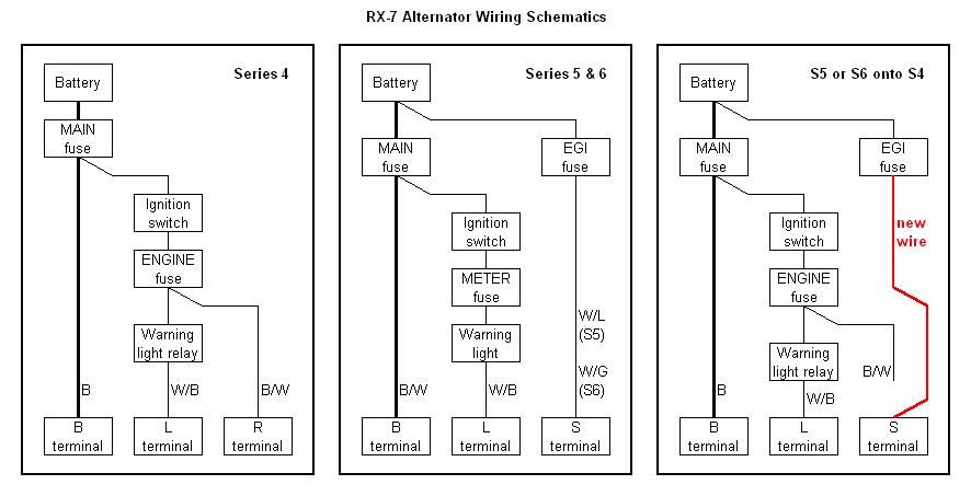
the s4 alternator isn't supposed to have a 12v constant on the s terminal, run a wire to the ignition switch.
The A terminal then.
The s5 and s6 alternators are the only ones with 12v constants.
The A terminal then.
The s5 and s6 alternators are the only ones with 12v constants.
Thread Starter
Full Member
Joined: Jul 2006
Posts: 232
Likes: 0
From: kodiak
i forgot to say that yes this is an NA to T2 swap...that is y i was asking about the alternator wiring from rotaryresurrection.com...will that solve my problem....
Hailer...what do u mean by honking the alternator...
Hailer...what do u mean by honking the alternator...
Trending Topics
Needs more Displacement.
Joined: Jun 2005
Posts: 1,329
Likes: 0
From: Louisville, Ky
Thread Starter
Full Member
Joined: Jul 2006
Posts: 232
Likes: 0
From: kodiak
ok since i have an s5 alternator anyways laying around....if i get the s5 alternator..i run one wire comin from the "S" terminal to the fuse box...this is where im kinda lost..where on the fuse box do i run the wire too...and also since i have all the lites on my dash due to it not thinking the alternator is working...how do i get all my lites to turn off and work like a normal car...where do i run the "L" terminal too since thats what it shows on the diagram...
HAILERS
Joined: May 2001
Posts: 20,563
Likes: 27
From: FORT WORTH, TEXAS,USA
On a series four car the top pin on the alternator gets fed 12vdc from the ENGINE fuse. It's a switched 12vdc by turning the key to ON: http://www.mazdamark.com/fusecover.jpg
The bottom pin goes to the CPUs elec plug near your left foot. In the plug it's a White/Black wire. This wire supplies a ground to a relay in the CPU which in turn supplys a gnd to the idiot light display to make all the idiot lights come on.
You say the alternator in your car has no wiring going from it, except for the large output iwre.
So you can see, there is something wrong with the wiring right now, since the idjut lights are already on. Something is putting a gnd on the relay in the CPU right now and it shouldn't because theres no wiring coming off the alternator.
Its most probable cause is that you have a turbo EM harness on a non turbo car. This won't work unless some small alterations are made to the turbo EM harness.
These changes are made on the EM harness inside the car at two LARGE plugs that do not connect to the ECU, but mate with the Front harness. They are LARGE plugs. One has fifteen pins and the other 13 pins/sockets.
Go to the one that has fifteen pins/sockets. Go the half of the plug on the turbo EM harness. Look for the third row from the end where you'll find a Brown wire with a Red stripe and directly below it a Brown wire with black stripe (small possibility its pure black). That BrB is a ground wire for all the sensors in the EM harness and is putting the ground on the relay in the CPU. THAT is why the idjut lights are on.
The BrR wire is an output wire from the boost sensor and if you mate that plug to the front hareness it'll go directly to the engine fuse. Take my word THIS AINT' NO DAMN GOOD.
The first thing to do is measure about three or so inches back from both those two wires, and cut them. Then dead end both those wires (the cut part of the wire not attached to the plug itself) so they won't short out.
So what you could do if you want, is run two wires from the alternator. One from the top pin would go to splice into the BrR wire that you cut at the plug. The piece that's now only about three inches long.
The new bottom wire from the alternator goes to the BrB wire you just cut at the plug. The short three inch piece left at the plug.
Then reinstall the plug and turn the key to ON. All the idjut lights should come on. Start the engine and they should go out.
Even if you decide to use the series five, you still must cut those two wires I mentioned or else things will be fucked up.
If you use the series five alternator, you could get 12v switched power form the six socket green check connector near the lead coil assy area. It's the large black/white wire that is power in that plug. Run a wire from the *S* terminal, the one to the left of the keyway in the jack, over to the black/white wire in the six socket, green check connector.
Frankly I ddi not do it that way. I bought an outfit from Autozone that has a 15 amp fuse in it and two wires at each end of the outfit. One end on of it attached to one of the 10mm bolts on the engine fuse box and the other end attached to the wire going to the alternator.
Since I used the non turbo EM harness in my n/a to turbo car, the white/black wire still existed at the alternator so it went to the pin to the right of the jack in the series five alternator. Done
Last edited by HAILERS; Feb 27, 2007 at 01:44 AM.
Thread Starter
Full Member
Joined: Jul 2006
Posts: 232
Likes: 0
From: kodiak
alrite i got the wirings done...and when i started the car the idiot lites were gone but the only thing is that when it was on the "on" position my radio was on and when i started it my radio seemed like it was going to turn off then it finally did...my radio dont come on anymore...could it be a fuse...another thing is what do i do to the wires that i cut...i just black taped them each and left them alone, is that rite.....
HAILERS
Joined: May 2001
Posts: 20,563
Likes: 27
From: FORT WORTH, TEXAS,USA
The wires that were cut should have been a BROWN/RED wire. That wire is and output wire from the BOOST SENSOR and IF this had been a Turbo car, would have gone up to the boost gauge in the cluster.
IF you had NOT cut that wire and installed the turbo EM harness to the n/a Front harness, that wire would have fed 12vdc from the ENGINE fuse to the ECU pin 2B. A pin that should NEVER see over maybe three volts or so. Cutting this wire could not cause a radio problem.
The other wire you should have cut would be colored BROWN/BLACK (possibly pure black on some cars). That wire is tied to the ground wires for all the sensors in the engine bay, such as the Boost sensor, tps, afm, etc.
IF you had left that wire in place and connected it to the Front harness for a non turbo car, it would have fed a ground to a relay in the CPU which in turn would have kept all the idiot lights on all the time.
So cutting both those wires and tying them off to the harness and capping the ends should have caused NO problems.
Tell you what, pull the plug off the back of the alternator and with the key to ON, see if the wire going to the top has 12vdc on it. If it does, then pull the ENGINE fuse and go back and see if it still has 12vdc on it. It should have disappeared.
Just so I don't have to do squat, tell me this. Am I right that this is a non turbo car and you put a Turbo engine in it and used a Turbo EM harness????? That's what I understood. Right???? Series four????
I'll double check later, but if memory serves, if you cross those two wires at the alternator and start the car, it won't shut off if the key is put to OFF because you'd be backfeeding power thru the crossed wires. That's why I asked you to check the top wire for 12vddc and see if it disappears when the ENGINE fuse is pulled.
Another thing would be to see/look at the voltage on the bottom socket on the alt plug and then pull the plug off the CPU. Any and all voltgage should disappear if that is done (on that lower wire).
HAILERS
Joined: May 2001
Posts: 20,563
Likes: 27
From: FORT WORTH, TEXAS,USA
*******...i just black taped them each and left them alone, is that rite....********
Yeah. Just make sure they don't touch bare metal etc by taping the ends off. Only the BROWN/RED one could cause a problem. IT has the volage coming out of the boost sensor. That wire also is spliced to the ECU and if you should happen to ground out that BROWN/RED wire, it will cause problems. NOT radio problems but boost sensor related problems.
BY the way, does your water temp gauge and oil pressure gauge work??? Shouldn't if you used a turbo EM on a non turbo car. It can be fixed easily also (if you don't consider werking in the foot well easy {I don't consider it easy})
I'll think about the radio thing. It does not ring a bell since the EM harness has squat to do with the radio.
Thread Starter
Full Member
Joined: Jul 2006
Posts: 232
Likes: 0
From: kodiak
yes this is an NA to a turbo swap and im using the turbo harness...and this is what i did..for the alternator, i ran two fresh wires from the back to the alternator to the two wires that i had to cut on the 15 pin plug in...for the first one i spliced the brown w/red wire and ran that on the top notch on the back of the alternator and for the other wire, i ran that to the brown w/ black wire to the bottem notch of the alternator...and since i had those two spliced wires not going anywhere, i taped the ends off with black tape...
as for the temp gauge...it works since i also ran a fresh wire to the 13 pin plug in (the top right corner pin) if im correct and ran the other end to the sensor under the oil filter...it shows that it works since the first time the needle would just go all the way up but now it doesnt, i think its readin rite unless i did it wrong..
im not so sure about my oil pressure guage..i thnk u mite need to help me on that one...
Ok slightly different question. When installing a standalone and not using the idiot lights in the dash, with an S5 alternator what happens if you don't connect L to anything? There is no more stock ecu in the car to connect it to.
B is obvious -> Main fuse constant
S is obvious -> EGI fuse constant
Since these both go to constant power, why not connect them together? Is it the fuse size?
B is obvious -> Main fuse constant
S is obvious -> EGI fuse constant
Since these both go to constant power, why not connect them together? Is it the fuse size?
HAILERS
Joined: May 2001
Posts: 20,563
Likes: 27
From: FORT WORTH, TEXAS,USA
Not a problem. What they did, is have the oil pressure and water temp wires go to different plugs on the turbo vs the non turbo.
Those two plugs are the large yellow/orange ones on the EM harness. You''ve been messing with one of them, the one called X-15. The other is in the same area of the car and is called X-16.
I think I posted a jpg somewhere showing how you could move certain wires from one plug to the other. I'll see if I can find it.
HEAVY EDIT: I was wrong about the oil. Forget that. It's wire does not go to the EM harness.
But the water does. Here's a jpg of the plug X-16. Look at both plugs. See how there is a Y/W wire in BOTH plugs??? Well Y/W is the coolant temp wire. It needs to be moved from one EM plug to the other EM plug.
Don't get confused and be looking at the F half of the plugs. Only the EM half of the plugs. Your Turbo EM harness has that Y/W wire in one of the plugs. Move it to the other EM plug. Then when you mate the two halves of the plugs everything should work, more or less.
https://www.rx7club.com/forum/attach...hmentid=211369
SECOND EDIT: What you do, is remove the Y/W wire from the 15 pin plug (X-15) and move it to the 13 pin plug (X-16).
You have to remove a LgB (light green with black stripe) from that socket where the Y/W is now going to be installed.
Tie back and cover up the end of the LgB wire. It has no function in life. Right now I forget what it did. I'll mention what later.
Last edited by HAILERS; Feb 28, 2007 at 07:49 PM.
Thread Starter
Full Member
Joined: Jul 2006
Posts: 232
Likes: 0
From: kodiak
hey hailers what if u dont move anything from the x15 and just have the plug from the x16 spliced and have that piece run off with an added wire to the temp sensor...so basically i just ran one long wire to the sensor and to the spliced wire on the x16 Y/W wire....the reason y i ask is cause thats the way i did it and it now works fine but im just wondering if not having to splice that wire from the x15 will cause some electrical issues...and is my oil gauge reading rite or do i have to do some alterations...let me know so i can get that done also..thanks
HAILERS
Joined: May 2001
Posts: 20,563
Likes: 27
From: FORT WORTH, TEXAS,USA
Yeah. Leave what you did with the water temp as is. I should have read more careful.
The oil pressure should read as before the swap. It does not pass thru the EM harness so it should be ok unless the connector at the pressure sensor is touching a ground.
OR, there is another wire spliced to the oil pressure wire. ON the end of THAT wire is supposed to be a square/black condenser that bolts to a transmission bolt somewhere.
If that condenser is disconnected from the oil pressure wire and some source of ground is installed on that connector the condenser was connected to, then the gauge will peg out, but peg out all the time.
That condenser plug is SOMEWHERE below and aft of the oil pressure sender. It's a difficult area to describe. If the gauge seems to be working, leave well enough alone.
Thread Starter
Full Member
Joined: Jul 2006
Posts: 232
Likes: 0
From: kodiak
im not sure if my oil pressure gauge is working because when i start the car it goes to the middle or up there i think if i remember....but ill have to check on that ...
again sorry if i keep asking for stuff but since i got my idiot lites off..my washer fluid buzzess forever since i guess theres no washer fluid but anyways i dont have that hooked up on my hood anyways so is there anyway i can take that lite off or the sound since i dont really need it anyways...
again sorry if i keep asking for stuff but since i got my idiot lites off..my washer fluid buzzess forever since i guess theres no washer fluid but anyways i dont have that hooked up on my hood anyways so is there anyway i can take that lite off or the sound since i dont really need it anyways...
posting in here so i can find it later.
i have one of the problems mentioned above, the one about turning the key to off, and the car keeps runing. and the battery voltage is always on.
ill have to figure out what your talking about hailers, with the black and red wires and what not. my alt. only has the one big black wire connected also, and no 2 small wires. the car is also an S4 na to TII.
can you describe excatley what pins need to be swapped for the boost sensor and all that crap?
oh, also, my idiot lights never come on when the key is on or off. only when the coolant is low, or the hatch is open.
I'm a boost creep...
Joined: Jan 2002
Posts: 15,608
Likes: 8
From: Auckland, New Zealand
Originally Posted by rotarygod
When installing a standalone and not using the idiot lights in the dash, with an S5 alternator what happens if you don't connect L to anything? There is no more stock ecu in the car to connect it to.
B is obvious -> Main fuse constant
S is obvious -> EGI fuse constant
Since these both go to constant power, why not connect them together? Is it the fuse size?
S is obvious -> EGI fuse constant
Since these both go to constant power, why not connect them together? Is it the fuse size?
HAILERS
Joined: May 2001
Posts: 20,563
Likes: 27
From: FORT WORTH, TEXAS,USA
Originally Posted by blmcquig
posting in here so i can find it later.
i have one of the problems mentioned above, the one about turning the key to off, and the car keeps runing. and the battery voltage is always on.
ill have to figure out what your talking about hailers, with the black and red wires and what not. my alt. only has the one big black wire connected also, and no 2 small wires. the car is also an S4 na to TII.
can you describe excatley what pins need to be swapped for the boost sensor and all that crap?
oh, also, my idiot lights never come on when the key is on or off. only when the coolant is low, or the hatch is open.
i have one of the problems mentioned above, the one about turning the key to off, and the car keeps runing. and the battery voltage is always on.
ill have to figure out what your talking about hailers, with the black and red wires and what not. my alt. only has the one big black wire connected also, and no 2 small wires. the car is also an S4 na to TII.
can you describe excatley what pins need to be swapped for the boost sensor and all that crap?
oh, also, my idiot lights never come on when the key is on or off. only when the coolant is low, or the hatch is open.
Ok. Did you use the stock non turbo EM harness on the engine or install a Turbo EM harness on the car?
The plugs I'm/we're talking about are inside the passengers foot area and located up to the right. One plug is 13pins and the other 15 pins.
You NEED to have the wires connected to the alternator. The old alt plug for the non turbo was on the EM harness. The turbo car is different in that the alt plug is on the E harness on the left side of the engine. Only a fool would change out the E harness just for the alt plug and I doubt anybody ever did. Just FYI.
So what you SHOULD do imho, is to run two wires from the alt to the interior on the passengers side of the car.
You find the plug with 13 sockets/pins and pull it apart. The half of the plug that is part of the EM harness has the two wires your interested in. They are locted one above the other. One is Brown with a Red stripe and the one below that is Brown with a Black stripe (on later cars it's pure black).
You cut those two wires several inches back from the plug so you have room to work/splice you two new wires.
The part of the wire that you cut, and is still attached to the plug, is the wire that you splice the new wires to. The new wire that runs from the top of the alternator small jack is the one that gets spliced to the Brown/Red wire.
The new wire that comes from the bottom of the small plug on the alternator gets spliced to the Brown wire with Black stripe (might be pure black instead).
The alternator should work right after that, IF damage hasn't happened yet. Another thing, where you cut those two wires.......the part of each cut wire that IS NOT now attached to that plug anymore, should be capped off at the ends so they can't touch bare metal. Just string tie 'em back and tape over the end or use shrink tubing etc.
Mabe i'll give a better description of the location of the plug later or someone else can. I don't like getting under the dash area at all. Maybe later.
There are other ways to wire those two wires to the alternator, BUT I think it's important that you take care of cutting those two wires AT the plug mentioned because they're backfeeding voltage and ground signals that don't belong there.
HAILERS
Joined: May 2001
Posts: 20,563
Likes: 27
From: FORT WORTH, TEXAS,USA
Maybe it'd help to look at the attachec jpg.
This is the plug. It comes in two halves. One side is labled (F) for front harness.
The other half is labled (EM) and is the harness that attaches to the Engine. It's the emissions harness.
Just look at the EM half of the plug. See how some colors have ( ) around them???? Those particular colors are what you'd see in a Turbo EM harness.
So if you have a Turbo EM harness in you non turbo car, the colors you'll see will be the BrR on top and BrB just below.
But on the non turbo EM harness those colors are BW (black/white) on top and just below WB (white/black).
The functions of the BW and WB are entirely different than the functions for the BrR and BrB wires.
So you want to make thing RIGHT. You do that by doing what I said in the other post above. You cut the wires at the EM half of the plug and attach a wire to each and run it to the small jack on the alternator.
Where the plug show BW is where the wire from the top of the alt plug goes. Where the plug shows WB is where the wire from the bottom of the alt jack goes.
By the way, the BrR wire on the turbo EM harness comes from the output of the boost sensor. The BrB wire is a gnd wire that attaches to all the sensors in the EM harness.
Also, see the (YW) wire????? That is the wire on the turbo EM harness that goes to the water temp sender. It needs to be moved to another plug all together. It needs to be moved to the plug called X-16 OR run another wire from the water sender to that YW wire and splice it to the YW. Make sense???
There are other ( ) wires on that plug that are not *right* so to speak, but do little if any harm in life if left alone as they are right now. I know what each does in life.
Just in case.....I never ever look at pm's unless selling something.....ever.
Last edited by HAILERS; Mar 1, 2007 at 09:14 AM.
if it helps ( i did this) the two alternator wires you need to tap into are in the same plug the wiper harness is on. when you removed the wiper harness from the engine harness if you chose to keep your wipers and such, you would of had to clip two wires. these were the alternator wires. so cut the connector off of the engine harness and run wires to that plug under the dash (where the wiper harness connects). just match up the colors and your done. this was on a 86 na. not sure if it will be different on newer ones.