
Activating Aux. Ports & VDI with RPM Switches

Thread Starter
Joined: Mar 2008
Posts: 8,718
Likes: 6
From: San Diego, CA
Activating Aux. Ports & VDI with RPM Switches
For S4 NA owners wanting to control the aux. port actuators with an RPM switch, solenoid & air pump, this is how I did it. In my case, I was using an S5 NA intake manifold, so I also had an RPM switch and solenoid to control the VDI system. This setup used the stock air pump, where some others have used an electric air pump. Many electric pumps can be overworked by constant use, but the stock mechanical pump can be used over and over again. This was also done with emissions systems intact.
Parts List:
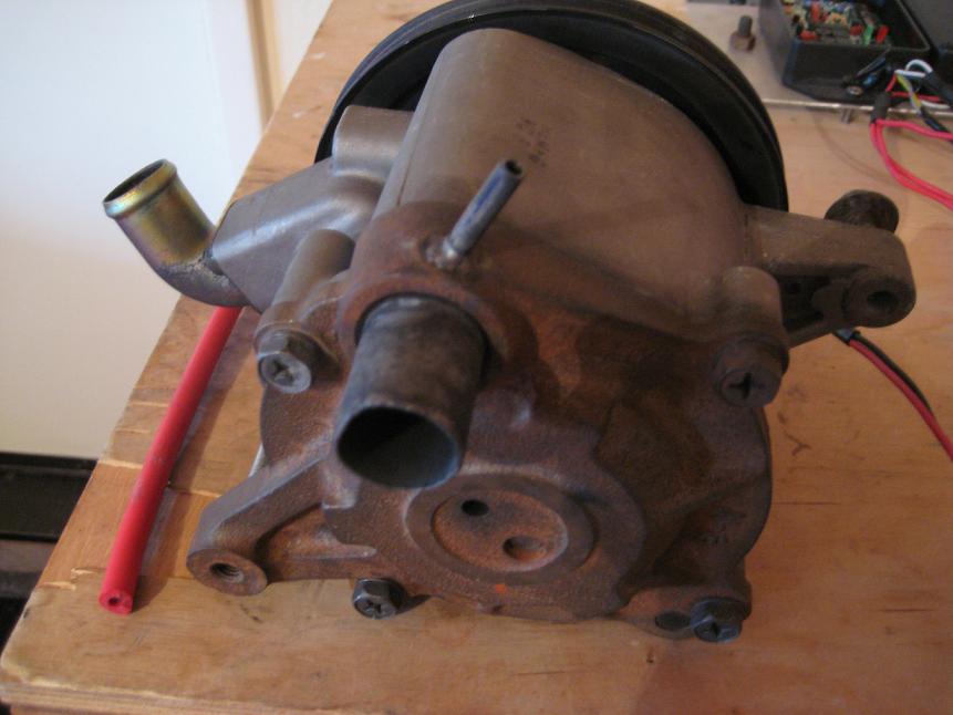
A hose from this nipple was run to a tee, and then to both of the emissions solenoids. I made a small bracket for the solenoids, and mounted it to the passenger shock tower. From one solenoid, a line was run to the metal hardline used by the S4 aux. port actuators (normally connected to the split air pipe). A line from the second solenoid was run up to the VDI valve.
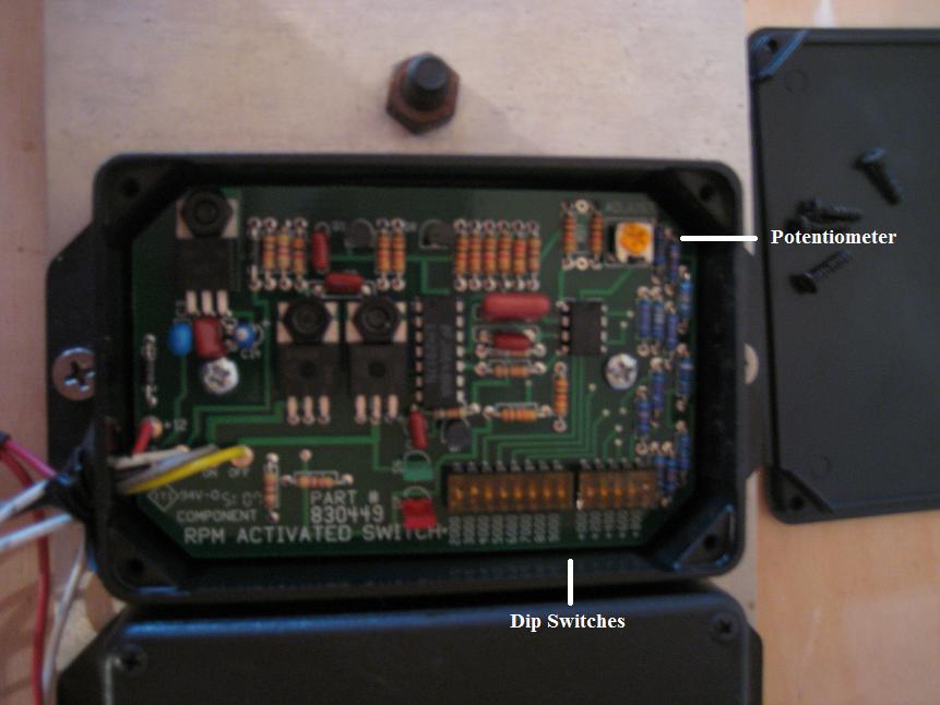
The RPM switches are very simple. They have a wire that can be connected to the diagnostic connector on the leading coil. This is where the tach signal comes from. The trailing coil also has a connector like this. To set the trigger point, a series of dip switches are adjusted to the desired RPM. A potentiometer allows some fine tuning to get the trigger just right. I set the aux. ports to open at 3800 RPM, and the VDI at 5200 RPM. These are the stock S4 and S5 settings.
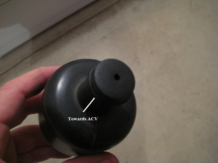
Once I got everything connected, I realized the relief valve on the ACV was opening at 3500 RPM. This created a large pressure drop between the air pump and the actuators/VDI, which was causing them to close shortly after opening. To solve this, I took a small plastic plug and stuck it in the air silencer tubing. I drilled a small ~1/4" hole in the plug to allow air to escape, but this modification kept the overall pressure high enough to keep the actuators and VDI open. Roughly 2 psi is needed to keep everything happy.
I used this setup for about 6 months without any trouble at all. The pressures were low enough not to damage the diaphragms in the actuators, but high enough to keep everything functional.
Parts List:
- 2 RPM Switches (http://www.summitracing.com/parts)/SUM-830449?part=SUM-830449
- 2 Emissions Solenoids (stock EGR solenoids work for this)
- 1 Barbed 1/8" Hose Fitting (http://www.mcmaster.com/#barbed-hose-fittings)
- ~5 ft. vacuum hose
A hose from this nipple was run to a tee, and then to both of the emissions solenoids. I made a small bracket for the solenoids, and mounted it to the passenger shock tower. From one solenoid, a line was run to the metal hardline used by the S4 aux. port actuators (normally connected to the split air pipe). A line from the second solenoid was run up to the VDI valve.
The RPM switches are very simple. They have a wire that can be connected to the diagnostic connector on the leading coil. This is where the tach signal comes from. The trailing coil also has a connector like this. To set the trigger point, a series of dip switches are adjusted to the desired RPM. A potentiometer allows some fine tuning to get the trigger just right. I set the aux. ports to open at 3800 RPM, and the VDI at 5200 RPM. These are the stock S4 and S5 settings.
Once I got everything connected, I realized the relief valve on the ACV was opening at 3500 RPM. This created a large pressure drop between the air pump and the actuators/VDI, which was causing them to close shortly after opening. To solve this, I took a small plastic plug and stuck it in the air silencer tubing. I drilled a small ~1/4" hole in the plug to allow air to escape, but this modification kept the overall pressure high enough to keep the actuators and VDI open. Roughly 2 psi is needed to keep everything happy.
I used this setup for about 6 months without any trouble at all. The pressures were low enough not to damage the diaphragms in the actuators, but high enough to keep everything functional.


Joined: Dec 2006
Posts: 2,859
Likes: 13
From: Sterling Heights, MI
Nice writeup, I'll probably end up doing mine this way too, because of the issues with electric pumps that you mentioned. Hopefully I can find my mounting hardware... 
Good call on plugging the ACV relief. Way back in 2005 I tried the electric air pump solutions. They are kind of a hassle, and they do draw additional current. Some pumps are more reliable than others.
The factory solenoids in question are very simple. They are three way valves. One port is vented to atmosphere through a filter. One port is connected to your pressure source. The third port is the output port, which goes to your actuator. Normally the solenoid will vent the actuator out through the filter--air flows from the output port to the filter. When the solenoid is engaged by +12V, the solenoid switches so that air flows from the pressure source to the output port and then to the actuator. You'll find this kind of solenoid on all sorts of cars.
The FD uses two of these types of solenoids (with the filter) for the turbo control actuator in the exhaust manifold. Two other solenoids are used, except instead of a filter on one port there is another nipple. One of these FD solenoids is used for the charge control valve (a butterfly valve in the Y pipe connecting the turbos) and one for the charge relief (a blowoff valve type of deal used during prespool. By having 3 ports the FD switches between vacuum and pressure for the actuators.
Thread Starter
Joined: Mar 2008
Posts: 8,718
Likes: 6
From: San Diego, CA
If you don't have an ACV, you could just do like you suggested and hook the air pump directly to some sort of dump hose. Some large heater hose will work. When the relief valve in the ACV opens, that's basically what you have anyway. The trick is partially blocking the path so enough pressure builds up.
Thread Starter
Joined: Mar 2008
Posts: 8,718
Likes: 6
From: San Diego, CA
Only 2 months late, but...
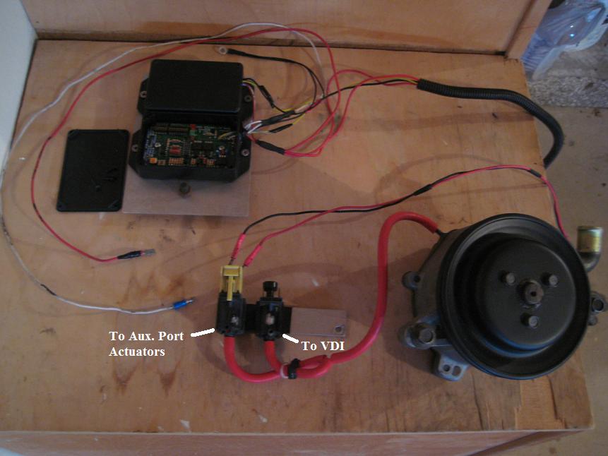
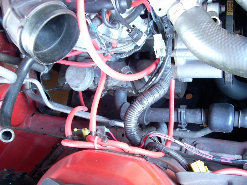
This is the only picture I have of the solenoid/air pump setup from when this was on the car. The 2 solenoids are attached to the strut tower with a little sheet metal bracket. The line from the air pump can be seen, as well as the 4 wires coming from the RPM switches, which were mounted in the area between the headlights (by the relays).
This is the only picture I have of the solenoid/air pump setup from when this was on the car. The 2 solenoids are attached to the strut tower with a little sheet metal bracket. The line from the air pump can be seen, as well as the 4 wires coming from the RPM switches, which were mounted in the area between the headlights (by the relays).
Last edited by RotaryRocket88; Dec 6, 2011 at 10:05 PM.

Thread
Thread Starter
Forum
Replies
Last Post
ncds_fc
New Member RX-7 Technical
1
Aug 15, 2015 10:06 AM