91 Vert -- Painting in progress Crystal White -- Lots of pictures

 04-10-06, 12:50 AM
#102
Rotary Enthusiast
Thread Starter
Join Date: Aug 2002
Location: Kansas
Posts: 1,273
Likes: 0
Received 0 Likes
on
0 Posts
If you look closely in some of those engine bay pics you'll also see that I've mounted some additional lines, painted lots of bolts and nuts, and little stuff like that -- nothing major, but got the brakes bled (new MC) and clutch is bled as well.
Speaking of bled -- my neighbor came over and helped me drop the motor in -- was actually a fairly easy job although those tight Banzai poly mounts gave me some fits (not the mount's fault mind you). To get the driveshaft in place, I needed to lower the front half of my new exhaust (since I had already mounted prior to dropping the engine in place). But the funny thing was that during the course of all of this my hands had gotten pretty slippery with gear & tranny oil & such and I was under the car pulling the rubber donuts off the exhaust. This is where the "bled" part comes in -- I was pulling fairly hard on the donut and just didn't have a good grip on it and "SMACK" -- my hand slipped off the donut and of course hit me right in the nose. Yep, gave myself a bloody nose -- too bad my neighbor missed it -- I told him later the excitement started about 10 minutes after he left. After I did all that I realized I forgot to throw the washers on the mounts so the next day I ended up raising the motor back up and having additional problems getting it all lined up and back together. Luckily having an extra brain on hand of another friend, he suggested elongating some holes in my mounts. These are custom made mounts, so not a total surprise that we might have been off a little bit. After redrilling/cutting the mounts everything slid into place very nicely (with the washers in the right place btw).
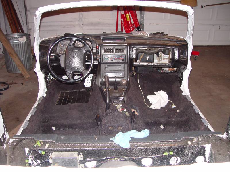
Anyway, a few more pics... I mounted the tranny at the same time, so now my son can play with the gearshift again -- he's been really concerned about that for awhile. "Dad, when is that thing going to be in the car again? - That shift-thing..."
Interior shot with noticable shifter (no ****) in the middle:
Also went ahead and mounted the A/C heat exchanger and oil cooler (not visible)
Which by the way most of this crap has been painted with high-temp gloss black before being put in. This is why it takes me freaking forever to do anything. And knowing that the paint won't last very long is not that encouraging. Ohwell, at least it will look nice for this thread.
I also bought a FMIC off of EBay and mounted it. It's a bar & plate 450x300x76mm core (in inches roughly 17 3/4 x 11 3/4 x 3) with 3" in/outlets. Seems like a quality piece, but honestly have nothing to compare it to except for an old Starion core that's quite unimpressive compared to this bar & plate one. Welds seem nice and it just looks friggin' cool -- I'm sure that counts for something! My goal was to get the largest sized possible but I wanted to fit it behind the bumper reinforcement (minor trimming was okay). I just didn't want to have to take the bumper reinforcement off. Also, if I measured correctly, then it should also fit between the headlights directly in front of the A/C exhanger with the in/outlets just hanging below the sheet metal. So when I got it, a real test fit was in order. I didn't get a good picture before I mounted it and of course I have cardboard protecting it right now, so there isn't much to see -- but here it is anyway.
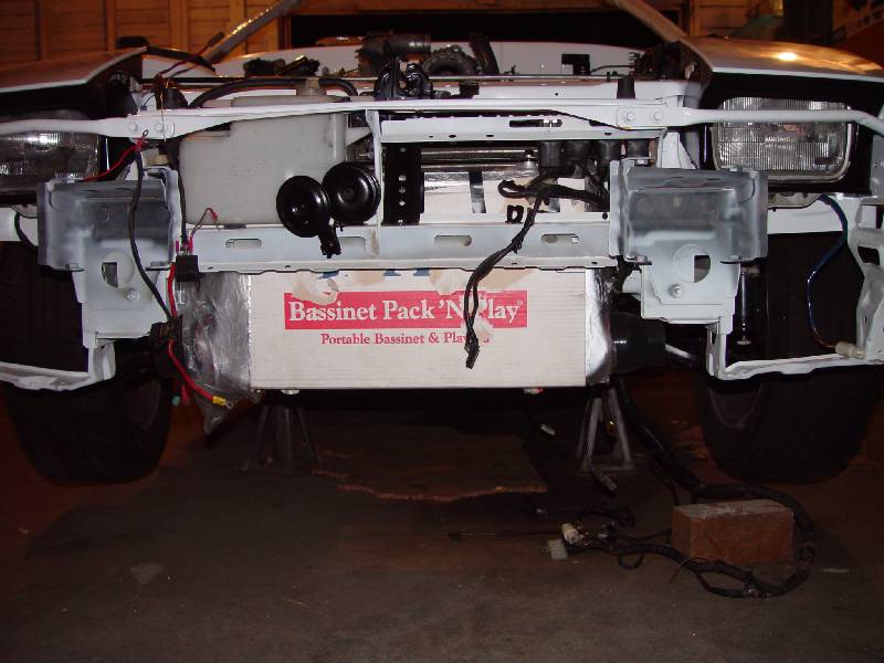
Front view:
Top view of mount:
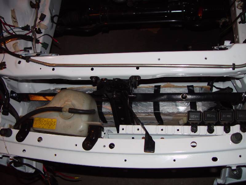
As it turns out, the thing does fit VERY nicely between the headlights in that open space. And it took me a short while, but I fabbed my own cross bar for mounting and have it spaced just right such that the in/outlets hang just below the sheet metal where I planned. It also did not require any cutting (just drilling a few holes). Obviously I'll have to cut holes for the pipes, but I expected that. Also, I was pleased to see that my coolant overflow bottle still fit in the stock location -- although I did move my horns to be in front of the coolant bottle as you can see in that first FMIC pic. I believe that if I was careful enough and possibly modified the AC dryer mount that I could have mounted it in stock location also -- however my plan is to move it clear up to the passenger side firewall. I've been "rebending" the A/C lines to make it fit there. So far it's seems like it's going to work, but I haven't done the final mounting of the dryer, so time will tell if everything will line up right. I'll get more details & pictures on that once it's actually in place.
I'm leaving out a lot of the little details, but here is a quick list of the recent accomplishments:
*Painted the headlight covers
*Mounted headlights
*Painted headlight "surround"
*Painted hood & trunk brackets
*Mounted hood & trunk brackets
*Painted a hundred and one bolts & nuts & various brackets
*Mounted & bled MC & clutch cylinder
*Bought & mounted FMIC
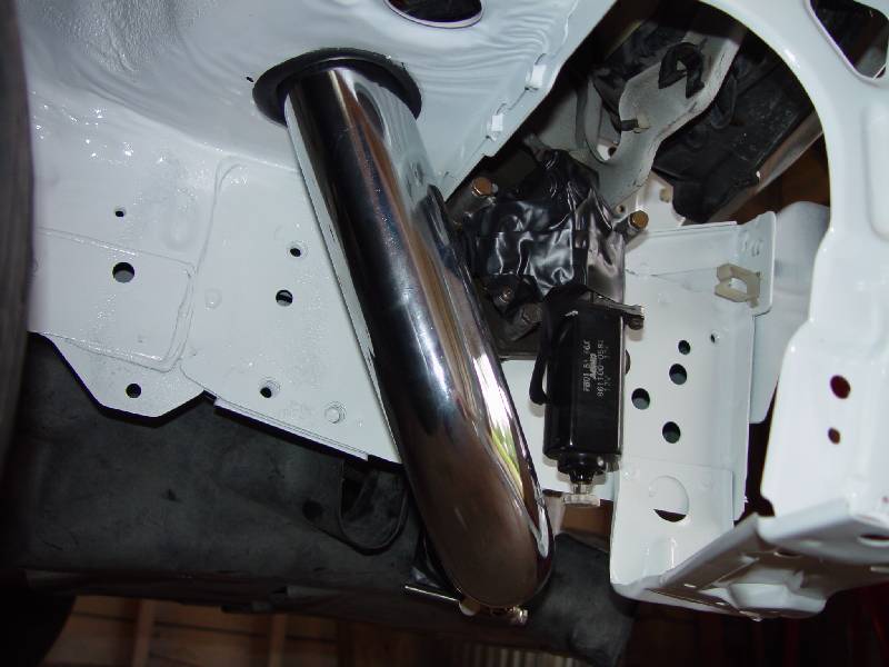
*Bought & mounted dual SS turbo-back exhaust (Motoria)
*Dropped the motor & tranny in
*Driveshaft connected
*Fuel filter bracket painted & mounted (with filter)
*Rebending a/c lines for better placement of components (to aid in having room for FMIC)
*Bought FMIC pipe kit from Ebay (not mounted yet)
*Mounted battery in trunk
*????
I'm sure there's more, just can't remember it all at once. Well, that's a long enough post for now -- I welcome any comments, questions, suggests, smart remarks, etc.
Thanks for looking!
Speaking of bled -- my neighbor came over and helped me drop the motor in -- was actually a fairly easy job although those tight Banzai poly mounts gave me some fits (not the mount's fault mind you). To get the driveshaft in place, I needed to lower the front half of my new exhaust (since I had already mounted prior to dropping the engine in place). But the funny thing was that during the course of all of this my hands had gotten pretty slippery with gear & tranny oil & such and I was under the car pulling the rubber donuts off the exhaust. This is where the "bled" part comes in -- I was pulling fairly hard on the donut and just didn't have a good grip on it and "SMACK" -- my hand slipped off the donut and of course hit me right in the nose. Yep, gave myself a bloody nose -- too bad my neighbor missed it -- I told him later the excitement started about 10 minutes after he left. After I did all that I realized I forgot to throw the washers on the mounts so the next day I ended up raising the motor back up and having additional problems getting it all lined up and back together. Luckily having an extra brain on hand of another friend, he suggested elongating some holes in my mounts. These are custom made mounts, so not a total surprise that we might have been off a little bit. After redrilling/cutting the mounts everything slid into place very nicely (with the washers in the right place btw).
Anyway, a few more pics... I mounted the tranny at the same time, so now my son can play with the gearshift again -- he's been really concerned about that for awhile. "Dad, when is that thing going to be in the car again? - That shift-thing..."
Interior shot with noticable shifter (no ****) in the middle:
Also went ahead and mounted the A/C heat exchanger and oil cooler (not visible)
Which by the way most of this crap has been painted with high-temp gloss black before being put in. This is why it takes me freaking forever to do anything. And knowing that the paint won't last very long is not that encouraging. Ohwell, at least it will look nice for this thread.
I also bought a FMIC off of EBay and mounted it. It's a bar & plate 450x300x76mm core (in inches roughly 17 3/4 x 11 3/4 x 3) with 3" in/outlets. Seems like a quality piece, but honestly have nothing to compare it to except for an old Starion core that's quite unimpressive compared to this bar & plate one. Welds seem nice and it just looks friggin' cool -- I'm sure that counts for something!
My goal was to get the largest sized possible but I wanted to fit it behind the bumper reinforcement (minor trimming was okay). I just didn't want to have to take the bumper reinforcement off. Also, if I measured correctly, then it should also fit between the headlights directly in front of the A/C exhanger with the in/outlets just hanging below the sheet metal. So when I got it, a real test fit was in order. I didn't get a good picture before I mounted it and of course I have cardboard protecting it right now, so there isn't much to see -- but here it is anyway.Front view:
Top view of mount:
As it turns out, the thing does fit VERY nicely between the headlights in that open space. And it took me a short while, but I fabbed my own cross bar for mounting and have it spaced just right such that the in/outlets hang just below the sheet metal where I planned. It also did not require any cutting (just drilling a few holes). Obviously I'll have to cut holes for the pipes, but I expected that. Also, I was pleased to see that my coolant overflow bottle still fit in the stock location -- although I did move my horns to be in front of the coolant bottle as you can see in that first FMIC pic. I believe that if I was careful enough and possibly modified the AC dryer mount that I could have mounted it in stock location also -- however my plan is to move it clear up to the passenger side firewall. I've been "rebending" the A/C lines to make it fit there. So far it's seems like it's going to work, but I haven't done the final mounting of the dryer, so time will tell if everything will line up right. I'll get more details & pictures on that once it's actually in place.
I'm leaving out a lot of the little details, but here is a quick list of the recent accomplishments:
*Painted the headlight covers
*Mounted headlights
*Painted headlight "surround"
*Painted hood & trunk brackets
*Mounted hood & trunk brackets
*Painted a hundred and one bolts & nuts & various brackets
*Mounted & bled MC & clutch cylinder
*Bought & mounted FMIC
*Bought & mounted dual SS turbo-back exhaust (Motoria)
*Dropped the motor & tranny in
*Driveshaft connected
*Fuel filter bracket painted & mounted (with filter)
*Rebending a/c lines for better placement of components (to aid in having room for FMIC)
*Bought FMIC pipe kit from Ebay (not mounted yet)
*Mounted battery in trunk
*????
I'm sure there's more, just can't remember it all at once. Well, that's a long enough post for now -- I welcome any comments, questions, suggests, smart remarks, etc.
Thanks for looking!
04-10-06, 12:52 AM
#103
Rotary Enthusiast
Thread Starter
Join Date: Aug 2002
Location: Kansas
Posts: 1,273
Likes: 0
Received 0 Likes
on
0 Posts
Originally Posted by theagavejazz
Beautiful, do you know if those mufflers are available seperately?
https://www.rx7club.com/group-buy-center-69/gb-fc3s-complete-ss-turbo-back-dual-exhaust-470213/
 Don't wait another 2 months to update this thread. Keep us updated.
05-04-06, 10:02 PM
Don't wait another 2 months to update this thread. Keep us updated.
05-04-06, 10:02 PM
#106
Rotary Enthusiast
Thread Starter
Join Date: Aug 2002
Location: Kansas
Posts: 1,273
Likes: 0
Received 0 Likes
on
0 Posts
Alright folks, I have a few more updates to make...
I recently purchased a generic 2.5" IC pipe kit off of Ebay -- didn't really take pics of it before I started installing it, but it's the basic generic kit that has 2 bends of 3 different angles and 2 straight pieces. It also had silicone connectors as well as 2 90 degree connectors. I was also surprised to find actual tbolt clamps included for the price, but honestly they are cheap clamps -- but for now they should do nicely. The funny thing is I actually ordered black pipe -- I thought the black would go nicely with the other black accents I have in my bay, but when it got here, everything was chrome. Seller stated "yeah, we've had other buyers say the same. We complained to the manufacturer, but not much we can do". Wow, way to make an effort there buddy -- ohwell, I had debated between the chrome and black anyway, so I wasn't heartbroken. Maybe sometime I'll powdercoat these or something -- then again, maybe not.
Anyway, on to the details & pics of the install...
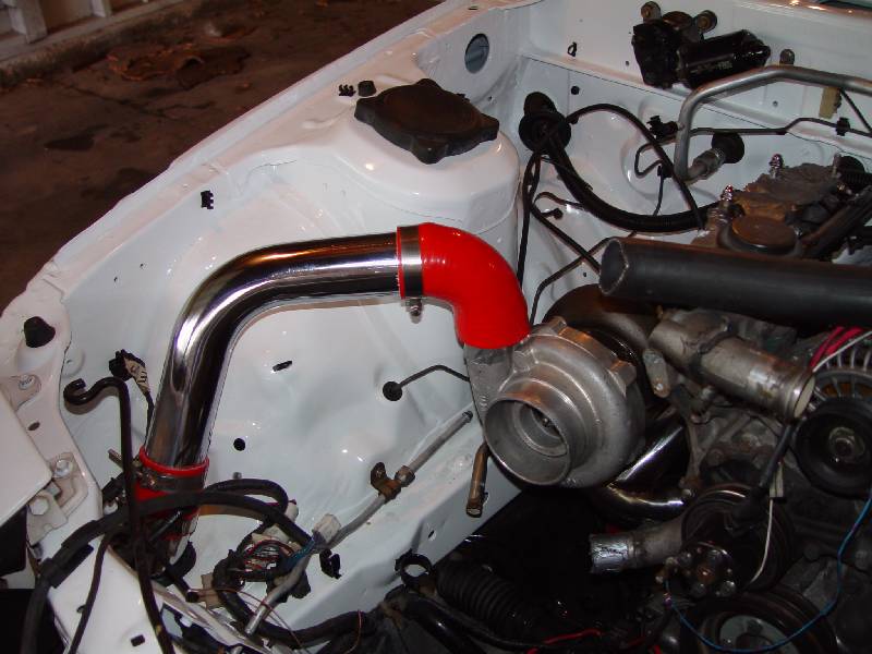
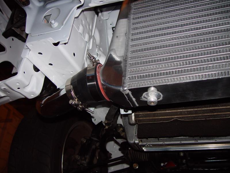
Install was actually easier than I thought -- although it did take a little adjusting to get everything lined up the way I wanted. First pic is on the drivers side on the post-IC pipe.
I actually just used a pipe-expander on the existing hole on that side to simply make the hole big enough for a 2.5" pipe to fit through. I ended up cutting some of the lip off because it got to be fairly big and used fuel hose around the hole to protect the pipe and eliminate banging, etc. You'll probably notice in one of the pics I cut it too short -- I'll go back and fix that later.
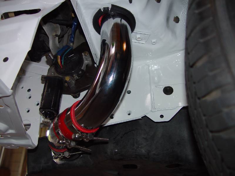
2nd pic shows the underside of that hole and the pipe from the IC to the hole. Should be fairly self explanatory, but note the very short bend coming off of the FMIC.
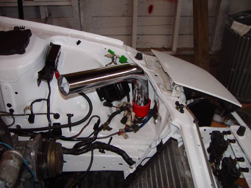
3rd pic is a top view of the pipe from the turbo down through the area behind the headlight.
A lot of the other installs that I looked at (particularly the Greddy kits) actually went through the vertical wall behind the headlight. In all my mock-ups and estimating and what-not, I couldn't figure out why it wouldn't work to go through a hole that was placed similarly to the hole on the drivers side on the horizontal metal, so that's what I did. I actually used a 2.5" hole-saw as a template and simply slipped the small pilot bit through an existing hole there and clamped the 2.5" hole-saw in place. I then used a plasma cutter (freaking handy!!) to cut around the hole-saw for a nice round hole in a matter of seconds. Then I used the pipe expander again to get it to the size I needed for the pipe to fit through (and the fuel line protection again). Turned out nicely and somehow I ended up not having to use an extra bend on that side like I did the drivers side. HOWEVER, the angle isn't real great and tends to put the couplers at a point where they may not hold under boost -- so I may actually go back and add that bend anyway for a smoother look and fit.
4th pic is the front view of the drivers underside pipe from IC to hole.
5th pic is the same pipe from a side view.
Overall I'm VERY pleased with the outcome of the pipes so far. I was honestly pretty intimidated by the effort and fabrication that might be needed to fully mount and pipe the FMIC, but honestly it turned out easier than I thought -- although a lot of careful and patient planning went into it and I studied pretty hard before I cut anything. Obviously as evidenced by the very first pic, I still need to put the intake together for final fitment, but that should be fairly painless to do later on...
continuing>>>
I recently purchased a generic 2.5" IC pipe kit off of Ebay -- didn't really take pics of it before I started installing it, but it's the basic generic kit that has 2 bends of 3 different angles and 2 straight pieces. It also had silicone connectors as well as 2 90 degree connectors. I was also surprised to find actual tbolt clamps included for the price, but honestly they are cheap clamps -- but for now they should do nicely. The funny thing is I actually ordered black pipe -- I thought the black would go nicely with the other black accents I have in my bay, but when it got here, everything was chrome. Seller stated "yeah, we've had other buyers say the same. We complained to the manufacturer, but not much we can do". Wow, way to make an effort there buddy -- ohwell, I had debated between the chrome and black anyway, so I wasn't heartbroken. Maybe sometime I'll powdercoat these or something -- then again, maybe not.
Anyway, on to the details & pics of the install...
Install was actually easier than I thought -- although it did take a little adjusting to get everything lined up the way I wanted. First pic is on the drivers side on the post-IC pipe.
I actually just used a pipe-expander on the existing hole on that side to simply make the hole big enough for a 2.5" pipe to fit through. I ended up cutting some of the lip off because it got to be fairly big and used fuel hose around the hole to protect the pipe and eliminate banging, etc. You'll probably notice in one of the pics I cut it too short -- I'll go back and fix that later.
2nd pic shows the underside of that hole and the pipe from the IC to the hole. Should be fairly self explanatory, but note the very short bend coming off of the FMIC.
3rd pic is a top view of the pipe from the turbo down through the area behind the headlight.
A lot of the other installs that I looked at (particularly the Greddy kits) actually went through the vertical wall behind the headlight. In all my mock-ups and estimating and what-not, I couldn't figure out why it wouldn't work to go through a hole that was placed similarly to the hole on the drivers side on the horizontal metal, so that's what I did. I actually used a 2.5" hole-saw as a template and simply slipped the small pilot bit through an existing hole there and clamped the 2.5" hole-saw in place. I then used a plasma cutter (freaking handy!!) to cut around the hole-saw for a nice round hole in a matter of seconds. Then I used the pipe expander again to get it to the size I needed for the pipe to fit through (and the fuel line protection again). Turned out nicely and somehow I ended up not having to use an extra bend on that side like I did the drivers side. HOWEVER, the angle isn't real great and tends to put the couplers at a point where they may not hold under boost -- so I may actually go back and add that bend anyway for a smoother look and fit.
4th pic is the front view of the drivers underside pipe from IC to hole.
5th pic is the same pipe from a side view.
Overall I'm VERY pleased with the outcome of the pipes so far. I was honestly pretty intimidated by the effort and fabrication that might be needed to fully mount and pipe the FMIC, but honestly it turned out easier than I thought -- although a lot of careful and patient planning went into it and I studied pretty hard before I cut anything. Obviously as evidenced by the very first pic, I still need to put the intake together for final fitment, but that should be fairly painless to do later on...
continuing>>>
05-04-06, 10:15 PM
#107
Rotary Enthusiast
Thread Starter
Join Date: Aug 2002
Location: Kansas
Posts: 1,273
Likes: 0
Received 0 Likes
on
0 Posts
Seats are also now installed -- honestly it was harder to install these than I thought it would be and actually required more time and work and blood and sweat and cursing and pain and grinding and cutting and cursing and fabrication and drilling and cursing than it did the FMIC and IC mounting...
Did I mention this was a pain in the rear??
Anyway, the DAD seats are in and I'm happy with the results, I'm just irritated that it took so long and was such a painful experience...
View from the front -- my son is VERY happy the seats are in now!
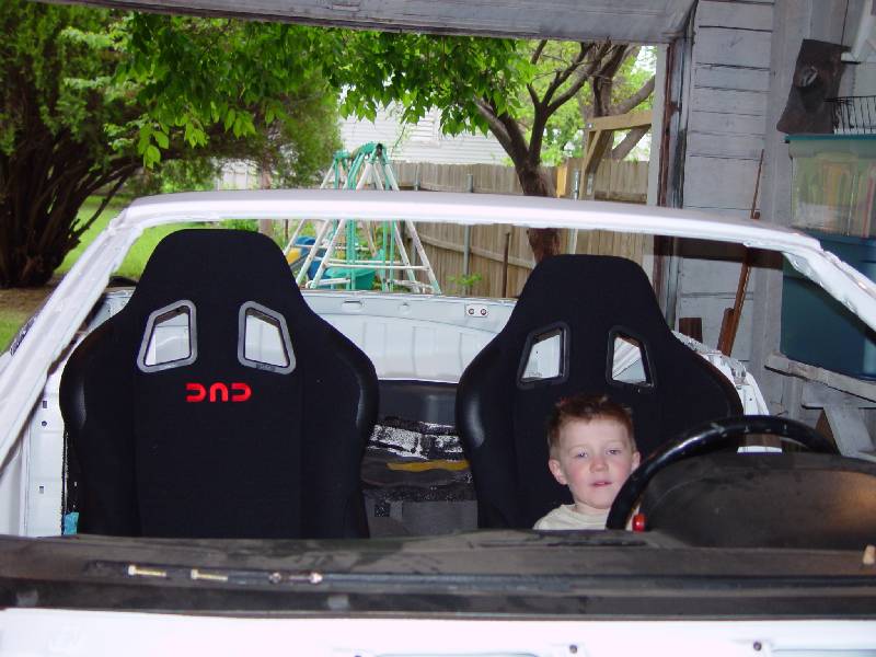
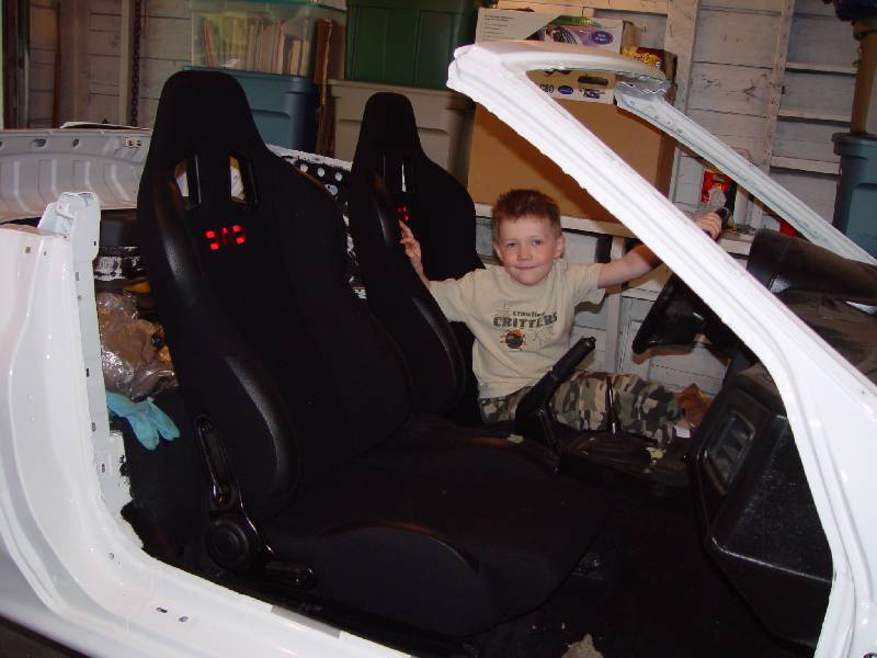
View from the passenger side.
View from the rear.
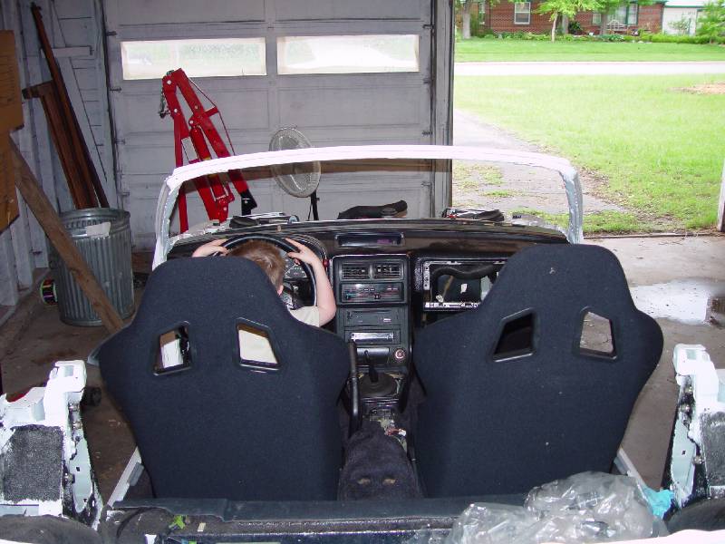
I know these last 2 pictures will not do my brackets any justice, but I did not take a picture of the brackets before installation -- mostly because I just wanted to get them in, but also because I didn't want you to laugh at my terrible welding. Honestly I could care less how they look since you can't see them.
Anyway, the seats came with their own sliders, but they were positioned slightly narrower (closer together) than the factory sliders are. So basically my idea was that I could use pieces of angle iron to bolt the sliders to and then make "legs" on the angles to bolt to the existing mount locations on the floor.
The good news was that I could use my donor car as the guinea pig for fitment while I was welding and cutting and drilling the new rails...
Here are the pics of the drivers and passengers side floors -- they really don't do the actual design justice, but I think you'll get what I mean.
Driver's side:
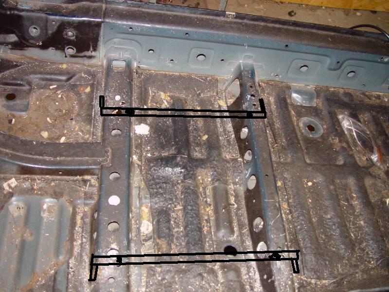
Passenger's side:
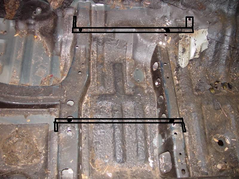
Essentially my design worked, it just took awhile to get the fitment right since I had to grind away parts of the angle for it to fit against the floor. I also realized I had to cut the seat bolts short so they would allow the seat to fit down flush against the rails. Many hours later, the whole thing came together and I was happy with the results. The seats fit nice, but they may actually be a bit big for the FC's small interior. Won't really know for sure until everything is in place, but for now, I'm satisfied.
continuing>>>
Did I mention this was a pain in the rear??
Anyway, the DAD seats are in and I'm happy with the results, I'm just irritated that it took so long and was such a painful experience...
View from the front -- my son is VERY happy the seats are in now!
View from the passenger side.
View from the rear.
I know these last 2 pictures will not do my brackets any justice, but I did not take a picture of the brackets before installation -- mostly because I just wanted to get them in, but also because I didn't want you to laugh at my terrible welding.
Honestly I could care less how they look since you can't see them.Anyway, the seats came with their own sliders, but they were positioned slightly narrower (closer together) than the factory sliders are. So basically my idea was that I could use pieces of angle iron to bolt the sliders to and then make "legs" on the angles to bolt to the existing mount locations on the floor.
The good news was that I could use my donor car as the guinea pig for fitment while I was welding and cutting and drilling the new rails...
Here are the pics of the drivers and passengers side floors -- they really don't do the actual design justice, but I think you'll get what I mean.
Driver's side:
Passenger's side:
Essentially my design worked, it just took awhile to get the fitment right since I had to grind away parts of the angle for it to fit against the floor. I also realized I had to cut the seat bolts short so they would allow the seat to fit down flush against the rails. Many hours later, the whole thing came together and I was happy with the results. The seats fit nice, but they may actually be a bit big for the FC's small interior. Won't really know for sure until everything is in place, but for now, I'm satisfied.
continuing>>>
05-04-06, 10:30 PM
#108
Rotary Enthusiast
Thread Starter
Join Date: Aug 2002
Location: Kansas
Posts: 1,273
Likes: 0
Received 0 Likes
on
0 Posts
Last update for now...
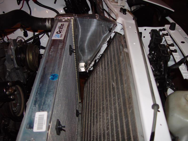
I have a Griffin radiator that I was trying to figure out how to mount and essentially designed a 'triangle' shaped mount for each side of the rad to bolt to and then bolt to the original rad mounts on the car. I'll have more pics of this when it's actually installed -- and it will probably make more sense at that point also. But anyway, I set the radiator in place where I thought it should be mounted -- more in a vertical fashion than the original which layed forward. Since that meant the top was farther away from the mount than the bottom, it needed that 'triangle' shape that I mentioned. So, I used cardboard to get the size right and then took sheet aluminum, cut to the right size, bent it into a 'box' and then took it to a professional welder here in town to weld the 'box' shut and weld it to the radiator. I think it turned out nicely and makes a nice shroud for the sides of the radiator. I do sort of wish he would have welded a longer seam on each side of the rad, but if it's going to work, it should work with what he did...
A couple of pics of the inside and outside of the mounts already welded to the rad.
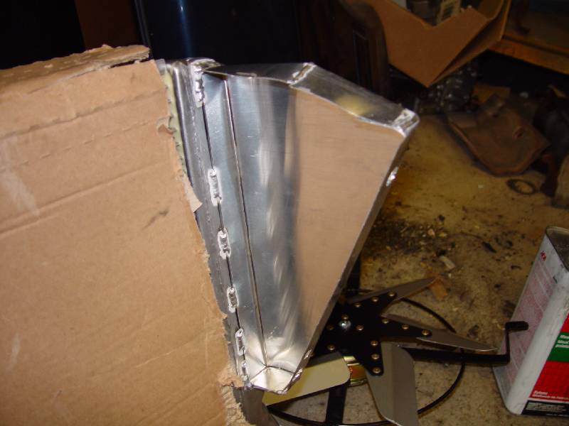
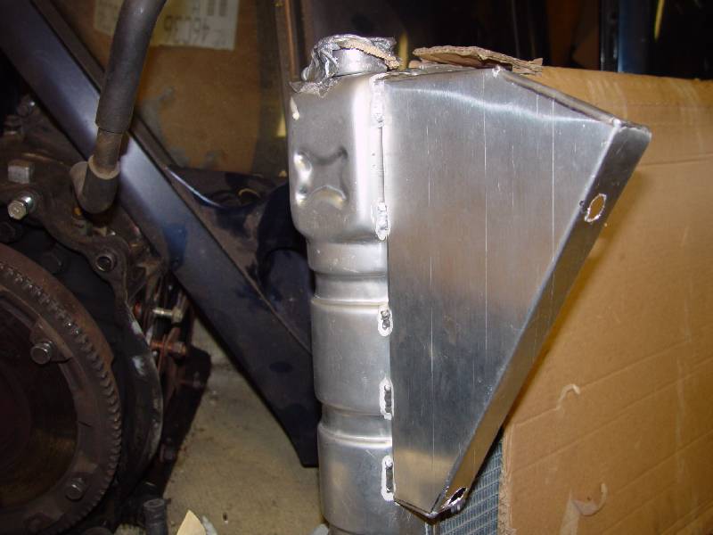
Like I said, I'll get more pics once the radiator is actually bolted in so I think it will be more evident what I was doing. I do think the box will be strong enough to hold, however, I may go ahead and build a few reinforcments into the inside mounting points of the mounts and possibly some to go to the bottom of the radiator to support some weight. I actually had previously mounted this radiator in the other car by simply using aluminum straights and angles, so I may re-use the design I had for the bottom for that extra support. Hopefully this all works out -- we'll see if it holds up...
I'll probably bolt the radiator in this weekend and a few other little things and give you another short update after all that. Next tasks to do are the rad, intake, wiring, fuel & oil lines, coolant lines, a/c lines, etc.
On a final and sort of off-topic (and sad) note, I had a bit of a bad week last week. I was actually out of town (in Orlando for a conference) and because one side of my garage is being taken up by the RX7, my poor Dodge Ram became the sacrificial lamb.
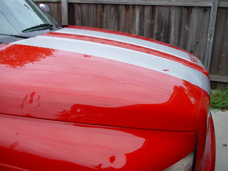
We had golfball to baseball sized hail and unfortunately my truck took the brunt of that beating. Sucked because I wasn't even here and left my wife to deal with those problems while I was gone. I still have to call insurance about it (and the other car and the house). Just didn't have everything organized enough before I left, otherwise I could probably get all 3 vehicles under cover with a little creative planning -- maybe next time...
I'll leave you with that -- as always, I welcome comments, questions, suggestions, jokes, smart remarks, etc.
Thanks for looking!!
I have a Griffin radiator that I was trying to figure out how to mount and essentially designed a 'triangle' shaped mount for each side of the rad to bolt to and then bolt to the original rad mounts on the car. I'll have more pics of this when it's actually installed -- and it will probably make more sense at that point also. But anyway, I set the radiator in place where I thought it should be mounted -- more in a vertical fashion than the original which layed forward. Since that meant the top was farther away from the mount than the bottom, it needed that 'triangle' shape that I mentioned. So, I used cardboard to get the size right and then took sheet aluminum, cut to the right size, bent it into a 'box' and then took it to a professional welder here in town to weld the 'box' shut and weld it to the radiator. I think it turned out nicely and makes a nice shroud for the sides of the radiator. I do sort of wish he would have welded a longer seam on each side of the rad, but if it's going to work, it should work with what he did...
A couple of pics of the inside and outside of the mounts already welded to the rad.
Like I said, I'll get more pics once the radiator is actually bolted in so I think it will be more evident what I was doing. I do think the box will be strong enough to hold, however, I may go ahead and build a few reinforcments into the inside mounting points of the mounts and possibly some to go to the bottom of the radiator to support some weight. I actually had previously mounted this radiator in the other car by simply using aluminum straights and angles, so I may re-use the design I had for the bottom for that extra support. Hopefully this all works out -- we'll see if it holds up...
I'll probably bolt the radiator in this weekend and a few other little things and give you another short update after all that. Next tasks to do are the rad, intake, wiring, fuel & oil lines, coolant lines, a/c lines, etc.
On a final and sort of off-topic (and sad) note, I had a bit of a bad week last week. I was actually out of town (in Orlando for a conference) and because one side of my garage is being taken up by the RX7, my poor Dodge Ram became the sacrificial lamb.
We had golfball to baseball sized hail and unfortunately my truck took the brunt of that beating. Sucked because I wasn't even here and left my wife to deal with those problems while I was gone. I still have to call insurance about it (and the other car and the house). Just didn't have everything organized enough before I left, otherwise I could probably get all 3 vehicles under cover with a little creative planning -- maybe next time...
I'll leave you with that -- as always, I welcome comments, questions, suggestions, jokes, smart remarks, etc.
Thanks for looking!!
05-04-06, 10:40 PM
#109
Senior Member
Join Date: Sep 2005
Location: Cambridge, London
Posts: 283
Likes: 0
Received 0 Likes
on
0 Posts
man thats a great job, thats gunna be one purddy turbo vert!!! Props!! thats
shittty about the truck. hail sucks
shittty about the truck. hail sucks
Last edited by re.fc3s; 05-04-06 at 10:43 PM.
05-06-06, 11:25 AM
#111
Rotary Enthusiast
Thread Starter
Join Date: Aug 2002
Location: Kansas
Posts: 1,273
Likes: 0
Received 0 Likes
on
0 Posts
Originally Posted by re.fc3s
man thats a great job, thats gunna be one purddy turbo vert!!! Props!! thats
shittty about the truck. hail sucks
shittty about the truck. hail sucks
Originally Posted by theagavejazz
wow, I love the seats.. and the rest of the car too. Superb work. You should be very proud.
Got them for a pretty good price and they definitely are snug on my body, so I hope that they'll hold me in good. I'd like to figure out something else to do w/ the seat belts, but at the moment I have the old blue vert belts to go with them. One of these days I'll find some black ones. I might go for the 4 points, but I think that looks a little "rice" if that's the only thing you have when you're running around in a daily driver (plus I'm not sure of the legality of it). When I fit the seats in the donor car long ago, the stock belt seemed to work great going through one of the holes in the seat back, so we'll see if everything still works that way or not...Thanks for the compliments!
05-27-06, 12:14 AM
#112
Rotary Enthusiast
Thread Starter
Join Date: Aug 2002
Location: Kansas
Posts: 1,273
Likes: 0
Received 0 Likes
on
0 Posts
more updates
Alright folks, time for a few more updates. Nothing really major to report, but I did make a little progress on a few things...
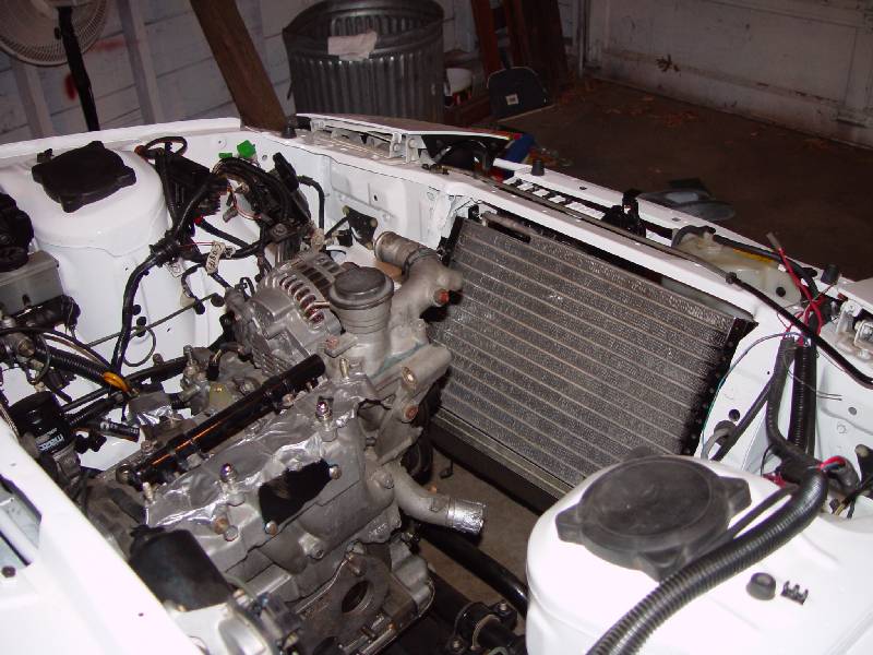
Radiator is mounted in the car now -- and it feels SOLID. I was a little concerned that the mounts might flex a bit, but it seems very stiff, so I'm happy with that. Hopefully I have no issues with the welds. A few pics of the mounted rad with the fan attached:
Back side of rad with finger chopper:
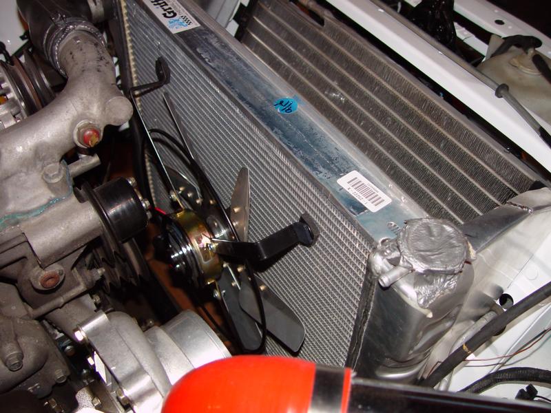
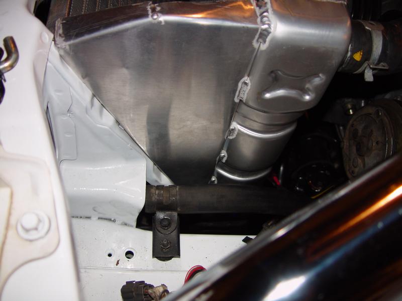
Between condenser and rad -- inside driver's rad mount visible:
Outside drivers rad mount:
Outside pass rad mount:
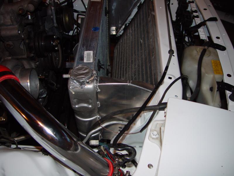
Overall I'm very pleased with the mounts and the fitment. Although I do have one concern now -- the mounts place the rad close to the intake of the turbo. I don't know for sure if I'm going to stick with that manifold, so it may or may not be a big deal -- but I'll probably consider getting a nice 90* bend to go on the turbo so I can place it out of the path of the hot air -- just not sure if there is enough room for all of that. It's my fault really -- I didn't have the turbo sitting there when I planned the rad mounts and didn't think about it's placement compared to the turbo. Anyway, we'll see how it turns out, it may be just fine...
<continued>
Radiator is mounted in the car now -- and it feels SOLID. I was a little concerned that the mounts might flex a bit, but it seems very stiff, so I'm happy with that. Hopefully I have no issues with the welds. A few pics of the mounted rad with the fan attached:
Back side of rad with finger chopper:
Between condenser and rad -- inside driver's rad mount visible:
Outside drivers rad mount:
Outside pass rad mount:
Overall I'm very pleased with the mounts and the fitment. Although I do have one concern now -- the mounts place the rad close to the intake of the turbo. I don't know for sure if I'm going to stick with that manifold, so it may or may not be a big deal -- but I'll probably consider getting a nice 90* bend to go on the turbo so I can place it out of the path of the hot air -- just not sure if there is enough room for all of that. It's my fault really -- I didn't have the turbo sitting there when I planned the rad mounts and didn't think about it's placement compared to the turbo. Anyway, we'll see how it turns out, it may be just fine...
<continued>
05-27-06, 12:20 AM
#113
Rotary Enthusiast
Thread Starter
Join Date: Aug 2002
Location: Kansas
Posts: 1,273
Likes: 0
Received 0 Likes
on
0 Posts
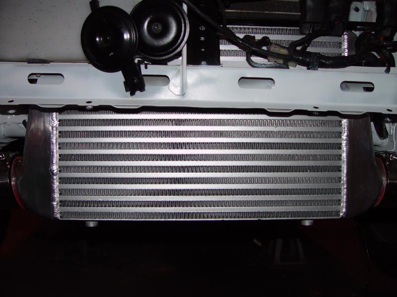
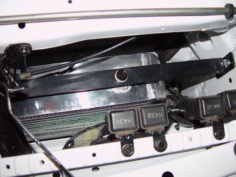
I promised some better pictures of the intercooler mounted in the car. These aren't great, but honestly there isn't much to see -- but it should give you a good idea where it fits and how it looks. I'm just happy I really didn't have to cut anything major. As I mentioned, I merely drilled 4 holes for my bracket across the top and cut the holes for the pipes to go through...
From front of car:
Top of IC showing driver's side end of mount:
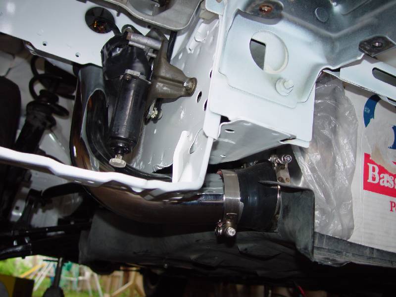
Bottom right side of IC showing starting route of pipe:
Looking up from the bottom of the IC showing clearance and placement:
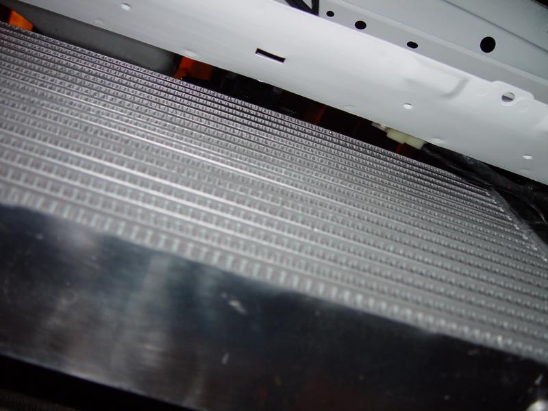
As I mentioned in previous posts, this size of IC fit very nicely and I hope since it's a good sized bar & plate that it will serve the purpose for anything I throw at it... I'm also happy to keep my bumper reinforcement in place.
<continued>
From front of car:
Top of IC showing driver's side end of mount:
Bottom right side of IC showing starting route of pipe:
Looking up from the bottom of the IC showing clearance and placement:
As I mentioned in previous posts, this size of IC fit very nicely and I hope since it's a good sized bar & plate that it will serve the purpose for anything I throw at it... I'm also happy to keep my bumper reinforcement in place.
<continued>
05-27-06, 12:38 AM
#115
Rotary Enthusiast
Thread Starter
Join Date: Aug 2002
Location: Kansas
Posts: 1,273
Likes: 0
Received 0 Likes
on
0 Posts
I also started working on some plumbing. I'm using an FD primary fuel rail machined to accept FD secondary injectors. That's mounted in place and I'm using the stock fitting on the front side of that rail -- I simply cut the banjo fitting off so I have a hose end to plumb to. I also tapped the back side of the rail to accept a barb fitting thanks to another thread I found with the details on that method. I've also got an Aeromotive FPR that I'll be mounting and plumbing in, but haven't figured out exactly where or how that will fit in the picture.
Don't have any pics of the fuel rail, but hopefully the description explains it -- I'll try to get out and take some pics when I have the complete fuel plumbing done.
Also today I went to several hydraulic shops trying to find someone who carried another banjo fitting I could use for my oil cooler lines. I had 2 banjo fittings already that I cut the old hose off of from the oil-cooler ends, but I was hoping to find a banjo fitting for the top of the block too. (FYI the back oil cooler line actually goes to the top of the block under the oil filter on an RE in case you're wondering).
Everywhere I went basically said they'd never seen a banjo that big so I felt like the scrap yard was my only hope. Finally I decided I would do a bit more research and found the thread size of the banjo bolts (18mm x 1.5 pitch). My hope restored, I figured I would be able to find a suitable fitting of that size instead of the banjo. I went back to one of the shops I visited and they had a nice swivel style fitting and a 90* barb. They then clamped on some high pressure high temp hose. He was feeling good and I got out of there for 12 BUCKS!!!!! Yep that's right, I replaced my oil cooler lines for 12 dollars, 12 bucks, 1200 pennies. Needless to say, I was ecstatic since the alternative is to go stainless and approach the $200 mark.
I then went and got raped by OReillys for the copper washers for 2 pairs it was $4.9x with tax. I was in too good of mood to complain much (although I did double check at the Ace close by to see if they were cheaper). But all told, I replaced the whole thing and got them installed tonight. Total price was just under $17 by reusing the 2 banjo fittings on the cooler, the short angle barb on the front of the block and the new swivel 90* fitting on the top (back) of the block.
Here's some pics...
Wide shot of both hoses:
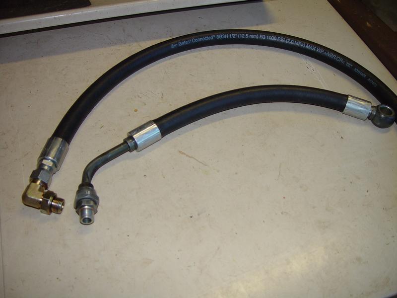
Close up of the newly crimped hose on my reused banjo fittings
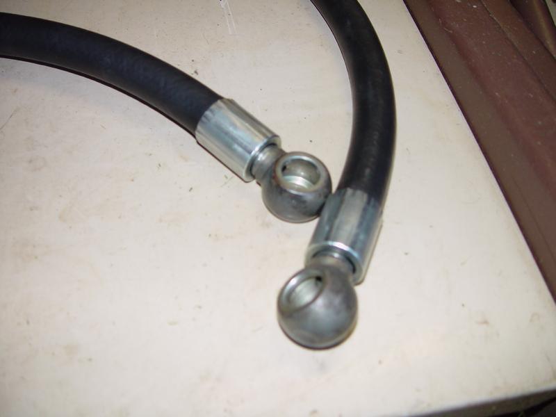
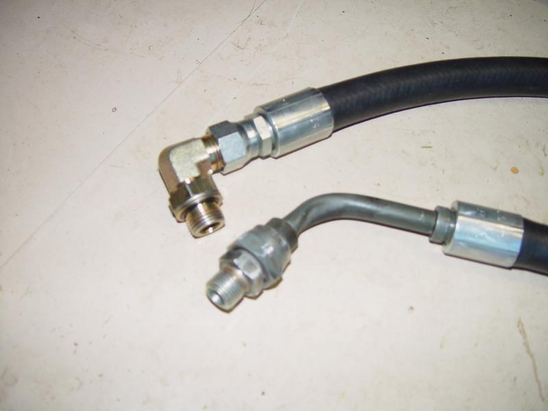
Close up of the newly crimped hose on my reused block fitting and the new swivel 90* fitting:
Hose is rated to 1000psi (that ought to do it) and over 300* (which may be a bit closer to concern, but still plenty of breathing room). They installed quite easily although I did have to turn one of the fittings on the short line a bit to make it line up. The short hose was 13 inches and the long hose was 33 inches. The short one could have stood to be about 1-2 inches longer for slack, although it still fit just right. The long one turned out to be about 2-3 inches on the long side, but as it turned out, the routing worked great so it was fine. I didn't take pictures of them mounted because I'm not sure there was really anything to see. If you're really interested, I'll get some good light in there and snap some pics later...
I think that's it for now -- I welcome questions, comments, etc!
Don't have any pics of the fuel rail, but hopefully the description explains it -- I'll try to get out and take some pics when I have the complete fuel plumbing done.
Also today I went to several hydraulic shops trying to find someone who carried another banjo fitting I could use for my oil cooler lines. I had 2 banjo fittings already that I cut the old hose off of from the oil-cooler ends, but I was hoping to find a banjo fitting for the top of the block too. (FYI the back oil cooler line actually goes to the top of the block under the oil filter on an RE in case you're wondering).
Everywhere I went basically said they'd never seen a banjo that big so I felt like the scrap yard was my only hope. Finally I decided I would do a bit more research and found the thread size of the banjo bolts (18mm x 1.5 pitch). My hope restored, I figured I would be able to find a suitable fitting of that size instead of the banjo. I went back to one of the shops I visited and they had a nice swivel style fitting and a 90* barb. They then clamped on some high pressure high temp hose. He was feeling good and I got out of there for 12 BUCKS!!!!! Yep that's right, I replaced my oil cooler lines for 12 dollars, 12 bucks, 1200 pennies. Needless to say, I was ecstatic since the alternative is to go stainless and approach the $200 mark.
I then went and got raped by OReillys for the copper washers for 2 pairs it was $4.9x with tax. I was in too good of mood to complain much (although I did double check at the Ace close by to see if they were cheaper). But all told, I replaced the whole thing and got them installed tonight. Total price was just under $17 by reusing the 2 banjo fittings on the cooler, the short angle barb on the front of the block and the new swivel 90* fitting on the top (back) of the block.
Here's some pics...
Wide shot of both hoses:
Close up of the newly crimped hose on my reused banjo fittings
Close up of the newly crimped hose on my reused block fitting and the new swivel 90* fitting:
Hose is rated to 1000psi (that ought to do it) and over 300* (which may be a bit closer to concern, but still plenty of breathing room). They installed quite easily although I did have to turn one of the fittings on the short line a bit to make it line up. The short hose was 13 inches and the long hose was 33 inches. The short one could have stood to be about 1-2 inches longer for slack, although it still fit just right. The long one turned out to be about 2-3 inches on the long side, but as it turned out, the routing worked great so it was fine. I didn't take pictures of them mounted because I'm not sure there was really anything to see. If you're really interested, I'll get some good light in there and snap some pics later...
I think that's it for now -- I welcome questions, comments, etc!
05-27-06, 12:44 AM
#116
Eats, Sleeps, Dreams Rotary
OMG what can i say. Words cant describe the beauty that i am seeing. This is the most amazing thing i have ever seen. I would love to do this someday. But i would buy all new OEM stuff from mazda and pretty much build a stock rx7 like if it came out the factory.
But man i give ya mad proops this **** is so friggin hot.
Mad love from New york city
Jason NYC
But man i give ya mad proops this **** is so friggin hot.
Mad love from New york city
Jason NYC

 10-05-06, 03:31 PM
#122
And the Revolution...
Man that was a lot of work and money and time. Just to put all the original stuff back on: Brake lines, Calipers, bushings, Pads and Rotors, shocks, springs.....
Why would you not put new or at least reman stuff on if you're already that far into it? Especially when it comes to the bushings?
Why would you not put new or at least reman stuff on if you're already that far into it? Especially when it comes to the bushings?
10-06-06, 11:46 AM
#123
Rotary Enthusiast
Thread Starter
Join Date: Aug 2002
Location: Kansas
Posts: 1,273
Likes: 0
Received 0 Likes
on
0 Posts
Originally Posted by rx7racerca
Came across this a couple days ago, and finally finished the whole thread. Extremely cool, and great work! How has the car progressed over the summer? I look forward to seeing the final results posted
Thanks for the compliments!
10-06-06, 11:48 AM
#124
Rotary Enthusiast
Thread Starter
Join Date: Aug 2002
Location: Kansas
Posts: 1,273
Likes: 0
Received 0 Likes
on
0 Posts
Originally Posted by DarkKnightFC
Man that was a lot of work and money and time. Just to put all the original stuff back on: Brake lines, Calipers, bushings, Pads and Rotors, shocks, springs.....
Why would you not put new or at least reman stuff on if you're already that far into it? Especially when it comes to the bushings?
Why would you not put new or at least reman stuff on if you're already that far into it? Especially when it comes to the bushings?
And for what it's worth, I'm in it for less money than you might think...