
19 Afr?

Well, one mystery solved!
For User1 I screwed up. Instead of 2F, I'm reading from 2H the Pressure Sensor! 2F is the third from the right on the bottom. I counted that as 3 WIRES but it was 3 HOLES. The second from the right, 2D, is empty! Doh!
So I back-probed the ECU (what a pain in the ***) with the engine hot, the key to On but the engine not running, and I got:
2G - Full Range TPS -
0.75v at idle vs ~0.8v per the FSM
3.73v at full throttle vs ~4.3v per the FSM
2F - Narrow Range TPS -
1.0v at idle vs ~1.0v per the FSM
4.9v at full throttle vs ~5.0v per the FSM
So my Narrow Range looks perfect. The Full Range? I'm not sure if that is in the range of "approximately" or not nor do I know how much the Full Range matters.
Thoughts? I realize this is an S5-specific question.
I went back and checked the JDM Tii TPSs using the resistance procedure on page F2-81.
Full Range TPS
0.10k ohms vs 0.60k ohms to 0.90k ohms in the FSM
5.22k ohms vs 3.40k ohms to 5.10k ohms in the FSM
Narrow Range TPS
0.26k ohms vs 0.8k ohms to 1.2k ohms in the FSM
4.11 ohms vs 4.0k ohms to 6.0k ohms in the FSM
So it's junk.
Full Range TPS
0.10k ohms vs 0.60k ohms to 0.90k ohms in the FSM
5.22k ohms vs 3.40k ohms to 5.10k ohms in the FSM
Narrow Range TPS
0.26k ohms vs 0.8k ohms to 1.2k ohms in the FSM
4.11 ohms vs 4.0k ohms to 6.0k ohms in the FSM
So it's junk.


the WOT TPS values are slightly low, but check the resistance on the full range TPS wires per the FSM diagnostic procedure. I think it says 6 ohms is the max acceptable, but I'm guessing that's with it at .75v volts (throttle closed).
EDIT: I see you just did the test. I would replace the TPS then. They are known to fail.
EDIT: I see you just did the test. I would replace the TPS then. They are known to fail.
Last edited by arghx; Dec 1, 2008 at 08:01 PM.

HAILERS
Joined: May 2001
Posts: 20,563
Likes: 27
From: FORT WORTH, TEXAS,USA
Anytime you probe the ECU, it's easier to unbolt the ECU and then tilt its plugs up where you can acces them easier.
Or pull that particular plug.....backprobe it with a wire........reinstall the plug, then turn the key to ON and observe the meter.
Hey. Have you ever tried this yet??? Pull up the graph and your ......looking at a graph. THEN touch the letter g on the keyboard. NOW you have gauges and numeric figures. Jpgs attached . Hey, I'm easily amused! It might give you some ideas.
And from reading what you wrote above, I see why the USER 1 had jagged lines......boost sensor output. You do have a turbo boost sensor?? or not?
Last edited by HAILERS; Dec 1, 2008 at 09:37 PM.
Yeah, I checked the NAs TPS which is in the car using the Voltage method. The full range may be bad so I'll have to do the ohm test on it but I suspect you're right and I'll need to drop the $300 and get a new tps.
The resistance check I did was was on the TPS that came with the engine from Japan. It hasn't been on the car for several days. But it is obviously bad. It would have been nice if the full range had been good because then I could have Frankensteined a good tps. $300 would go a long way to a new set of shocks! :-)
The resistance check I did was was on the TPS that came with the engine from Japan. It hasn't been on the car for several days. But it is obviously bad. It would have been nice if the full range had been good because then I could have Frankensteined a good tps. $300 would go a long way to a new set of shocks! :-)
Yeah I did unbolt it. Seems like the standard probes are too big for backprobing the ECU.
I found the different display optionswhen I was looking for the ability to define a tranformation formula and axis scale. Sadly doesn't exist. Z still has work to do on the software. Their customer service is great though. I called to find out which pressure sensor to buy and they had a great explanation. I ordered it via the web and it shipped today.
I found the different display optionswhen I was looking for the ability to define a tranformation formula and axis scale. Sadly doesn't exist. Z still has work to do on the software. Their customer service is great though. I called to find out which pressure sensor to buy and they had a great explanation. I ordered it via the web and it shipped today.
HAILERS
Joined: May 2001
Posts: 20,563
Likes: 27
From: FORT WORTH, TEXAS,USA
Just a little FYI. If you ever want to know the starter cranking speed, just disable the fuel pump so no fuel will be delivered, then connect the computer and watch/log the rpms as you crank away.
Now that seems a little screwy, but someday you or someone will do a compression check on the engine, and as everyone knows, to do that right, you SHOULD know the engine cranking rpm. That is one way to do it.
The RTEK2.0 I own does not do that. They don't display rpms until??? heck I forget, but it's not from zero to 300rpm. The only other way I know to do rpm speed is with a good Fluke meter or equiv.
Not looking for a response on this. Just writing at random.
HAILERS
Joined: May 2001
Posts: 20,563
Likes: 27
From: FORT WORTH, TEXAS,USA
The next time you probe the ECU, go to Radio Shack and buy a few Banana jacks and a roll of SINGLE STRAND WIRE and a couple of pieces of Shrink tubing. Then assy a outfit as shown in the attached jpgs. You WANT single strand wire because it's stiffer and there are no *strands* of wire to muck things up.
The single strand 18-22 fits fairly easy into the back of the ECU plug.
The single strand 18-22 fits fairly easy into the back of the ECU plug.
Damn! No wonder you know so much about the electronics on these things. I'm beginning to think your running an N333 simulation in your head... 
Has anyone ever cut one of the TPS sensors in half? I was reading how Dodge, Yamaha and Toyota use rotary style TPS instead of plunger types and it seems that drilling a couple of holes in them and spraying in some Radio Shack cleaner, working them vigorously to clean the corrosion, blowing them out with air and then resealing them with a bit of silicone does the trick. I searched but didnt find anything.
I may grab a hacksaw and get all medieval on one of the JDM TPS sensors that's obviously out of range.
Part of the fun is making what you got work. Anybody Civic-owner can throw new parts at it!
HAILERS
Joined: May 2001
Posts: 20,563
Likes: 27
From: FORT WORTH, TEXAS,USA
If you look at the series five TPS(s), they are both the same outfit (from what I read about it). they can be removed from the TPS bracket. I'm talking the Narrow and Full range sensors on the TPS assy.
Soooooo, if you have one TPS assy with one bad sensor, and yet another with one bad sensor, you should be able to move both GOOD sensors to one TPS assy. Make sense? Say yes.
I don't use the laptop hardly ever. So today I reconnected my EGT to the Zeit and went for a ride. The EGT read just fine and dandy, but the line the EGT is on kept flashing at about 2hz, making me think I had connected it up wrong somehow. Then I realized this(the flashing) is probably part of the WARNING feature. Didn't bother to fix it/adjust it. I'm fairly sure that is what the problem was/is.
Actually I'm a little bit surprised how well the afrs are on that Ethonal/Gas car. No real lean stuff under boost. Just adjusted the RTEK 2.0 to a plus 20.2 more fuel across the board.
Last edited by HAILERS; Dec 2, 2008 at 03:01 PM.
Yeah, I'd read that about the S5 TPSs (NA vs Tii) and so I put the NA's pots on the Tii bracket and that's where we've been since 11/28. The FR on the NA looks spot on but the NR reads from 1v to 4.78v so 0.2v short at WOT. The JDM Tii TPS is a POS on both pots so there is no route to happiness there.
So I ordered a brand new one from Mazdatrix.
Unfortunately, the NR on the Tii TPS was even more out of spec than the NAs so I dont have the pieces to Frankenstein a good TPS.
I did manage to hacksaw the bad NR on the Tii in half. I think you can drill a hole in one of these pots and squirt some Radio Shack pot cleaner (for old tv tuners). I did that to the FR on the Tii TPS but the cleaning juice doesnt dry. Might need diametrically opposed holes so you can move air thru and get it dry inside. So I've ignored it for several days now but I'll look at it again later. I have pictures of the dissected pot which I may post later.
I got the Zeitronix boost sensor and got it installed. I also moved the Z's USER1 lead from the 3rd wire from the bottom right of plug 2 to the 3rd pin and now I have good NR readings being recorded on the Z. It goes from 1v to 4.78v confirming its bad.
Took the car out to pick up sandwiches and I noticed that the close loop mode works very well. It holds to 14.7 AFR with surprising accuracy. There is a very tight wave on the graph while in closed loop.
Still have the hesitation in the 3k range or so. If the new TPS doesnt fix that I'm going to put the 6ohm resisters arghx recommended.
And it still pulses at idle (which is currently 850 rpm) unless I have the lights, heater fan or pretty much any other electrical draw on. Lights off, pulsing idle. Lights on, smooth idle. You'd implied that the reason is obvious but it escapes me.
On the ACV, can I put 12v LEDs in parallel on the solenoids so I can see when they are being told to be on or off? I'm curious to see when they go on and off.
Thanks!
HAILERS
Joined: May 2001
Posts: 20,563
Likes: 27
From: FORT WORTH, TEXAS,USA
Just use the three socket TPS connector to monitor the opening/shutting of the solenoids. Use the LED like the ones in the attached jpg. Try to get two diffeent colors of LED so you can tell which solenoid is coming on, going off.
I assume your just doing this as a temp thing, so just buy a roll of 26ga wire and lengthen the wires coming off the TPS check connetor so it'll reach to the interior.
***NR reads from 1v to 4.78v so 0.2v short at WOT****** I'm not sure the 4.78vdc scares me. What does the narrow range read when you are actually driving the car? I don''t know that much about the series five ECU, but the FSM makes some mention of it being self adjusting???????? So If that is true, then I wouldn't worry about it..
I wonder what that narrow range would read if you put it on the wire for the FULL range and went for drive and pegged the pedal. I bet it would read 99-100 percent at full throttle.
I don't know if you looked at my Zeit graph, but it was reading 99percent and it's voltage isn't five volts when the throttle is pegged.
EDIT: Look at my graph in post #46. That's when I put the narrow range TPS on the USER 1 and had nothing on the TPS for the graph. See how it read 4.80vdc????? Now go look at post #54 where I'd put the narrow range back where it belonged...on TPS...and nothing on the USER 1 (anything you see on USER 1 on that graph is nothing but noise etc, pay no attention to it). Anyway, it reads 100% on TPS for that graph.
Last edited by HAILERS; Dec 7, 2008 at 08:50 PM.
I don't trust the Z's 100% on the trottle read out because I don't think it can "know" what 100% is for that particular TPS. I think that all it can know is where it is relative to the highest voltage it has read so far. I wish they'd allow you to see the raw voltage on it too.
Smoke moar
Joined: Aug 2006
Posts: 2,530
Likes: 1
From: The yay, California
Damn HAILERS your really good at helping, every thread needing real technical help I see ya post`n.
Anyways isn't the s5 tps self adjusting? I have a snap on scanner that will tell you info from the tps it said which plug to connect to, and it just showed up blank, and I thought I read that somewhere.
Anyways isn't the s5 tps self adjusting? I have a snap on scanner that will tell you info from the tps it said which plug to connect to, and it just showed up blank, and I thought I read that somewhere.
Yes, HAILERS is great.
I don't think the TPS is self adjusting, it's just a pair of potentiometers. The ECU must have an algorithm to compensate if the readings are in a reasonable variance of spec.
I don't think the TPS is self adjusting, it's just a pair of potentiometers. The ECU must have an algorithm to compensate if the readings are in a reasonable variance of spec.
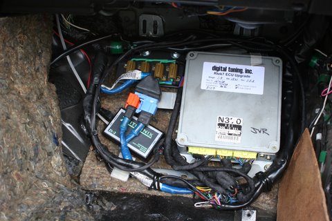
I went ahead and ordered 4 of the 6 ohm resistors as recommended by ARGHX.
^ yes, it's a cheap thing to try. No guarantees, but you're only out like $20. The hesitation and injector response issues become even more apparent when you switch to 1680 secondary injectors.
and they are prettier than the Radio Shack ones too! 
Allied Electronic's main warehouse appears to be in Ft Worth so they should be here tomorrow. And the new TPS from Trix arrives Thursday. Hopefully between that combined $350 the 3k to 4k surging goes away and the idle smooths out without having to turn the lights on!
The kid comes back from college on the 18th so my goal is to have it ready for tuning runs before then. Since its a new build I'm limiting the Rs to 4500 or so but that will be good practice.
We'll be back in the upper 60's this weekend so I'm crossing my fingers everything goes well. We're dropping from the mid-70s today to only the 50's tomorrow and Im not much for working on the car with cold fingers. Makes the inevitable finger jams all the worse. On the other hand, it slows down the bleeding...
Last edited by vrracing; Dec 9, 2008 at 07:19 AM.
Got the 6ohmers installed today. Sadly, it made no difference. Still have the stumbling between 3 and 4k. I also changed the Zeitronix to draw power from the cigarette lighter power source but that didnt help either.
So, next thing will be to install the new TPS.
So, next thing will be to install the new TPS.
What Does A $350 Tps Get You?
A beautiful, smooth idle with no bouncing idle whether the lights are on or off! 
I hereby decree that whenever someone buys an FC they have to buy a brand new TPS as a prerequisite for posting!
Set the idle to right around 750. NR is right at exactly 1.0v.
 But we still have the surging between 3-4k.
The funny thing is I'm not sure that it doesnt match the rhythm of closed loop. You can feel those humps you see in the AFR.
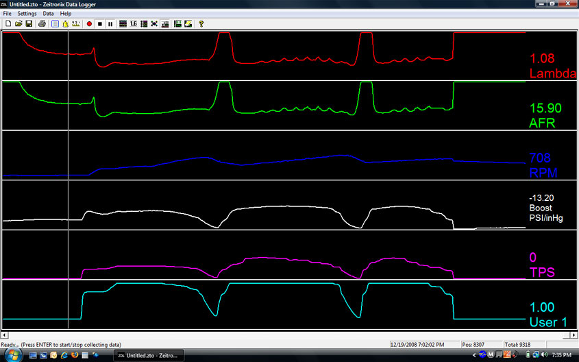
Here's the Zeitronix file. The part in the picture above is at the end.
vr surging.zip
And I'm running the 6ohm injector resistors as shown here.
Any ideas? The AFRs all look pretty much in range now that the TPS is rockin'.
The only thing that isn't connected is the turbo duty solenoid. It was buzzing before I put the new TPS in so I disconnected the plug. But as you can see the boost never get more than 5psi.
So in brief, it seems to accelerate nice to 3k, hump to 4k, then smooth out nice after 4k to 5.5k. We havent exceeded 5.5k because it's still a newly rebuilt engine.
Thanks for any insight.
Jim
I hereby decree that whenever someone buys an FC they have to buy a brand new TPS as a prerequisite for posting!
Set the idle to right around 750. NR is right at exactly 1.0v.
The funny thing is I'm not sure that it doesnt match the rhythm of closed loop. You can feel those humps you see in the AFR.
Here's the Zeitronix file. The part in the picture above is at the end.
vr surging.zip
And I'm running the 6ohm injector resistors as shown here.
Any ideas? The AFRs all look pretty much in range now that the TPS is rockin'.
The only thing that isn't connected is the turbo duty solenoid. It was buzzing before I put the new TPS in so I disconnected the plug. But as you can see the boost never get more than 5psi.
So in brief, it seems to accelerate nice to 3k, hump to 4k, then smooth out nice after 4k to 5.5k. We havent exceeded 5.5k because it's still a newly rebuilt engine.
Thanks for any insight.
Jim
HAILERS
Joined: May 2001
Posts: 20,563
Likes: 27
From: FORT WORTH, TEXAS,USA
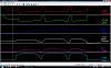
In the jpg I attached, your boosting to 3-4psi and the afr is in the 14.7 range give or take.
That's pretty lean for boosting I think. I don't think it's possible to be boosting and be in closed loop. Pretty darn sure. I've no idea why it's lean like that with a stock ECU.
The second jpg is you cruising along in closed loop. That's pretty natural looking to me.
Have you made any adjustments with the SAFC? to have caused the lean when boosting?
Were you driving at night when doing this?
Fuel pump not up to speed?
Last edited by HAILERS; Dec 19, 2008 at 08:48 PM.
HAILERS
Joined: May 2001
Posts: 20,563
Likes: 27
From: FORT WORTH, TEXAS,USA
It's odd. The first jpg is but moments before the second jpg. The first one has afr in the 13's and the second one starts doing that up/down bs and is in the 14's and you'd almost swear it's in closed loop. I say you can't go closed loop in boost or acceleration.
To prove it, just remove the 02 sensors connector and ape the run you did in this post.
No. I don't know what's wrong.
To prove it, just remove the 02 sensors connector and ape the run you did in this post.
No. I don't know what's wrong.
HAILERS
Joined: May 2001
Posts: 20,563
Likes: 27
From: FORT WORTH, TEXAS,USA
I don't remember much about this jpg. It was in the file. Just showing that at five psi mine looks NOT like yours.
The USERS is NOT a TPS voltage. I forget what it is. This is a series four car.
The USERS is NOT a TPS voltage. I forget what it is. This is a series four car.