
19 Afr?

19 Afr?
90 vert with rebuilt and Pineapple templated JDM Tii with appropriately modded NA harness. Zeitronix w/b sensor at the front of the midpipe near the downpipe.
I'm reading 18-19 AFM on the Zeitronix at idle. That seems like it would have gone boom if a real number.
I found a post from Karack from a few years back saying that we should be at 11:1 AFR. With the ACV and all other emissions fully operational, should we still see 11s?
I think the narrow range TPS is bad (see other thread) so I'm swapping that out now with the one from my NA.

HAILERS
Joined: May 2001
Posts: 20,563
Likes: 27
From: FORT WORTH, TEXAS,USA
IF the ACV and airpump are working, then that figure is not abnormal.
If this was a stock turbo car, fully functional, then if the vacuum hose on the ACV that sticks straight UP is removed and plugged with a small bolt, then the afr numbers will fall to the 13's.
IF the airpump and ACV are not operational, then somethings funny here.
If this was a stock turbo car, fully functional, then if the vacuum hose on the ACV that sticks straight UP is removed and plugged with a small bolt, then the afr numbers will fall to the 13's.
IF the airpump and ACV are not operational, then somethings funny here.
Thank you HAILERS & Roen for confirming that the 19AFR was not out of whack and the engine was at the edge of destruction!
Ok, car specs first
1990 Vert
Ok, we made progress with the NA's TPS moved over to the Tii bracket. Got the single LED lit.
I've attached the ZTO file from the Zeitronix (zipped of course) from our test run.
High AFR.zip
It idles at 850 and the narrow range is reading 1.20v. Both too high but the LED was lit and it is a new rebuild.
What's weird (though not illustrated in the ZTO) is that the idles bounces a little. But if we turn the lights on, it smooths right out. btw, the lights were on during the entire span of the ZTO.
If I plug the ISC in, nothing obvious happens. If I unplug the BAC, nothing obvious happens.
Note that on the ZTO we dont have the boost or EGT so they can be ignored or turned off.
At 5:47pm (scroll the horizontal scroll bar) you can see that the we accelerated from a stop. What's odd is that the car surges during acceleration and as you can see the AFR surges as well. The AFR was at about 15 if you average out the surges.
At 5:48:50 we got it over 3.8k RPM. You can see that as the 1000cc secondaries kicked in, that the AFR smoothed right out, surging went away and the AFR dropped a ton to about 10.9 AFR.
So with all the emissions intact and functional, what AFR are we looking for? I'm guessing Karack's 11.0 target was for a de-emissioned car. And should I cap the vertical port on the ACV while tuning?
Thanks!
Jim
Ok, car specs first
1990 Vert
- JDM S5 Tii swap including manual tranny
- NA harness with appropriate mods
- Intake and Exhaust ported with Pineapple templates
- All emissions intact
- All vacuum hoses replaced
- RTek 1.8 (720cc target injectors for both)
- Primaries new 720cc GReddys from RETed
- Secondaries new 1000cc RCs
- 10ohm resistors at the ECU
- SAFC Neo - no adjustments made to date
- Zeitronix w/b AFM
- Stock intake
- RP downpipe, midpipe (modded for w/b sensor) and Bonez cat
- Corksport catback
Ok, we made progress with the NA's TPS moved over to the Tii bracket. Got the single LED lit.
I've attached the ZTO file from the Zeitronix (zipped of course) from our test run.
High AFR.zip
It idles at 850 and the narrow range is reading 1.20v. Both too high but the LED was lit and it is a new rebuild.
What's weird (though not illustrated in the ZTO) is that the idles bounces a little. But if we turn the lights on, it smooths right out. btw, the lights were on during the entire span of the ZTO.
If I plug the ISC in, nothing obvious happens. If I unplug the BAC, nothing obvious happens.
Note that on the ZTO we dont have the boost or EGT so they can be ignored or turned off.
At 5:47pm (scroll the horizontal scroll bar) you can see that the we accelerated from a stop. What's odd is that the car surges during acceleration and as you can see the AFR surges as well. The AFR was at about 15 if you average out the surges.
At 5:48:50 we got it over 3.8k RPM. You can see that as the 1000cc secondaries kicked in, that the AFR smoothed right out, surging went away and the AFR dropped a ton to about 10.9 AFR.
So with all the emissions intact and functional, what AFR are we looking for? I'm guessing Karack's 11.0 target was for a de-emissioned car. And should I cap the vertical port on the ACV while tuning?
Thanks!
Jim
Last edited by vrracing; Nov 28, 2008 at 06:56 PM.
HAILERS
Joined: May 2001
Posts: 20,563
Likes: 27
From: FORT WORTH, TEXAS,USA
If you have a catalytic converter, you should replace that vertical vacuum hose pretty soon after doing runs/whatever. If you have no converter, it matters not if that Switching vacuum hose is off and plugged.
Remember the 02 sensor will still effect the steady speed driving. You might just pull its plug off and see if you notice anything different.
I'm no tuner (had a father and it's on my birth certificate), but 10 and under just cause BOGGING as far as I'm concerned. I've no heartburn seeing 12's when getting on it. Others might have different opinions on it.
IN general the BAC won't respond if the engine speed is over 750rpm. Take that into account.
I realized that most folks dont have the Zeitronix software so couldn't see my logs. Here's a png of part of the run.
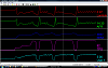
You can see that the car is idling, then goes into first, second, third and fourth.
User 1 is the voltage from the narrow band TPS. It should be 1v at idle but we're 1.20v. But the LED was on. /sigh Anyone else hate the TPS?
In the AFR band you can see that below 3600rpm (the switchover to the secondaries with the RTek1.8) the line bounces and the car surges at it accelerates. I have no idea why. The AFR is "lean" bouncing between 14 and 15 but I dont know if the ACV is involved in this or not. Once it gets to 3600, the acceleration smooths right out.
Tomorrow we're going to do a couple of runs to tune the AFR using the SAFC. Here's my plan which is based on this thread and this thread.
Target will be 13 AFR across the board.
We'll unplug the blue solenoid so that the air pump doesnt distort the readings.
Lo and Hi throttle maps will be at 30% and 80% respectively.
We'll make a pass at 30% throttle and adjust the 30% map
Repeat until we have consistent 13 AFR
Repeat for 80% throttle.
Plug the blue solenoid back in so I dont ruin my cat.
What do yall think?
Thanks,
Jim
Last edited by vrracing; Nov 28, 2008 at 09:22 PM.
HAILERS
Joined: May 2001
Posts: 20,563
Likes: 27
From: FORT WORTH, TEXAS,USA
Things like this are not good. At 3800rpm, I guarantee the Relief solenoid should have been de-energized and the air pressure should have opened the relief valve in the ACV and the air dumped overboard.
In this jpg attached your over 3800rpm and the afr is waaaay up there where it shouldn't be. But you know that.
Pulling the Blue plug off should route air pressure thru the Relief solenoid to the relief valve in the ACV and it should be dumping air overboard all the time. So if you get the same results as the jpg attached, then the fuel is just flat lean.
Personally I'd adjust the narrow to one volt at idle with hot engine. I don't think it has much of anything to do with the high afr's.
Last edited by HAILERS; Nov 28, 2008 at 11:44 PM.
Trending Topics
HAILERS
Joined: May 2001
Posts: 20,563
Likes: 27
From: FORT WORTH, TEXAS,USA
Some of this makes me WONDER if your ACV is good or bad or if the hose to it are in the right places. There's just too much in the lean too much of the time.
I'd pull that large hose on the side off and rev the engine over 3800 and make sure that air is being dumped for sure out the side.
Or idling hot, you should be able to just remove that hose that is sticking up and when you do that, the air should come out the side of the ACV.
Or an oddball way to make it relieve all the time, is to find the nipple on the ACV that airpump air comes out (the one sticking out towards the fender) and route the other end of that hose to the nipple on the mushroom outfit on the bottom of the ACV. Do that and air should blow out the large nipple on the side of the ACV all the time. And nowhere else. The afr at idle should also drop down in the 13's when you do that.
ON a turbo car, with a fully functioning ACV, hot engine, should read lean at idle.
When you take off in first or second gear, you can slowly accelerate to 15mph. Around that speed the afr should now read leaner as in the 14.7-15.2 range, from the 19?afr you saw at idle, because the switching solenoid gets energized when you advance the pedal, and as you slowly accelerate to 25mph it should still read that figure.
If you try to hold 25mph on a level or slightly downhill grade, the afr might go back to the lean figure you saw at idle. That's becaue you will probably let off the pedal (can you say TPS) and the Switching solenoid will de-energize, making all the air go to the exhaust ports.
When the Switching solenoid is energized and the relief solenoid is still energized, SOME of the air will bleed off into the split air pipe (switching valve opened the path to the split air pipe). So now you don't have as much air going to the exhaust ports and hence the afr will go richer.
As you know, the TPS controls when the Relief and Switching solenoids open/shut plus some other factors like rpm.
I really shouldn't have written any of that about the ACV. I wrote it in a disjointed way and I'm too lazy to rewrite it.
A series four ACV's vacuum hose are routed as in the attached jpgs. Route F to G in the jpg and the air gets dumped all the time.
Last edited by HAILERS; Nov 29, 2008 at 12:16 AM.


I've done my share of tuning with SAFC's and standalones, and when I look through that chart you posted, Nothing really sticks out to at me as a significant problem.
Your narrow range TPS is in spec, or at least, it's close enough. The spec for an FD narrow range TPS is .75-1.25 volts according to the FD FSM, and the FD TPS is effectively the same as the s5, which is why they are both compatible with the Power FC. I suppose it wouldn't hurt to adjust it down some, but I wouldn't expect it to make a big difference. Your AFR curve is pretty much where I would expect it to be. It is superlearn at idle due to the airpump, then it oscillates under low load driving because it is in closed loop. That's how closed loop control works--constantly self-correcting to reach a target value, in this case 14.7:1 AFR or lambda 1.0 . Your car is going superlean when you let off the gas, as it should be. It MIGHT have a slight tip-in problem off idle, but your logs are inconclusive on that. I don't see the surging you speak of. I guess I would have to drive the car to know for sure if it needs anything.
So what is the complaint exactly? Why do you want 13 AFR across the board again? You might want 13 AFR at idle, but you will need to disable the airpump and adjust your variable resistor for that.
In fact, you need to 100% disable the ACV/airpump's effect on the exhaust stream (by whatever method you choose) before attempting tuning. You only need them for an emissions test. Get the car running fine without that stuff and then plug it back in ater. Your cat will survive long enough without an airpump that you shouldn't even worry about it.
Your SAFC is useless for anything but WOT or near-WOT tuning, especially since you are trying to pass emissions and thus your O2 sensor needs to be fully functional.. It doesn't matter that much what you set your throttle points at. Under low load it is going to run in closed loop and ignore your corrections, although you can play around with the idle AFR a bit.
Last edited by arghx; Nov 29, 2008 at 01:05 AM.
HAILERS
Joined: May 2001
Posts: 20,563
Likes: 27
From: FORT WORTH, TEXAS,USA
See the attached jpg. See the red arrow. The TPS is pegged out and he has afr of 15afr something or other.
02 isn't in closed loop at a TPS in the nintys or if the rpm is over 3500rpm.
I wish you'd swap the narrow and full range TPS wires on the Zeitronix. It might be messing with my mind, but if the Full range is in the nintys, then it's a given the narrow range is 100% for sure.
I've never looked at narrow range voltages with the pedal pegged out (driving), but I'd expect something in the 4.5vdc to 5vdc instead of the anemic 3vdc I see a lot of on the graph. Then I don't have a series five TPS either. Then maybe the USER is NOT the narrow range and you've swapped the wires already? Still.....
Last edited by HAILERS; Nov 29, 2008 at 11:10 AM.
Woah! That's a lot of info!
On the full vs narrow range, I have both the Zeitronix and SAFC TPS wires on 2G which on an S5 is the full range as specified in the SAFC documentation. The Zeitronix User1 is hooked to 2F which on the S5 is the narrow range.
I need to go pick up a new DMM. I bought batteries for the old one but it still didnt work. Then I'll warm it up and then run the throttle up and down and get the volt range from back-porting pins 2F and 2G.
The RTek 1.8 is preconfigured for 720cc injectors. So in theory below 3600rpm (the switchover on the RTek) we should be pretty close to a decent tune. But with the 1000cc injectors in the secondaries, we should be grossly rich above that.
Yet, we are always lean so the ACV is a consistent theme. I'll take a photo of the ACV so we can verify the hoses. On the vacuum diagram in the FSM all of the lines disappear behind the UIM because of the angle of the drawing. It all looks logical the way I've set it up but you never know.
The ACV reminds me of something else. There is a buzzing noise coming from the area of the solenoids. It starts and stops when I'm adjusting the TPS. I'll get the stethescope and figure out which one it is. I went thru them all with the FSM check procedures but maybe something else is going on.
Oh and why 13 AFR? Because I have to compensate for the 1000cc injectors (25% rich?) and I need a number to shoot for and as noted in the previous links, 13 seems to be a reasonable number. My original plan was to match what the RTek guys set it for below 3600 but since that number bounces up and down there doesnt seem to be any point.
Thanks again for all the help.
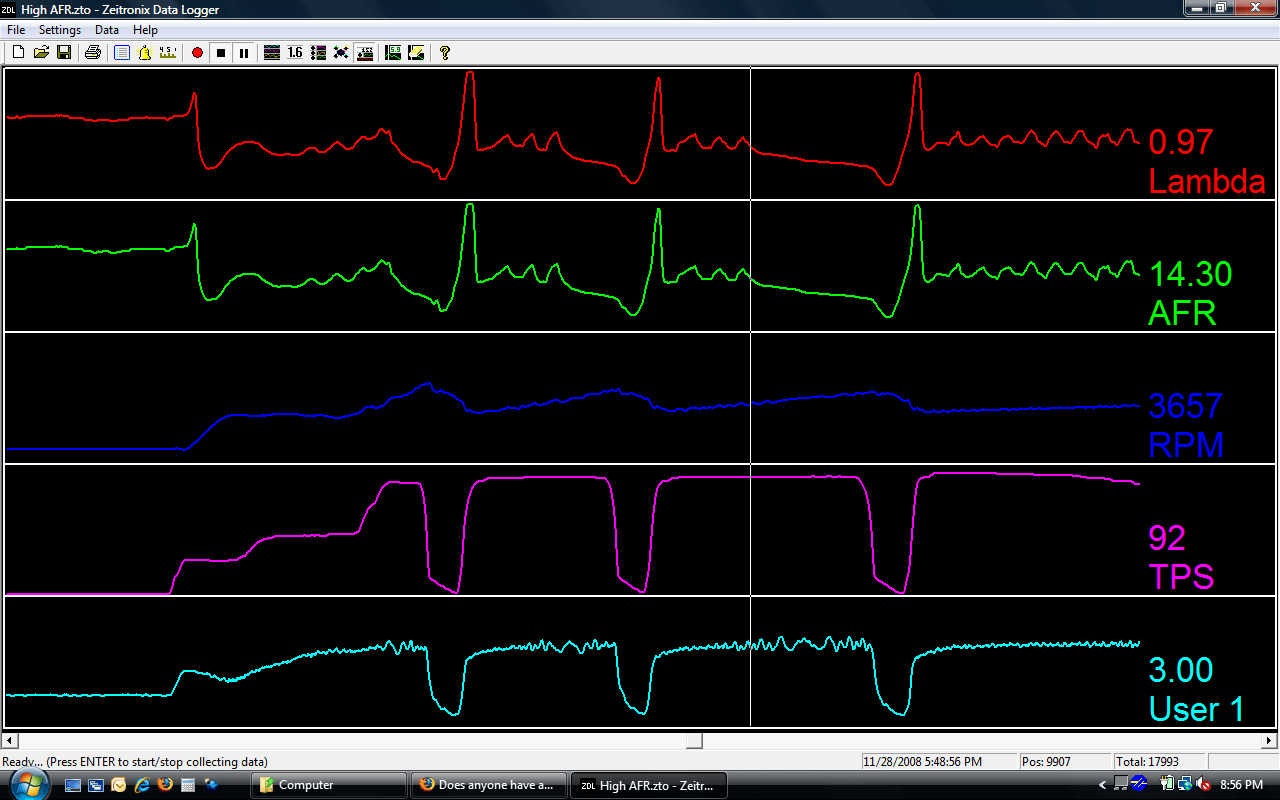
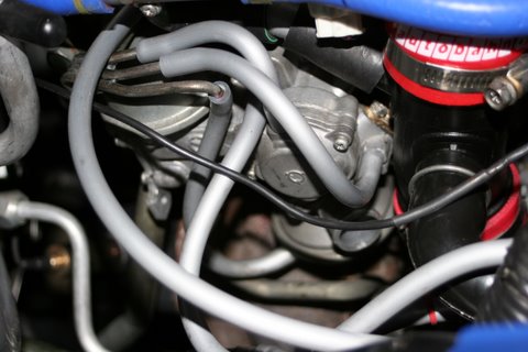
ACV Plumbing
Here are the pics of the ACV and the solenoids though you can't see much of the solenoids because of the TMIC bracket.
btw, I have no CEL codes.
btw/btw, could it be that the SAFC and Zeitronix together are pulling down the volts on the TPS, hence the maxing out at 3v on the narrow range?
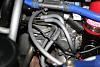
Oh, the dump port isnt hooked up and hasnt been because the hose is for the NA and doesnt quite reach the Tii's ACV.
Eating turkey sandwich and then off to get a new DMM.
btw, I have no CEL codes.
btw/btw, could it be that the SAFC and Zeitronix together are pulling down the volts on the TPS, hence the maxing out at 3v on the narrow range?


Oh, the dump port isnt hooked up and hasnt been because the hose is for the NA and doesnt quite reach the Tii's ACV.
Eating turkey sandwich and then off to get a new DMM.
Last edited by vrracing; Nov 29, 2008 at 12:53 PM.
looking through the 3 pics hailers posted, something is definitely up with your TPS. you should have narrow range voltage around 4.7-4.9 with the pedal like halfway down (full range TPS like 2.5-3.0 volts).
Your lean spot is at the injector transition. What resistors are you using for your secondarys? The 10 watt/10 ohm have been known to give people trouble with lean spots. I would use no more than 6 ohm, which is the factory resistor pack for the 87 models, and is in fact what I use on my car with 1680 secondarys. In fact, i had lean spots on my old Rtek 1.7 until I switched to 6 ohm resistors.
If you can't get at least 4.5-4.7 volts WOT out of your narrow range TPS after adjusting it, you probably have a bad TPS. The narrow range TPS is used to control emissions solenoids, so that could explain part of the problem. One more thing: you do have a later model Rtek with the stumble elimination fix right?
Last edited by arghx; Nov 29, 2008 at 01:42 PM.
Yeah, I have 10 ohms 10 watts as recommended by as I recall Aaron.
I'd mentioned that the idle smoothed out when turning on the lights. I was watching the full range tps on the Z and noticed that when I turned on the heater fan, the volts at idle dropped from 1.2 to 1.1v. So the TPS is the focus for the moment.
I'd mentioned that the idle smoothed out when turning on the lights. I was watching the full range tps on the Z and noticed that when I turned on the heater fan, the volts at idle dropped from 1.2 to 1.1v. So the TPS is the focus for the moment.
Oh yes, I have the latest RTek 1.8 for the S5 Tii.
I got it warm and set the TPS using what I believe is HAILERS' preferred method of adjusting for 1.0v from the green/red wire at the TPS while the car is running at idle as described here. I started at .95v and screwed it in until it read 1.0v.
Here's a pic...

Sadly, no change.
I got it warm and set the TPS using what I believe is HAILERS' preferred method of adjusting for 1.0v from the green/red wire at the TPS while the car is running at idle as described here. I started at .95v and screwed it in until it read 1.0v.
Here's a pic...
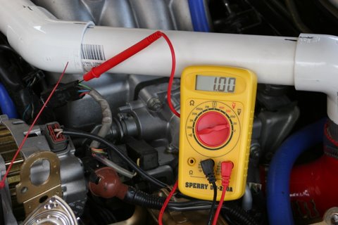
Sadly, no change.
The buzzing
The buzzing was coming from the Duty Solenoid. I found it with the stethoscope and confirmed it by unplugging it. It would buzz at different settings of the TPS but I couldnt see a pattern.
I doubt this is affecting the idle and AFRs though. I'll trace the vacuum lines later to be sure and I'll do the pinout checks from the FSM as well.
I doubt this is affecting the idle and AFRs though. I'll trace the vacuum lines later to be sure and I'll do the pinout checks from the FSM as well.
HAILERS
Joined: May 2001
Posts: 20,563
Likes: 27
From: FORT WORTH, TEXAS,USA
Yeah, I have 10 ohms 10 watts as recommended by as I recall Aaron.
I'd mentioned that the idle smoothed out when turning on the lights. I was watching the full range tps on the Z and noticed that when I turned on the heater fan, the volts at idle dropped from 1.2 to 1.1v. So the TPS is the focus for the moment.
I'd mentioned that the idle smoothed out when turning on the lights. I was watching the full range tps on the Z and noticed that when I turned on the heater fan, the volts at idle dropped from 1.2 to 1.1v. So the TPS is the focus for the moment.
When you turned on the lights etc, the BAC should have seen this and added AIR or upped it's duty cycle if you will. It bypassed more air to the intake. That give you any clues?
Just as an aside, I was monkeying around on one of my cars this day. Pretty cold day at that. I had the key to ON,engine off. Now I know what the buzzing of the bac duty cycle is, so when I heard a little man in my engine tapping out Morse Code, I thought it was a relay gone askew. Nope, it was the Switching solenoid going clickity click. Seems with the cold engine and watertherowax holding the throttle linkage open, the TPS on the other end of the throttle shaft was just on the verge of causing the ECU to put a gnd on the Switching solenoid. Therefore the clickity clickity click. humor
HAILERS
Joined: May 2001
Posts: 20,563
Likes: 27
From: FORT WORTH, TEXAS,USA
*****The ACV reminds me of something else. There is a buzzing noise coming from the area of the solenoids. It starts and stops when I'm adjusting the TPS.********************************************** ***********
Your hearing the Switching and or the Relief solenoids pulling in/out. When you set the TPS, what your doing is also setting up the Relief and Switching solenoids.
When the TPS output approx (APPROX) one volt dc, that one volt goes to the ECU and the ECU sees that, and that tells the ECU to put a ground on the Relief Solenoid. Or energize it if you will. The Relief solenoid always has batt voltage on its black/white wire, and all it's looking for is a ground output from the ECU. That happens if the TPS outputs approx one volt dc.
Look at the TPS check connector. One wire is black/white and is there to power up the LED'S. Then one of the other wires in that TPS check connector is the same color as one of the wires on the Switching solenoid and the other wire on the TPS check connector is the same color as one of the two wires on the Relief solenoid.
So the ECU sees output of one volt approx from the TPS itself, so it then puts a gnd on the Relief solenoid to energize it.
When the TPS is set right, the Relief solenoid will be energized (one light on thing with the LED's), and the Switching solenoid won't be energized (the one light off thing with the LED's).
That is one of the functions of the TPS.
Last edited by HAILERS; Nov 29, 2008 at 05:43 PM.
HAILERS
Joined: May 2001
Posts: 20,563
Likes: 27
From: FORT WORTH, TEXAS,USA
One thing that won't take much effort and time, is to get out a 12mm wrench and remove the airpumps belt. Then go for a log/drive and see if the afrs are the same as before removing the belt. One or two runs won't kill the converter.
And approx is approx. On my series four a 0.95 or a 1.10 work just as well as one volt dc. For me at least. But I always put it at one volt. Nice figure. A little here, and a little there won't be reactionary.
And approx is approx. On my series four a 0.95 or a 1.10 work just as well as one volt dc. For me at least. But I always put it at one volt. Nice figure. A little here, and a little there won't be reactionary.
Last edited by HAILERS; Nov 29, 2008 at 05:47 PM.
HAILERS
Joined: May 2001
Posts: 20,563
Likes: 27
From: FORT WORTH, TEXAS,USA
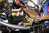
See the jpg attached. I called one place A and the other B. IF you take the hose on A, and leave that end on A, but then pull the other end of that hose off and put it on B, then the relief big *** nipple will relieve air all the time.
Try that. Just put the other end of A on B and idle a hot engine. Feel the air coming out the big nipple dumping air overboard. Rev the engine and the air volume picks up and at all engine speeds still dumps air overboard. Now go for a run and see what happens to the afr.
Your hoses do seem to be connected up right on the ACV. Can't say if the other ends are right or not.
You might disconnect the SAFC and see how that effects things if at all. Like unplug it only. Leave any soldered on wiring in place.
OH. One more thing. Do you know when that RTEK device turns on the secondarys? Stock is 3800rpm approx.
Last edited by HAILERS; Nov 29, 2008 at 06:19 PM.
************************************************** ************************************************** ***************************
When you turned on the lights etc, the BAC should have seen this and added AIR or upped it's duty cycle if you will. It bypassed more air to the intake. That give you any clues?
When you turned on the lights etc, the BAC should have seen this and added AIR or upped it's duty cycle if you will. It bypassed more air to the intake. That give you any clues?
*****The ACV reminds me of something else. There is a buzzing noise coming from the area of the solenoids. It starts and stops when I'm adjusting the TPS.********************************************** ***********
Your hearing the Switching and or the Relief solenoids pulling in/out. When you set the TPS, what your doing is also setting up the Relief and Switching solenoids.
Your hearing the Switching and or the Relief solenoids pulling in/out. When you set the TPS, what your doing is also setting up the Relief and Switching solenoids.
Originally Posted by HAILERS
When the TPS is set right, the Relief solenoid will be energized (one light on thing with the LED's), and the Switching solenoid won't be energized (the one light off thing with the LED's).
That is one of the functions of the TPS.
One thing that won't take much effort and time, is to get out a 12mm wrench and remove the airpumps belt. Then go for a log/drive and see if the afrs are the same as before removing the belt. One or two runs won't kill the converter.
And approx is approx. On my series four a 0.95 or a 1.10 work just as well as one volt dc. For me at least. But I always put it at one volt. Nice figure. A little here, and a little there won't be reactionary.
And approx is approx. On my series four a 0.95 or a 1.10 work just as well as one volt dc. For me at least. But I always put it at one volt. Nice figure. A little here, and a little there won't be reactionary.
See the jpg attached. I called one place A and the other B. IF you take the hose on A, and leave that end on A, but then pull the other end of that hose off and put it on B, then the relief big *** nipple will relieve air all the time.
Try that. Just put the other end of A on B and idle a hot engine. Feel the air coming out the big nipple dumping air overboard. Rev the engine and the air volume picks up and at all engine speeds still dumps air overboard. Now go for a run and see what happens to the afr.
Try that. Just put the other end of A on B and idle a hot engine. Feel the air coming out the big nipple dumping air overboard. Rev the engine and the air volume picks up and at all engine speeds still dumps air overboard. Now go for a run and see what happens to the afr.

I was thinking of pulling the Zeitronix out too but I need to reread the instructions as I remember that there is something about it having a heater which if I unplug it wont get heated. That might be bad.

Thanks again, it's been very educational!
Last edited by vrracing; Nov 29, 2008 at 08:45 PM.
looking through the 3 pics hailers posted, something is definitely up with your TPS. you should have narrow range voltage around 4.7-4.9 with the pedal like halfway down (full range TPS like 2.5-3.0 volts).
If you can't get at least 4.5-4.7 volts WOT out of your narrow range TPS after adjusting it, you probably have a bad TPS. The narrow range TPS is used to control emissions solenoids, so that could explain part of the problem. One more thing: you do have a later model Rtek with the stumble elimination fix right?
If you can't get at least 4.5-4.7 volts WOT out of your narrow range TPS after adjusting it, you probably have a bad TPS. The narrow range TPS is used to control emissions solenoids, so that could explain part of the problem. One more thing: you do have a later model Rtek with the stumble elimination fix right?
Thanks, arghx. It's a good idea to verify my assumption.