
Various vac lines on 20B?


Thread Starter
Rotary Enthusiast
Joined: Aug 2008
Posts: 1,101
Likes: 13
From: Portsmouth UK
Various vac lines on 20B?
Okay,
So I have a donor engine to go in my car and some of the vac lines are off or moved around and with taking out left over hard pipes from the rat nest I want to be sure I connect it back up right.
Please can someone confirm the following.
The oil injector vacuum lines need to be plumbed in pre-turbo? I.e to the turbo compressor housing?
It is considered best to have the vacuum line for the fuel pressure regulator feeding from the centre of the LIM?
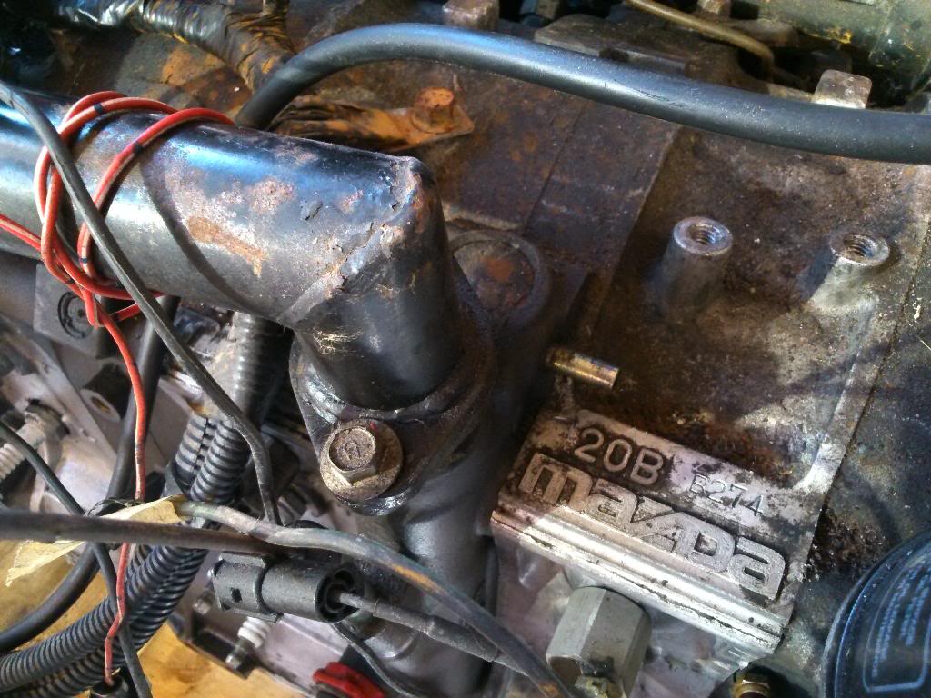
Should the oil breather stub (assume that is what the below pipe is behind the filler kneck)
be connected pre-turbo as well ideally with a one way valve in it?
Thank you
Lee
So I have a donor engine to go in my car and some of the vac lines are off or moved around and with taking out left over hard pipes from the rat nest I want to be sure I connect it back up right.
Please can someone confirm the following.
The oil injector vacuum lines need to be plumbed in pre-turbo? I.e to the turbo compressor housing?
It is considered best to have the vacuum line for the fuel pressure regulator feeding from the centre of the LIM?
Should the oil breather stub (assume that is what the below pipe is behind the filler kneck)
be connected pre-turbo as well ideally with a one way valve in it?

Thank you
Lee

Thread Starter
Rotary Enthusiast
Joined: Aug 2008
Posts: 1,101
Likes: 13
From: Portsmouth UK
That might help although I am going single turbo and have no Ratsnest so I want to be sure what I do with pipes when they no longer pass through a solenoid.
I did this all a long while ago on my 13B and I think what I have suggested I my first post is correct. I just need confirmation.
Thank you
Lee
I did this all a long while ago on my 13B and I think what I have suggested I my first post is correct. I just need confirmation.
Thank you
Lee
In the stock configuration, the Middle Iron Nipple, AKA the BlowBy port, gets plumbed back into the UIM via the Purge Valve. Putting a Catch Can on this line seems like a wise idea to keep the UIM & LIM from getting all gunked up inside.
Thread Starter
Rotary Enthusiast
Joined: Aug 2008
Posts: 1,101
Likes: 13
From: Portsmouth UK
Hi There,
Did you post your translated diagram? If so can you post a link to it please?
If you connect to the UIM then you would only get suction when the throttle is closed? I think the 13B does the same via a one way valve if I recall correctly.
If you plumb the breather via a catch can to the turbo inlet then you have permanent suction. I am not sure how much of an issue with breathing rotaries have?
Thanks for the info.
Lee

Thread
Thread Starter
Forum
Replies
Last Post
Jeff20B
1st Generation Specific (1979-1985)
73
Sep 16, 2018 07:16 PM
rx7jocke
Suspension/Wheels/Tires/Brakes
72
Jun 17, 2016 03:48 AM
Nosferatu
2nd Generation Specific (1986-1992)
7
Sep 5, 2015 02:13 PM