
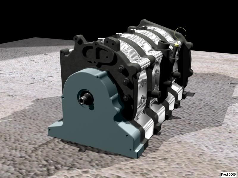
3D CAD Model *pics inside*


Thread Starter
I may be wrong
Joined: Sep 2005
Posts: 17
Likes: 0
From: Redwood Valley, Ca
What do ya'll think about this doosey? Now whether or not it would hit is another issue, but this is the basic design. I think it looks ugly, but was wondering if it would work?
Last edited by swimmer4uus; Aug 28, 2006 at 01:33 AM.
Originally Posted by Steel
er uh... arent 20b rotors NOT 120 out of phase? I thought two of them were in the same phase and the third one was 180 out from that?
I'm your huckleberry..
Joined: Jul 2002
Posts: 736
Likes: 0
From: Tucson, AZ
Originally Posted by GtoRx7
No, they are exactly 120 degrees from each other. The two rotor is 180 degrees.
Originally Posted by Steel
shadamn. i could have SWORN that the two rotors that are closer to each other were in teh same phase and the third one was 180 out. Where could i have gotten this idea? I thought that's what explained the 20b's funny sounding exhaust note.
I'm your huckleberry..
Joined: Jul 2002
Posts: 736
Likes: 0
From: Tucson, AZ
Well i can imagine the 120 phase no problem. this is how i first thought of these motors until i read, or someone told me otherwise. buuut. i guess they were wrong.
my whole world has come crashing down.
Anyone know what the firing order for the 26B motor is? maybe i was thinking of that one.
my whole world has come crashing down.
Anyone know what the firing order for the 26B motor is? maybe i was thinking of that one.
Originally Posted by Steel
Well i can imagine the 120 phase no problem. this is how i first thought of these motors until i read, or someone told me otherwise. buuut. i guess they were wrong.
my whole world has come crashing down.
Anyone know what the firing order for the 26B motor is? maybe i was thinking of that one.
my whole world has come crashing down.
Anyone know what the firing order for the 26B motor is? maybe i was thinking of that one.


Senior Member
Joined: Aug 2003
Posts: 703
Likes: 0
From: Moon Twp. Pennsylvania
I posted a 3-d model of my intake manifold for all to see if interested in my thread.
Check it out and subscibe if you are not already as i am getting ready to start posting some really cool updates again.
https://www.rx7club.com/showthread.p...&page=46&pp=15
Check it out and subscibe if you are not already as i am getting ready to start posting some really cool updates again.
https://www.rx7club.com/showthread.p...&page=46&pp=15
Junior Member
Joined: Apr 2005
Posts: 37
Likes: 0
From: Sweden
Made som models too, functional geometry:
http://hem.bredband.net/b235625/rotary1.jpg
http://hem.bredband.net/b235625/rotary2.jpg
http://hem.bredband.net/b235625/rotary1.jpg
http://hem.bredband.net/b235625/rotary2.jpg
Fabrineer
Joined: Oct 2002
Posts: 976
Likes: 1
From: Charlotte, NC
Originally Posted by swimmer4uus
Finish with all the runners.

Junior Member
Joined: Mar 2025
Posts: 6
Likes: 0
From: Yonkers, NY
I thought I shouldn't post something on the forum until I thought I have something usefull. I've been working a lot lately on a 20B 3D CAD model. I've used the search funtion more than I can count. Anyways, just thought I would share my work will all, and if anyone has suggestions/comments or could help me in some way, I'd really appreciate it. I'm doing this is hopes of using it for a future college project, plus I really love these engines. On to the good stuff.

Thread
Thread Starter
Forum
Replies
Last Post