
Wiring Questions- Wiper Motor specifically


Thread Starter
is a scrub
Joined: Jan 2013
Posts: 66
Likes: 0
From: Upstate SC
Wiring Questions- Wiper Motor specifically
I'm stripping out my FB to turn it into a race car, but I'm leaving just enough on it to be able to drive it on the street. The interior is nearly completely stripped- just about the only thing that is staying is the defrost, so I can drive it when it's cold out and not have to worry about the windshield frosting over. All lights, fuel pumps, etc. are going to be on switches on a sheet metal dash. I've got the wiring to the blower motor figured out, and will have a single pole-double throw switch hooked up to high/low speeds on it.
Turn signals get a little more complicated. The wiring diagram on Sgt Fox's FSM page (Foxed.ca - Mazda RX-7 Manuals shows the flasher relay in the CPU.
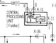
Guess that's how they did it back then? Most every car I've worked on (mostly newer) has had a separate in the fuse panel (probably the issue here lol) for the flasher unit.
But my main question...
Does anyone know how the wiring on the wiper motors works? The wiring diagram shows a similar setup as the flashers:
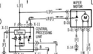
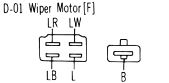
The blower motor has 5 wires in the connector. One is power, and the other 4 are different grounds to vary the speed of the motor. I'm guessing the wiper motors don't work the same. There are multiple wires in the connector(s), pictured here:
On the blower motor, I didn't really worry much about sticking 12v on it. Worst case, I spun the motor backwards (which did happen). On the wiper motor... a little more concerned, enough to not stick 12v on it.
Thinking out loud here, I would imagine that one of those terminals is either a ground or a positive and the other 4 are the opposite, with two being forwards high/low speed and two being backwards low/high speed.
Anyone got any advice here? Next thing to try might be tracing wires from the stalk switch. I would greatly appreciate it if someone could stick a multimeter on the wiper motor connector under the cowl and tell me what's getting power and when. I might try to work something with a wiper motor relay from the parts store. The trick, I think, will be getting that 1 second on/1 second off to be the right duration so I only get 90 degrees of wiper travel.
Turn signals get a little more complicated. The wiring diagram on Sgt Fox's FSM page (Foxed.ca - Mazda RX-7 Manuals shows the flasher relay in the CPU.
Guess that's how they did it back then? Most every car I've worked on (mostly newer) has had a separate in the fuse panel (probably the issue here lol) for the flasher unit.
But my main question...
Does anyone know how the wiring on the wiper motors works? The wiring diagram shows a similar setup as the flashers:
The blower motor has 5 wires in the connector. One is power, and the other 4 are different grounds to vary the speed of the motor. I'm guessing the wiper motors don't work the same. There are multiple wires in the connector(s), pictured here:
On the blower motor, I didn't really worry much about sticking 12v on it. Worst case, I spun the motor backwards (which did happen). On the wiper motor... a little more concerned, enough to not stick 12v on it.
Thinking out loud here, I would imagine that one of those terminals is either a ground or a positive and the other 4 are the opposite, with two being forwards high/low speed and two being backwards low/high speed.
Anyone got any advice here? Next thing to try might be tracing wires from the stalk switch. I would greatly appreciate it if someone could stick a multimeter on the wiper motor connector under the cowl and tell me what's getting power and when. I might try to work something with a wiper motor relay from the parts store. The trick, I think, will be getting that 1 second on/1 second off to be the right duration so I only get 90 degrees of wiper travel.
Last edited by rauq; Feb 16, 2013 at 09:35 PM.
Thread Starter
is a scrub
Joined: Jan 2013
Posts: 66
Likes: 0
From: Upstate SC
Edit: possibly... scratch all that. Looking at a diagram of how the wiper motor works (but not looking at the car itself, so I might be completely off), the motor itself never reverses, maybe like this?
http://static.howstuffworks.com/flas...-animation.swf
Never thought about it like that. Still doesn't explain what all the wires are for. Maybe low/high intermittent and low and high each have their own wire...?
Now I'm getting somewhere... you guys are awesome!
May just be an issue of getting a wiper relay with the right resistance (speed) so they stop at the bottom of travel and not halfway through. Or maybe I'll just do without intermittent and go with slow medium and fast. Man, I'm good.
Joined: Jun 2008
Posts: 8,376
Likes: 28
From: Chino Hills, CA
The motor never reverses; there's an interruptor switch assembly (like a big commutator ring) on the main drive gear in the motor unit, that 'tells' the motor where to stop in it's cycle with the wipers down. The wiper switch jumps that interruption to set the motor moving. The motor itself never reverses. The reversing action is done by a bellcrank and arm arrangement on the wiper arm linkage, just like in that animation.
Thread Starter
is a scrub
Joined: Jan 2013
Posts: 66
Likes: 0
From: Upstate SC
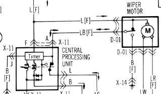
Well, the answer was right in front of me.
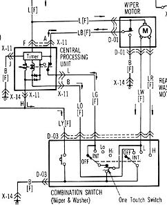
Intermittent low and high go through the CPU, regular low and high don't. Ground (X-14... a fairly universal ground) is black, low is blue/white, and high is blue/red. I put the black on ground and the blue/white on 12v and got low speed, and 12v on blue/red and got high speed.
With the low/high 12v's on an SPDT switch, I'll get 2 wiper speeds (no intermittent), and I'll have to cut power when the wipers are down to get them to stop there. Worth it, I think, for the simplicity of removing basically every harness in the car.
Only thing left to figure out is how the headlight motors work.
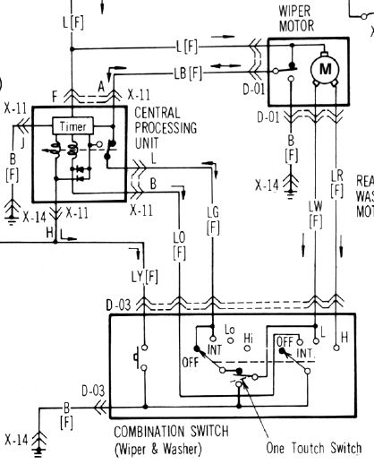
Joined: Jun 2008
Posts: 8,376
Likes: 28
From: Chino Hills, CA
They're somewhat similar; bellcranks with interruptor contacts on the drive gear. Motors never reverse; the interruptors index the up and down stop points. Separate feed for "Up" and "Down."
Thread Starter
is a scrub
Joined: Jan 2013
Posts: 66
Likes: 0
From: Upstate SC
So you're saying I can feed it 12v on the up side and it will stop at full up, and 12v on the down side and it will stay down? That sounds easy enough... obviously don't keep 12v on the up side when the headlight is already up, same for down.
Joined: Jun 2008
Posts: 8,376
Likes: 28
From: Chino Hills, CA
You'll want to look at the diagram, but essentially 'yeah'.
The "Lights Up" switch on the console can make the wiring diagram look more complicated at first (since you're looking at both that switch and the column 'lights' switch working in concert) but the relay and interruptor built into the headlight motor assembly takes care of most of the complexity.
The stock wiring actually keeps power on the 'down' side all the time, unless one switch or the other is set to "Up". That's why the console switch is wired to interrupt the column 'down' signal as well as sending "up". The interruptor stops power flow on the 'down' line when the lights are fully down, and stops power on the 'up' side when fully up.
If I remember correctly, if you activate both lines, all that happens is the lights keep cycling without stopping. Not recommended, though. Might cook one of the diodes if you left it that way too long.
& one lead is there to provide for the "lights" idiot light that illuminates only when the lights are not fully up or fully down.
Trending Topics
Thread Starter
is a scrub
Joined: Jan 2013
Posts: 66
Likes: 0
From: Upstate SC
I got it!
For future reference, if anyone needs a definitive answer... the white/red needs power for either the up or down motion, while the red (up) and red/yellow (down) only need power while being actuated. The headlight motor is already grounded so you don't have to worry about that.
For future reference, if anyone needs a definitive answer... the white/red needs power for either the up or down motion, while the red (up) and red/yellow (down) only need power while being actuated. The headlight motor is already grounded so you don't have to worry about that.