
Wiring harness help

Wiring harness help
hi guys,
since i still own the widebody (and haven't received solid offers), i'd like to go ahead and plan for the REW swap. here's where i need the forum's help as i am a total newb when it comes to wiring, which to me is harder than the physical install of the motor, so that's why i'd like to tackle this first and make sure i have it figured out.
i'll be installing the REW (with 12a front cover, GSL-SE oil pan, and FC CAS) using the PowerFC to control it and using the REW engine harness.
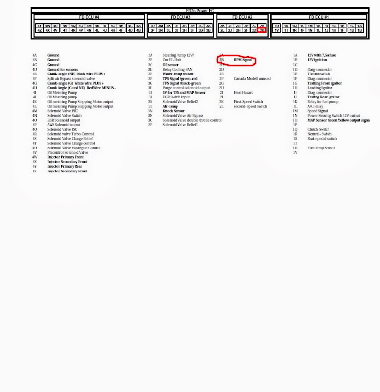
someone shared the following PowerFC pinout and i would like to create a similar one for the GSL-SE (i think this would make it easier but if not, please let me know).
here's my newb attempt at reading the GSL-SE wiring diagram and attempting to make sense of it:
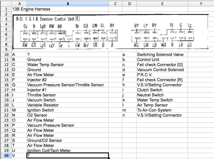
can someone confirm what i have is accurate and if not, help me fix it? thanks!
since i still own the widebody (and haven't received solid offers), i'd like to go ahead and plan for the REW swap. here's where i need the forum's help as i am a total newb when it comes to wiring, which to me is harder than the physical install of the motor, so that's why i'd like to tackle this first and make sure i have it figured out.
i'll be installing the REW (with 12a front cover, GSL-SE oil pan, and FC CAS) using the PowerFC to control it and using the REW engine harness.
someone shared the following PowerFC pinout and i would like to create a similar one for the GSL-SE (i think this would make it easier but if not, please let me know).
here's my newb attempt at reading the GSL-SE wiring diagram and attempting to make sense of it:
can someone confirm what i have is accurate and if not, help me fix it? thanks!
thanks 74rx4. i've updated my spreadsheet and will post the latest one (but will wait for other input(s) first though in case it needs correction).
in terms of sensors to use, would i want the GSL-SE water temp, and oil pressure (but it's not listed in the engine harness) sensors or stay with the REW's? i'm assuming the GSL-SE so dash would function correctly.
in terms of sensors to use, would i want the GSL-SE water temp, and oil pressure (but it's not listed in the engine harness) sensors or stay with the REW's? i'm assuming the GSL-SE so dash would function correctly.


Joined: Mar 2001
Posts: 31,833
Likes: 3,232
From: https://www2.mazda.com/en/100th/
thanks 74rx4. i've updated my spreadsheet and will post the latest one (but will wait for other input(s) first though in case it needs correction).
in terms of sensors to use, would i want the GSL-SE water temp, and oil pressure (but it's not listed in the engine harness) sensors or stay with the REW's? i'm assuming the GSL-SE so dash would function correctly.
in terms of sensors to use, would i want the GSL-SE water temp, and oil pressure (but it's not listed in the engine harness) sensors or stay with the REW's? i'm assuming the GSL-SE so dash would function correctly.
i think the FD oil pressure sender will work, actually its the same thread so you could probably use either one.
the water temp kind of sucks though, Mazda changed the thread in 1989, and the FD sensor reads a bit differently than the 74-88 sensor. i'm using an S5 sender on peepers, and it reads high, not sure if you can add a resistor or what
the water temp and oil pressure aren't on the engine harness, they are on the other side and just go straight to the gauges, which is nice.
i think the FD oil pressure sender will work, actually its the same thread so you could probably use either one.
the water temp kind of sucks though, Mazda changed the thread in 1989, and the FD sensor reads a bit differently than the 74-88 sensor. i'm using an S5 sender on peepers, and it reads high, not sure if you can add a resistor or what
i'll actually be using an fc waterpump (that's where the correct water temp sensor is, right?) and removing all other accessories...so basically waterpump and alternator only. not sure if it's an S4 or S5 housing though. will keep that in mind.
edit: water temp sensor for gauge is below the oil pressure sensor.
Last edited by craaaazzy; Aug 13, 2013 at 04:37 PM.
Trending Topics
DISCLOSURE: PLEASE DO NOT TAKE WHAT I WRITE HERE TO BE CORRECT AS I AM JUST LEARNING HOW TO READ WIRING DIAGRAMS...I COULD BE TOTALLY WRONG AND NOT KNOW IT.
alright guys, i've taken my REW harness and have labeled most connectors and have a slight better understanding than i did a few days ago. so the Emission harness (EM in the FSM, some call it the engine harness) contains only connectors 3 and 4 to the ECU. i would not have to modify anything on these 2 connectors (for now) but one would need to find connectors 1 and 2 since those connect mainly to the Front harness (F).
please help me make sure I'm understanding this correctly. connector 1 on the REW contains some vital items such as power to the ECU, ignitor, fuelpump relay, etc. looking at the wiring diagrams for both the REW and GSL-SE, is this how i would patch them together?
REW to GSL-SE
1A - not sure where to pull this from yet
1B - get from X-07 connector on GSL-SE F harness, wire BR
1K - wire fuel pump directly to battery with relay using this as its switch
1Q - get from B-02 connector on GSL-SE F harness, wire RY
1R - get from B-05 connector on GSL-SE F harness, wire LB
since the stock MAP sensor is on the REW F harness, then i would need to create my own. MAP has 3 wires G/Y goes to 1O, BR/W can be pulled from BR/W on the X-05 connector, and B/LG can be pulled from BR/B on the X-05 connector also. B/LG also goes to the diagnosis connector which i don't believe i'll need.
i'm not sure how the ignitor/coils will work yet (that's why i don't have anything for the Tach - 2B) as i haven't looked into it but if you are familiar, please provide any insight.
also trying to figure out the use of the FC CAS. here's an except from a PFC install guide for the FC:
"CAS:
Make sure you use shielded wires from the ECU to the CAS. This wires are very important for
ignition control of the ECU. Electrical devices like igniter, plug- wires and ignition coils may
influence the CAS signal which may lead to improper timing control and engine damage. For this
reason, please do not use regular wires for CAS use shielded wires instead. You can solder the
green and the red wire together, them are connected to 4H pin on Apexi PowerFC. Make sure, the
black and the white wire for NE+ and G+ are connected properly. Please pay special attention to the connectors which will join the CAS and the wiring. On the CAS side of connector the wires red and green are used for NE+ and GE+ on the wiring side to the ECU the colour will change to black (NE+) and white (G+)."
please let me know if i'm reading the above correctly...
W from B1-48 connector from REW EM harness goes to G from E-08 on the CAS
B from B1-49 connector from REW EM harness goes to R from E-08 on the CAS
this was never mentioned but...
R and G from B1-48/49 connectors from REW EM harness go to L and W from E-08 on the CAS? both are (-) but there was

RX-7 NUT
Joined: Aug 2007
Posts: 444
Likes: 1
From: California
Basically sincve you are going single turbo w/ a power FC you arew going to have to do the single turbo harness delete. Once you go that hook it up like you would be with any T2 motor (theres alot of writeups) i am going to go haltech with a flying lead for mine so i dont have to worry about all of this. Some of the info here helped me whne i was trying to figure some shtuff out as well.
https://www.rx7club.com/1st-generati...ite-up-764389/
https://www.rx7club.com/1st-generati...w-redo-715412/
I had a TON more links but i had to wipe my computer and have yet to refind them all.
https://www.rx7club.com/1st-generati...ite-up-764389/
https://www.rx7club.com/1st-generati...w-redo-715412/
I had a TON more links but i had to wipe my computer and have yet to refind them all.
Joined: Aug 2011
Posts: 3,078
Likes: 42
From: Cambridge, Minnesota
REW to GSL-SE
1A - not sure where to pull this from yet
1B - get from X-07 connector on GSL-SE F harness, wire BR
1K - wire fuel pump directly to battery with relay using this as its switch
1Q - get from B-02 connector on GSL-SE F harness, wire RY
1R - get from B-05 connector on GSL-SE F harness, wire LB
since the stock MAP sensor is on the REW F harness, then i would need to create my own. MAP has 3 wires G/Y goes to 1O, BR/W can be pulled from BR/W on the X-05 connector, and B/LG can be pulled from BR/B on the X-05 connector also. B/LG also goes to the diagnosis connector which i don't believe i'll need.
i'm not sure how the ignitor/coils will work yet (that's why i don't have anything for the Tach - 2B) as i haven't looked into it but if you are familiar, please provide any insight.
1B - Check to see if this is Ignition 1 or Ignition 2 power if you can. The difference is one's on while the key is in the ACC position (radio powered on) and RUN (power windows, relays click on, basically the entire car is on for when it's running) so be sure to run it to the right wire.
1K - Make sure this is the wire that triggers the relay to turn on. If it is you're completely correct.
1Q - If you would like you can probably ground this wire. The clutch switch is grounded when the clutch pedal is depressed and to avoid having to press the clutch on startup you can ground the wire. Would help with remote starters and the like. Not necessary, just can be a nice thing if you would like to avoid pressing the pedal - who knows.
1R - This is necessary for emissions, not much else - and you're correct.
MAP - You'd be getting a MAP sensor from an FD and wiring it into the harness via your custom proposal correct? If so be careful and I'd probably just wire in the whole thing separate to make sure everything goes where it should. I did this by extending my wiring and placing the Knock Control Unit and Pressure Sensor down by the TII ECU just so I knew where they were and that they're protected.
Coils - I can't speak for FD coils, but TII ones run off of Main Relay power by one plug and have timing set by the ECU which comes to the coil via a different plug. On the trailing coil there's a wire that is used for the tach. I just spliced mine into the stock harness from the TII coil pack.
Sounds like you're on the right track, keep me updated!
Austin

Thread
Thread Starter
Forum
Replies
Last Post