
Twin Turbo FB?

Joined: Jul 2007
Posts: 1,663
Likes: 0
From: Charleston, South Carolina
 haha
haha


i have a question for arghx. im thinking about running the FD twins in a parallel setup. looking over the diagrams it appears as though the pre-control valve on the secondary turbo functions the same way as a wastegate. could i join the wastegate actuator arm onto the precontrol actuator arm, and use them together as twin wastegates.
its either that or welding them up entirely and getting an external wastegate i guess.
thanks.
its either that or welding them up entirely and getting an external wastegate i guess.
thanks.
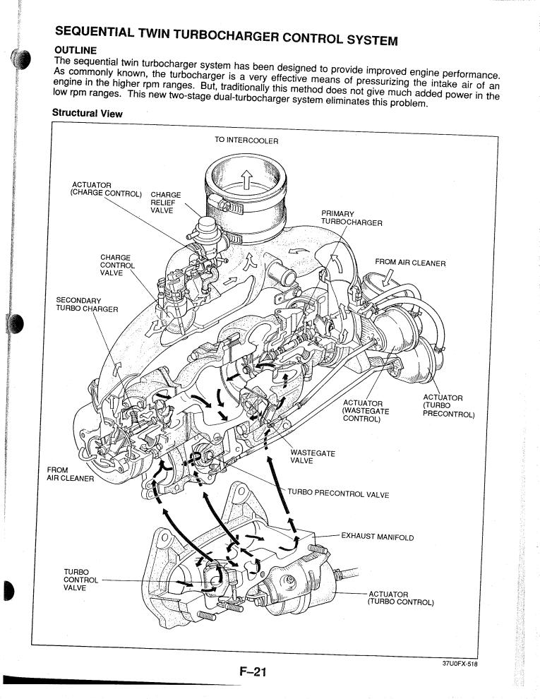
To explain further: the precontrol actuator itself works in the same way as a wastegate actuator, but it is not actually bleeding exhaust away from the turbine wheels completely. It opens a passageway to divert exhaust gases from the primary turbo to the secondary turbo. The wastegate diverts exhaust gases from both turbos. It is only active after the secondary turbo comes online, about 4000rpm. Normally when you do full non sequential you open the precontrol permanently. The precontrol valve is in the turbo assembly, and as I've mentioned it's pressure controlled like a wastegate. The more pressure acting on the actuator, the more the precontrol valve opens (once spring force has been overcome). As the precontrol valve opens, exhaust begins to feed the secondary turbo (which is at this point dumping boost back into the air cleaner). In this way boost pressure is controlled before the secondary turbo comes online.
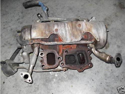
That's the backside of the FD HT12 twin turbo assembly, the flanged side that bolts to the exhaust manifold. The left passageway always feeds the primary turbo. The middle passageway goes to the precontrol valve in the turbo assembly itself. You can see the bottom actuator looking thing connected to it, that's the precontrol. The passageway on the far right is for the turbo control. The turbo control valve is in the exhaust manifold and should not be confused with the precontrol. It's not duty controlled like the wastegate and precontrol--it's an on/off deal. The actuator uses vacuum on one side and pressure on the other (one solenoid for each).
So exhaust flows, in a way, from left to right--> first to the leftmost passageway, then through the middle passageway (precontrol during the prespool period), and finally through the rightmost passageway once the turbo control valve opens. When you go non sequential the middle and right passages will always be open. Here's the FD exhaust manifold:
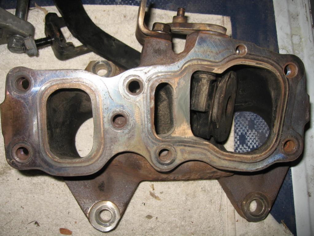
The way the manifold is oriented in the pic, the exhaust always flows through the leftmost passage. The middle is for precontrol and the right passage is for turbo control (you can see the flapper door here).
When doing a full non sequential conversion you can also modify the exhaust manifold for better flow in addition to porting the wastegate :
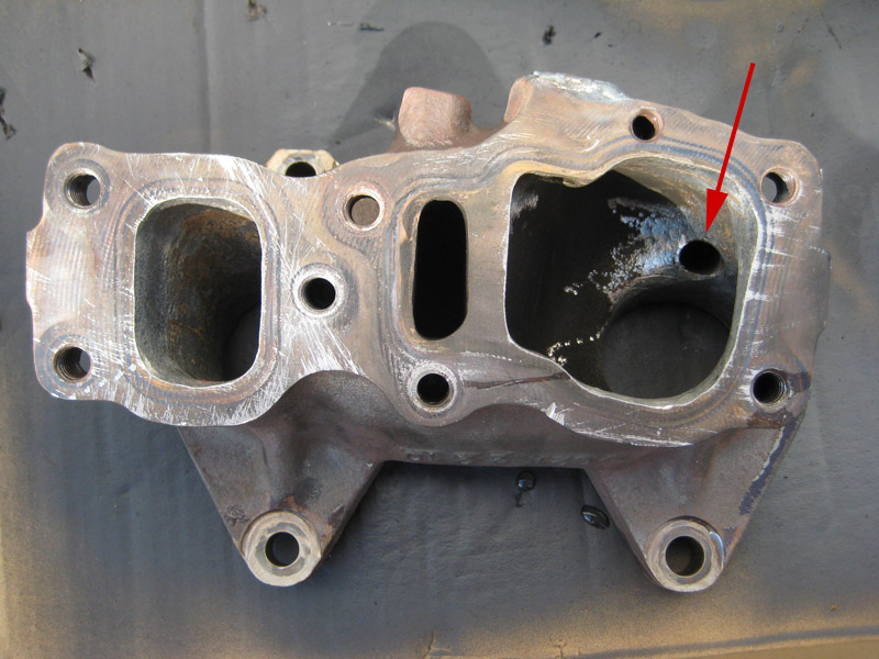
disregard the arrow
Another description of how it all works:
How Non Sequential Turbos Work
Just review to how non sequential turbos work: the precontrol (inside the turbo assembly) is usually welded open. The turbo control valve (in the exhaust manifold) is removed completely. The charge control valve (in the Y pipe which connects the two turbos) is removed and so is the charge relief valve, which looks like an OEM blowoff valve. The holes in the Y pipe are plugged up. The wastegate passage is ported and sometimes the flapper is replaced. I don't think boost control is a huge issue on a 12A though. A mild wastegate port should be fine IMO. Boost is controlled with the wastegate actuator only.
I question how well the FD twins will spool in non sequential form on a 12A though. They're already not very responsive on an FD 13B-REW. For nonsequential use I recommend trying to acquire the twins off a 13B-RE Cosmo engine. They are smaller than the twins for the FD, and NOBODY wants them. They are worth nothing really, and you may be able to find some in good shape for cheap. Post a WTB ad in the 2nd gen section.
The Cosmo twins are twin HT10 turbos. The FD is twin HT12 turbos (slightly different in 99 spec form). The Cosmo 20B has one HT15 turbo and one HT10. The 12a Turbo has a single scroll HT18 turbo. The 13B Turbo II engines have the HT18S-2S turbos which have divided turbine housings (a little different between s4 and s5).

Senior Member
Joined: Nov 2009
Posts: 346
Likes: 3
From: Australia
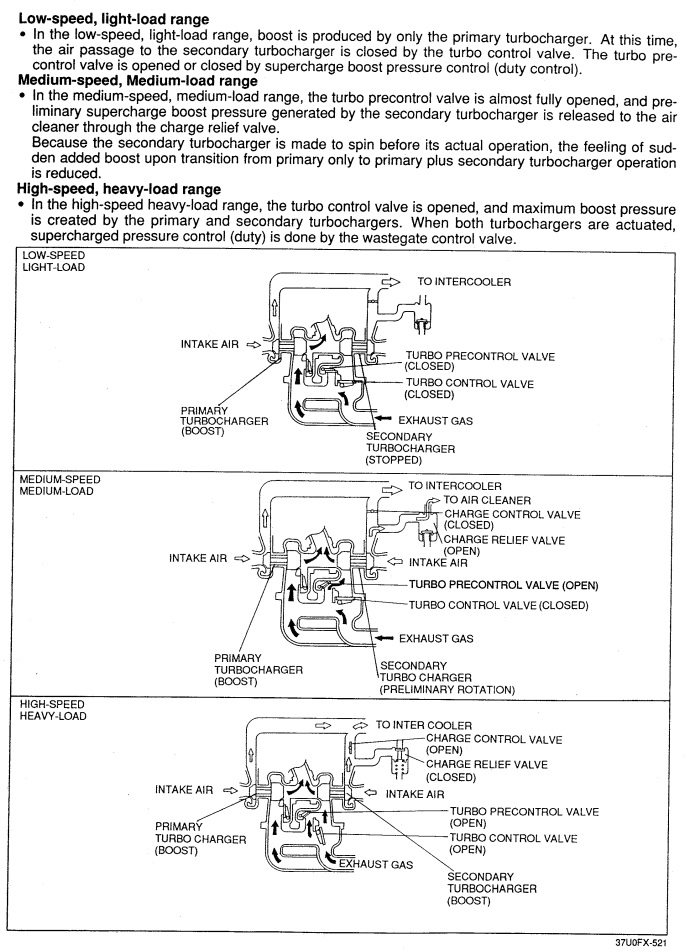
Hmmm. Well I would have made a custom exhaust manifold with fully separate runners into each side of the turbo assembly. Judging from the diagram below it appears as though the pre-control valve vents into the post-turbine area of the assembly, which is why I thought it would function as a wastegate on the secondary turbo. However if the exhaust gas goes through the primary turbo pre-turbine I can see why it wouldn't work.
I'm also beginning to be concerned that it would be extremely difficult to prevent the dump pipe fouling on the steering box (right hand drive here in australia), so I might need to source different twins. I will look into the cosmo HT-10 twins as I like smaller turbos, this is for a low boost street car.
Thanks for all the info!

Joined: Mar 2001
Posts: 31,857
Likes: 3,243
From: https://www2.mazda.com/en/100th/
I'm also beginning to be concerned that it would be extremely difficult to prevent the dump pipe fouling on the steering box (right hand drive here in australia), so I might need to source different twins. I will look into the cosmo HT-10 twins as I like smaller turbos, this is for a low boost street car.
Thanks for all the info!
Thanks for all the info!
Senior Member
Joined: Nov 2009
Posts: 346
Likes: 3
From: Australia
do you guys have any pics of these cosmo HT-10s? I'd like to see if they won't foul the steering box. i guess the most important this is how the dump pipe is orientated.
may have to go back to the original idea of nissan t2's and make up a custom dump pointing straight down. glad i haven't spent any money yet..
may have to go back to the original idea of nissan t2's and make up a custom dump pointing straight down. glad i haven't spent any money yet..
Joined: Mar 2001
Posts: 31,857
Likes: 3,243
From: https://www2.mazda.com/en/100th/
it turns out we have both sets of cosmo twins at the shop! and the 20B flanges we made don't fit the cosmo, they are both 3 bolt, but the 13b is smaller.
Joined: Mar 2001
Posts: 31,857
Likes: 3,243
From: https://www2.mazda.com/en/100th/
do you guys have any pics of these cosmo HT-10s? I'd like to see if they won't foul the steering box. i guess the most important this is how the dump pipe is orientated.
may have to go back to the original idea of nissan t2's and make up a custom dump pointing straight down. glad i haven't spent any money yet..
may have to go back to the original idea of nissan t2's and make up a custom dump pointing straight down. glad i haven't spent any money yet..
Senior Member
Joined: Nov 2009
Posts: 346
Likes: 3
From: Australia
Finally found a set of twins, they are set up as parallel, which is going to be easier to install on my s1 I think. But I highly doubt the dump pipe will clear the steering box without some mods. (RH drive in Australia)
So that got me thinking. Perhaps I could replace the turbine housings and make a custom dump pipe which points straight down and then 90deg underneath the rear turbo. Do you guys know of any housings that will fit? Preferably not new so they're cheap, and around the 0.5 A/R range.
So that got me thinking. Perhaps I could replace the turbine housings and make a custom dump pipe which points straight down and then 90deg underneath the rear turbo. Do you guys know of any housings that will fit? Preferably not new so they're cheap, and around the 0.5 A/R range.


Thread Starter
Senior Member
Joined: Sep 2008
Posts: 543
Likes: 0
From: Glen Burnie, Maryland
Its going slow lol. Got the intercooler and rrfpr. Need pump and intercooler piping now. Carb needs to be prepped and gotta figure out the oil lines setup. But need to get a new trans mines makin funny noises. Found someone with one for 75 bucks. He said its freshly rebuilt recent
Joined: Mar 2001
Posts: 31,857
Likes: 3,243
From: https://www2.mazda.com/en/100th/
Finally found a set of twins, they are set up as parallel, which is going to be easier to install on my s1 I think. But I highly doubt the dump pipe will clear the steering box without some mods. (RH drive in Australia)
So that got me thinking. Perhaps I could replace the turbine housings and make a custom dump pipe which points straight down and then 90deg underneath the rear turbo. Do you guys know of any housings that will fit? Preferably not new so they're cheap, and around the 0.5 A/R range.
So that got me thinking. Perhaps I could replace the turbine housings and make a custom dump pipe which points straight down and then 90deg underneath the rear turbo. Do you guys know of any housings that will fit? Preferably not new so they're cheap, and around the 0.5 A/R range.
the FD turbos are roughly two t25's on a cast manifold, there are no other turbine housings for it, that keep the twin turbo config
Senior Member
Joined: Nov 2009
Posts: 346
Likes: 3
From: Australia
Received the twins today. The turbo control valve is welded open, but the precontrol valve is still functional, and the plate behind it removed.. I guess the previous owner was using it as a wastegate on the rear turbo...?
As for my plans, I will have to make a custom manifold with external wastegate. This seems like the easiest option since only one of the housings has an internal gate which can be welded shut. And possibly also make a new centre section with the dump pipe flange. In stock form it sits right next to the steering box and points straight at it. So unless the manifold moves it significantly rearward I will have to do something about it as well. For now I will be happy to just get the damn bolts off! lol
As for my plans, I will have to make a custom manifold with external wastegate. This seems like the easiest option since only one of the housings has an internal gate which can be welded shut. And possibly also make a new centre section with the dump pipe flange. In stock form it sits right next to the steering box and points straight at it. So unless the manifold moves it significantly rearward I will have to do something about it as well. For now I will be happy to just get the damn bolts off! lol
Senior Member
Joined: Nov 2009
Posts: 346
Likes: 3
From: Australia
I guess there is no way of talking you out of the carb, so I'm not going to bother. I wouldn't trust a carb for higher boost and pump gas because there is no electronic spark advance to adjust timing. You may want to skip running boost controllers altogether then. The simplest thing is to run at the 7-8psi of the factory wastegate/precontrol by connecting the pressure sources off the compressor outlet directly to the actuators with no boost controller or restricter. There is a chance you will have to port the wastegate to hold this boost.
You may be able to get away with just one rpm activated switch and some relays to control everything. Here's an el cheapo: http://www.racerpartswholesale.com/p...ue_Shift_Light or you can go MSD. I've used the MSD ones but I'm not sure if they are really any better than the cheap one.
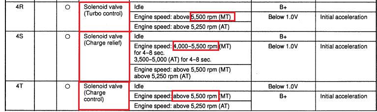
That's the factory FD control logic for very low throttle. At high throttle the transition point is 4000rpm. So at 4000rpm (you could still adjust the rpm it later) you will need to switch your charge control, charge relief, the two turbo control solenoids, and you will want to begin opening the wastegate. Technically the charge relief solenoid isn't supposed to come online until at least 2000 rpm (which would require a window switch), but I don't think it matters that much. So here is one idea:
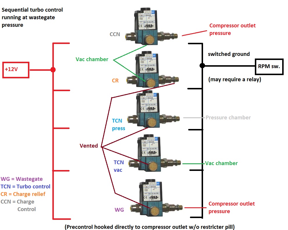
Under 4000rpm:
-- Charge control actuator receives vacuum from vac chamber
-- Charge relief receives vacuum from vac chamber (valve opened)
-- Turbo control actuator (pressure side) is vented
-- Turbo control actuator (vacuum side) is vented
-- Wastegate is vented (held shut to improve spool), 2nd port on actuator capped
-- Pre control valve is connected directly to the compressor outlet to control boost via spring pressure, 2nd port on actuator capped
Over 4000rpm:
-- Charge control actuator receives pressure from compressor outlet
-- Charge relief valve vented (valve closed)
-- Turbo control actuator (pressure side) receives pressure from chamber
-- Turbo control actuator (vacuum side) receives vacuum from chamber
-- Wastegate receives compressor outlet pressure in order to control boost. An MBC or EBC could be installed in-line, but higher boost levels could be dangerous
-- Pre control continues to receive compressor outlet pressure and is thus held in the full open position.
I have no idea how the boost pattern would be on a carb'd 12A turbo. No clue. And I've never actually tried that exact plumbing personally, but on paper it should work.
You may be able to get away with just one rpm activated switch and some relays to control everything. Here's an el cheapo: http://www.racerpartswholesale.com/p...ue_Shift_Light or you can go MSD. I've used the MSD ones but I'm not sure if they are really any better than the cheap one.
That's the factory FD control logic for very low throttle. At high throttle the transition point is 4000rpm. So at 4000rpm (you could still adjust the rpm it later) you will need to switch your charge control, charge relief, the two turbo control solenoids, and you will want to begin opening the wastegate. Technically the charge relief solenoid isn't supposed to come online until at least 2000 rpm (which would require a window switch), but I don't think it matters that much. So here is one idea:
Under 4000rpm:
-- Charge control actuator receives vacuum from vac chamber
-- Charge relief receives vacuum from vac chamber (valve opened)
-- Turbo control actuator (pressure side) is vented
-- Turbo control actuator (vacuum side) is vented
-- Wastegate is vented (held shut to improve spool), 2nd port on actuator capped
-- Pre control valve is connected directly to the compressor outlet to control boost via spring pressure, 2nd port on actuator capped
Over 4000rpm:
-- Charge control actuator receives pressure from compressor outlet
-- Charge relief valve vented (valve closed)
-- Turbo control actuator (pressure side) receives pressure from chamber
-- Turbo control actuator (vacuum side) receives vacuum from chamber
-- Wastegate receives compressor outlet pressure in order to control boost. An MBC or EBC could be installed in-line, but higher boost levels could be dangerous
-- Pre control continues to receive compressor outlet pressure and is thus held in the full open position.
I have no idea how the boost pattern would be on a carb'd 12A turbo. No clue. And I've never actually tried that exact plumbing personally, but on paper it should work.
With enough time and trouble you could make it work, but would it be worth it? 4000 rpm really is fine, trust me I have played around with transition points plenty. If you're going to be stone age (carb), keep it stone age the whole way through. Otherwise get a standalone and control the twins with that. You want an airflow meter to set up turbo transition, something more complicated than even Mazda designed, but you want a locked distrbutor and a bunch of jets controlling timing and fuel?
Thread Starter
Senior Member
Joined: Sep 2008
Posts: 543
Likes: 0
From: Glen Burnie, Maryland
ARGHX, just wantin to let you know its gettin closer and closer. Got only a couple more thinks to pick up for the car. But my main think is what to do about the plumbing. Im gonna get rid of the beehive. Gonna see if i can source a FC oil cooler. But i was wondering how to run the pressur line from and what to do about the drain lines. I was thinking of tappin the orfice on the turbos to accept a AN fitting and go to a Y and single to the oil pan. But not sure. Just wondering what you would think. Thanks
Joined: Mar 2001
Posts: 31,857
Likes: 3,243
From: https://www2.mazda.com/en/100th/
ARGHX, just wantin to let you know its gettin closer and closer. Got only a couple more thinks to pick up for the car. But my main think is what to do about the plumbing. Im gonna get rid of the beehive. Gonna see if i can source a FC oil cooler. But i was wondering how to run the pressur line from and what to do about the drain lines. I was thinking of tappin the orfice on the turbos to accept a AN fitting and go to a Y and single to the oil pan. But not sure. Just wondering what you would think. Thanks
the feed should be simple, one of those racing beat oil pressure/temp blocks would give you a spot for filtered oil.
you WILL need an FC oil cooler, the FD turbos add much heat into the oil
Thread Starter
Senior Member
Joined: Sep 2008
Posts: 543
Likes: 0
From: Glen Burnie, Maryland
on the stock FD the front turbo drains into the front cover (on 83+ front covers there is an undrilled boss for the turbo drain) and the rear turbo drains into the bottom of the rear iron. not sure how you'd do that....
the feed should be simple, one of those racing beat oil pressure/temp blocks would give you a spot for filtered oil.
you WILL need an FC oil cooler, the FD turbos add much heat into the oil
the feed should be simple, one of those racing beat oil pressure/temp blocks would give you a spot for filtered oil.
you WILL need an FC oil cooler, the FD turbos add much heat into the oil
Joined: Mar 2001
Posts: 31,857
Likes: 3,243
From: https://www2.mazda.com/en/100th/
Thread Starter
Senior Member
Joined: Sep 2008
Posts: 543
Likes: 0
From: Glen Burnie, Maryland
K. I did see a thread about tapping the front cover for a drain. When i get to that point ill look into what i can do. And I may get a rotor kit and a seal kit. Then swap the oil pump with a GSL-SE pump and put the three window bearings in. Also foun a local Rotary shop that can do a street port for 200. May have that done also. So many things to do right now lol.