
TurboII swap Project: Complete vehicle reqwiring part 1: chassis

Thread Starter
Joined: Jan 2002
Posts: 2,397
Likes: 1
From: Mound, MN
TurboII swap Project: Complete vehicle reqwiring part 1: chassis
Spring has FINALLY arrived here in MN, and I, at last, got out into the garage to work on the 7. I started the installation of the American Autowire Power20 wiring harness. Now, I should mention that I am a seasoned GM service technician and specialize in electrical and CAN/MOD diag and repair (wiring and computers). And since this kit is GM based, and GM has kept the same wire colors (more or less) for 50 years, I figured I could handle it. This is not the project for the faint of heart.
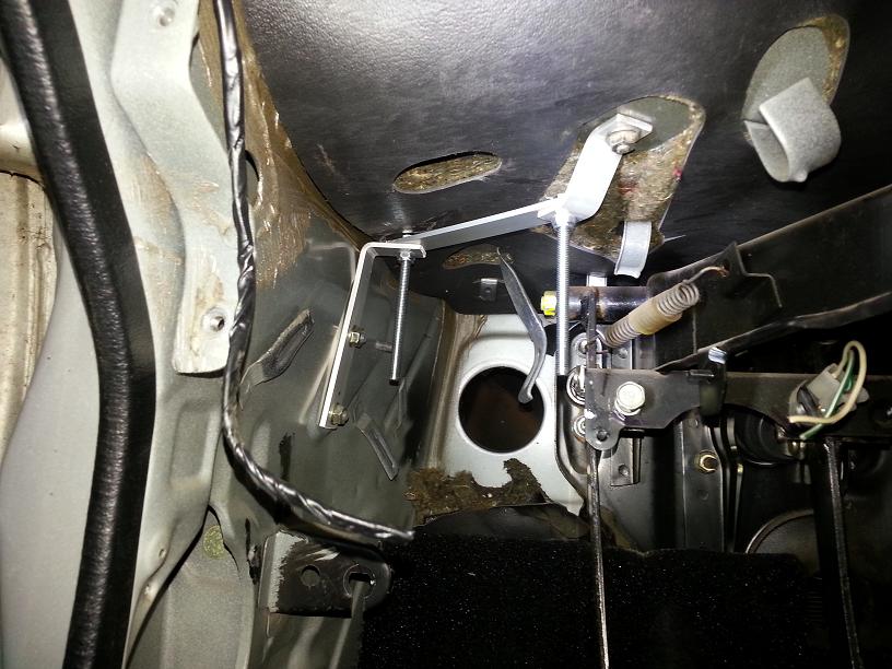
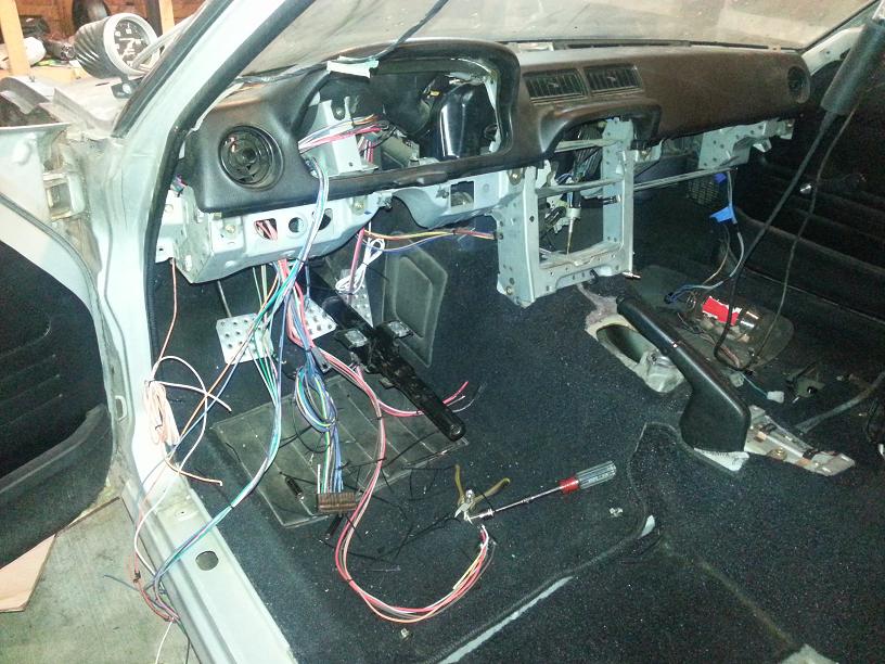
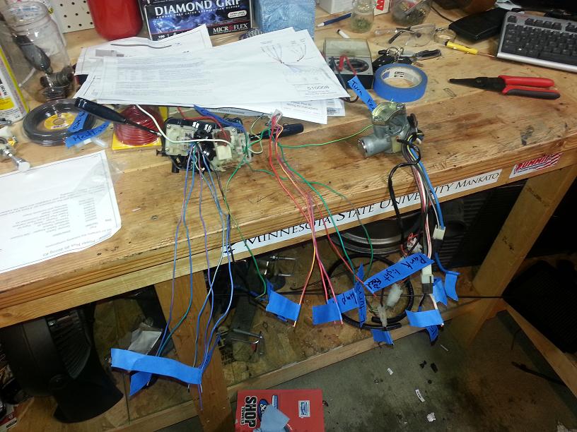
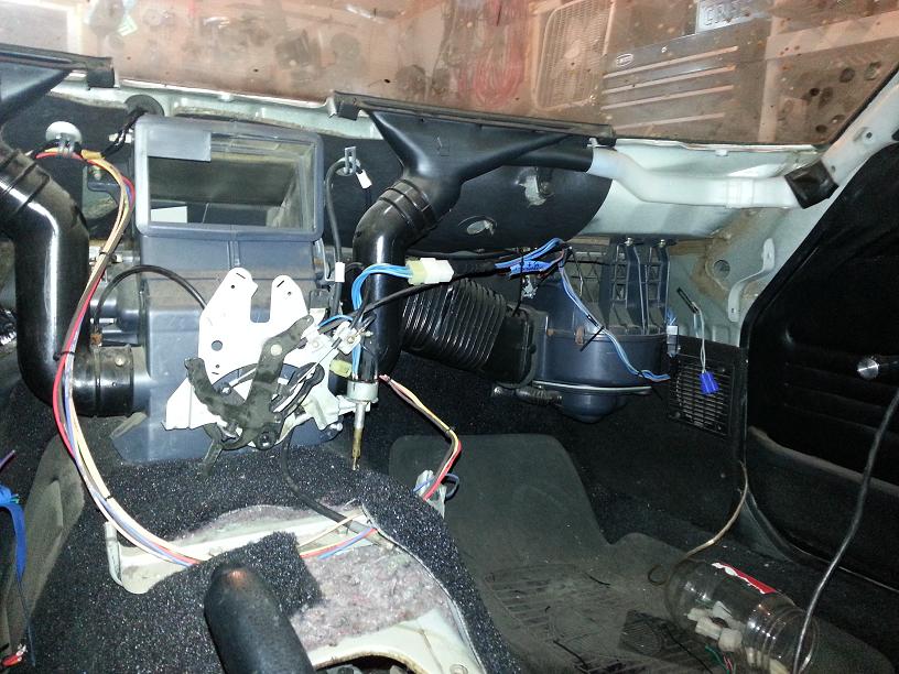
I mounted the fuse block in the same general area as stock, but I mounted it to the chassis and not the dash. I have removed all wiring from the dashboard to ease in final assembly. During teardown, there was a huge wiring harness attached to the dash, but the only part of it I am reusing is the blower control harness, which I isolated. Minus the steering column and HVAC controls, the dash comes off in minutes now.
In this first pics, you can see the bracket I fabbed up to mount the fuse block and the first basic check for fit. I ended up mounting the block 180 around from how I first mocked it here in the second pic, Ill go into that later.
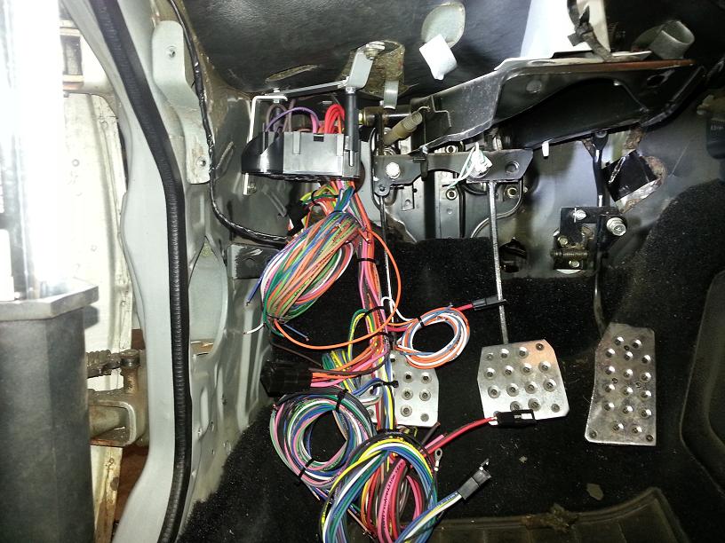
I mounted the block, and reinstalled the dashboard assm to check for clearances, making sure to install all the HVAC plumbing; there is not a whole lot of room under here. Also started basic seperation of the harness and routing. Nothing to spectacular looking here, but it a lot of work. If I can give you one big piece of advise; ZIP TIES ARE YOUR FRIEND! I found myself constantly cutting off and then adding zip ties to keep everything organized. This kit is designed for a fullsize GM and is MUCH longer than needed.
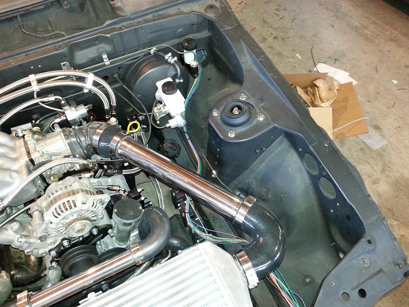
I also pulled the Engine/Front section of the harness through to the engine bay, but I have no plans to set that up till I get the rest of the harness routed and connected in the dashboard. I also want to get the Haltech Sprint RE Set in the car first as well, so Ill just keep truck'n on the dash.
I mounted the fuse block in the same general area as stock, but I mounted it to the chassis and not the dash. I have removed all wiring from the dashboard to ease in final assembly. During teardown, there was a huge wiring harness attached to the dash, but the only part of it I am reusing is the blower control harness, which I isolated. Minus the steering column and HVAC controls, the dash comes off in minutes now.
In this first pics, you can see the bracket I fabbed up to mount the fuse block and the first basic check for fit. I ended up mounting the block 180 around from how I first mocked it here in the second pic, Ill go into that later.
I mounted the block, and reinstalled the dashboard assm to check for clearances, making sure to install all the HVAC plumbing; there is not a whole lot of room under here. Also started basic seperation of the harness and routing. Nothing to spectacular looking here, but it a lot of work. If I can give you one big piece of advise; ZIP TIES ARE YOUR FRIEND! I found myself constantly cutting off and then adding zip ties to keep everything organized. This kit is designed for a fullsize GM and is MUCH longer than needed.
I also pulled the Engine/Front section of the harness through to the engine bay, but I have no plans to set that up till I get the rest of the harness routed and connected in the dashboard. I also want to get the Haltech Sprint RE Set in the car first as well, so Ill just keep truck'n on the dash.
Thread Starter
Joined: Jan 2002
Posts: 2,397
Likes: 1
From: Mound, MN
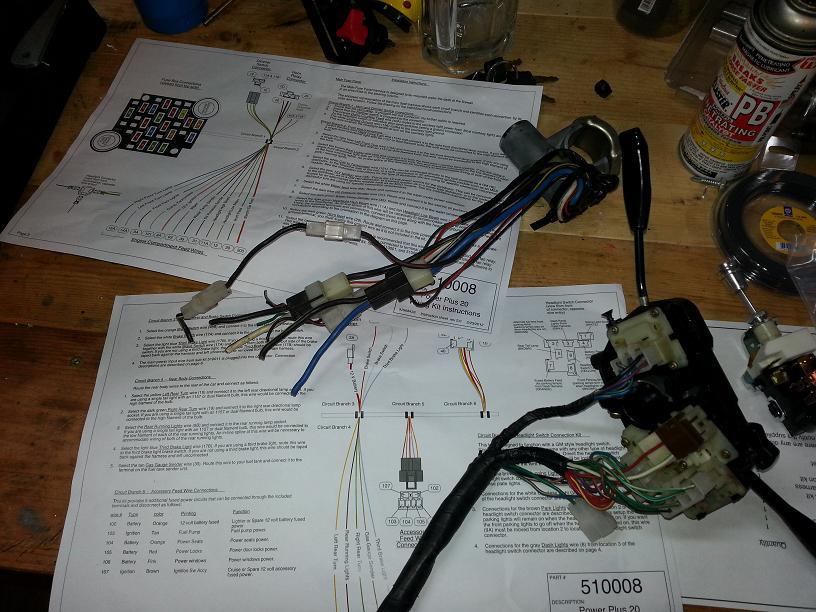
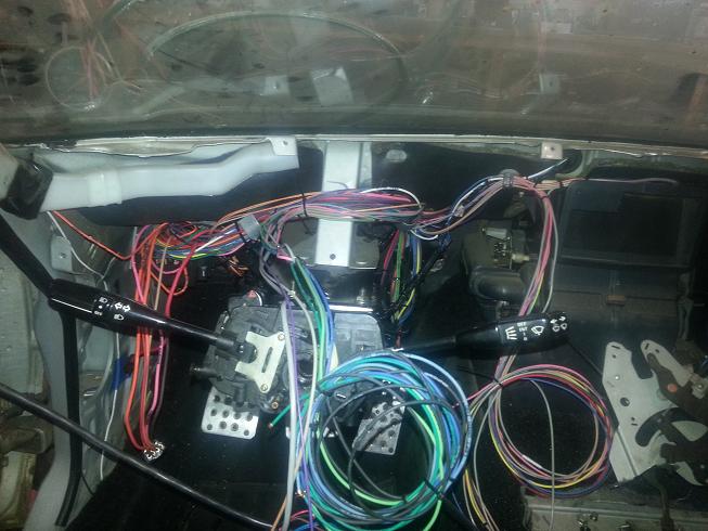
After some work I got the harness more or less where I want it, but still very rough. It looks like a real mess, but I have shortened anything yet, so there is still a lot of bulk wire laying around. I pulled about 4 circuits that I knew I had no use of. Off the top of my head they were the tach signal feed, the dimmer switch feed, a courtesy light wire to the light switch ect. The kit is designed for a dash mounted headlight switch, and a floor mounted high-beam switch. This was confusing at first but I soon figured out how to integrate it with the factory multi-function switch. The kit is wired for a GM turn signal switch (which are complicated) but that too proved to work with the factory switch after a little reorganization of wires.
Once I got the wires basically where I wanted them, I began stripping the factory column controls and the ignition switch. I also labeled everything so I wouldn't be constantly checking the wiring diagram. Now I had a thread couple months back asking if anyone knew the amp rating of the ign switch. Now I don't know it now, but based on wire size of the switch to its connections on the kit, there should be NO problem. The wires on this thing are HUGE. That being said, the wire colors are VERY confusing, For example, there is a black and white wire off the switch that changes to a black and yellow (after connector) and a black and yellow that changes to a black and white. IF your looking at the Factory wiring diagrams for the ign, all colors are AFTER CONNECTOR. And it has two IGN feeds, but Im only using one.
Next step is to tightly loom the harness and secure it to the chassis, and then connect all the turn signal, headlights, ignition and wiper controls.
Note to anyone taking this on, separate and save the entire wiper harness. I did not and will likely not have any Intermittent wiper speed. High and low speed are a simple hookup, but if I had the forethought to de-loom and save that harness, the wipers would have been a 1 wire hookup.
but oh well. More updates coming on this thread as I complete the chassis wiring, when I wire the Haltech, I will likely start a new one. There are A LOT of specific details on the install of this harness that I did not go into, any questions on something specific, just ask. Peace.
Thread Starter
Joined: Jan 2002
Posts: 2,397
Likes: 1
From: Mound, MN
Got a little more accomplished this afternoon. Finished basic looming and routing of the dash sections. Also got the blower circuits run and cut down, just need to tie it in to the kit. Everything is set to connect and solder, probably got 50 connections to make. I am considering trying to re-terminal some of the connectors for a cleaner look, but this would make for more difficult diagnosis if there was a problem down the road, or if I ever sell the car.
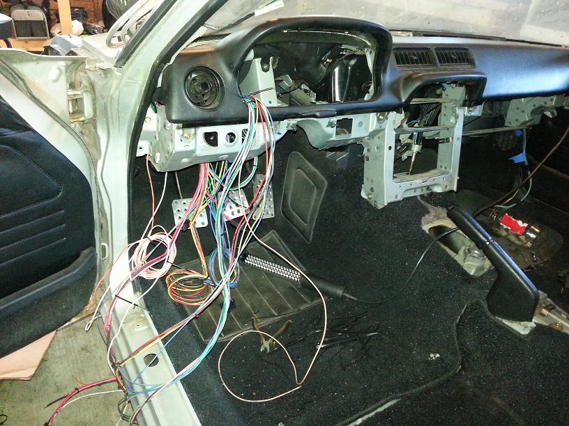
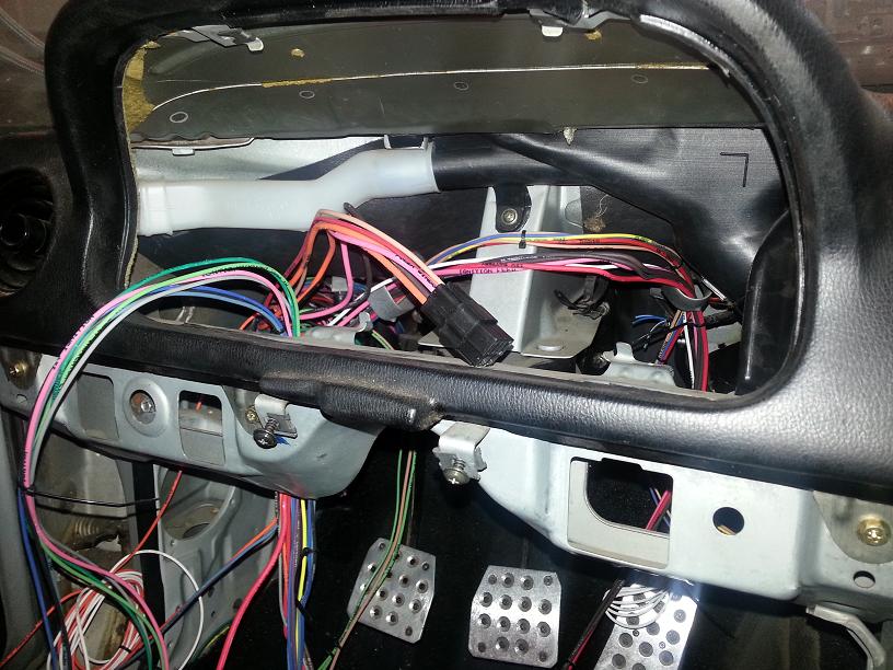
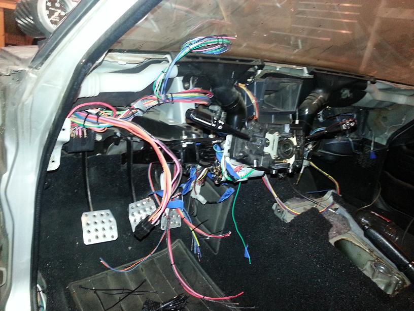
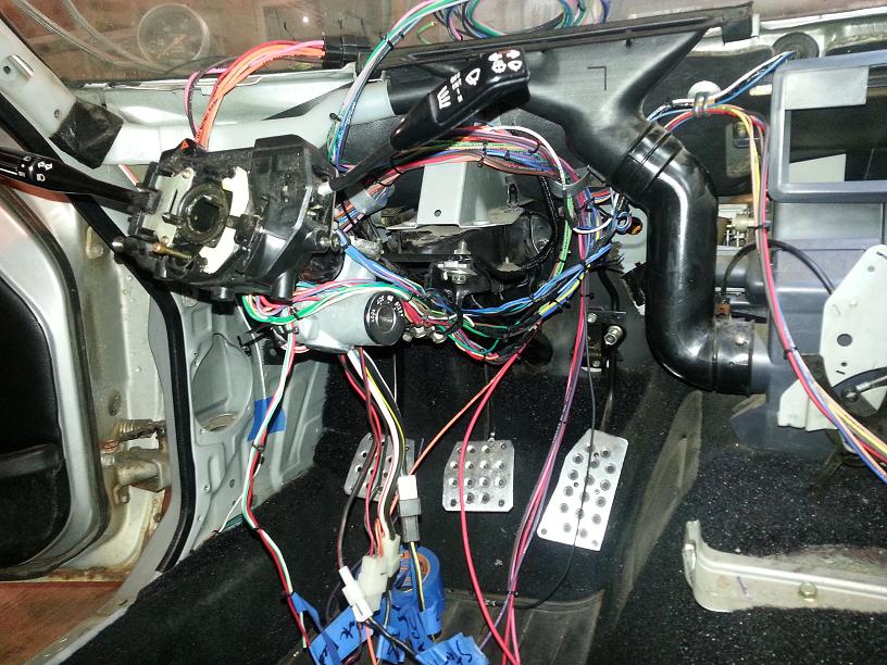
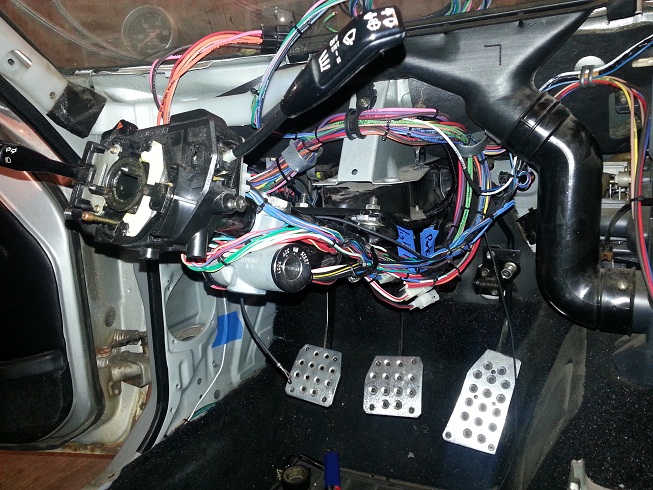
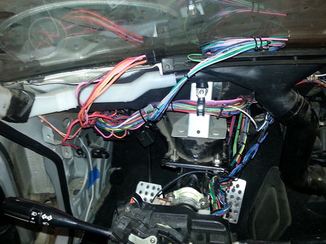
Anyways, here's some shots of the looming with the dash and controls on. I also mounted the front bumper, but that's another project. Key here is to consistently check and recheck clearances, as you don't want to be redoing something after its been sectioned and soldered. I have run into the small problem that I need to fuse the headlight circuit (due to GM design) but that's not the end of the world.

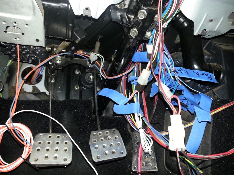
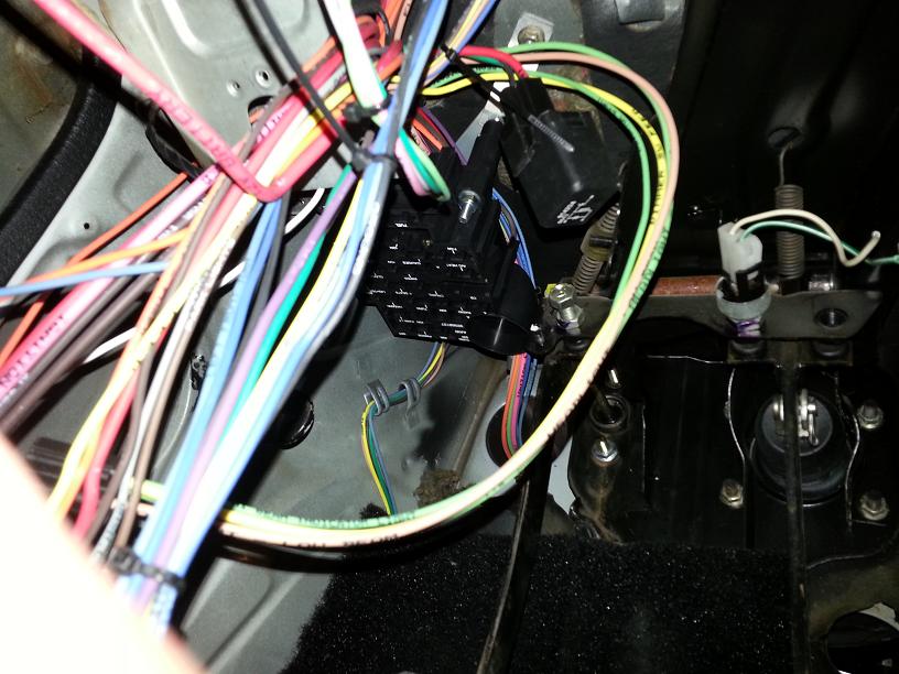
Once I had things tight and where I wanted them going, I pulled the dash and remounted the column. The plan is to individually zip tie wires together for each connection, going switch by switch, and double check all connections. FYI, the group of heavy wires on a black connector is the Aux power connector. Its designed for power windows and seats, but ill be using it for Laptop power, washer power and other console needs. The last pic is the heater circuit, cut down and run on the recirculate cable.
Anyways, here's some shots of the looming with the dash and controls on. I also mounted the front bumper, but that's another project. Key here is to consistently check and recheck clearances, as you don't want to be redoing something after its been sectioned and soldered. I have run into the small problem that I need to fuse the headlight circuit (due to GM design) but that's not the end of the world.
Once I had things tight and where I wanted them going, I pulled the dash and remounted the column. The plan is to individually zip tie wires together for each connection, going switch by switch, and double check all connections. FYI, the group of heavy wires on a black connector is the Aux power connector. Its designed for power windows and seats, but ill be using it for Laptop power, washer power and other console needs. The last pic is the heater circuit, cut down and run on the recirculate cable.
Thread Starter
Joined: Jan 2002
Posts: 2,397
Likes: 1
From: Mound, MN
even with my Automotive electrical experience, I was anxious about starting this. I spent a lot of time comparing wiring diagrams from painless kits, AAW kits (mine) summit kits ect. to the factory switches on the FSM, and the leads needed for the Haltech and various gauges. Things got noticably easier to understand once I got the kit and could manually trace out certain circuits. The key is to really take your time and make sure everything is where you want it before cutting anything. Like I mentioned before, I pulled a couple circuits. I ended up reusing one of the wires, as its labeling was generaly correct for what I used it for (dome light). Taillight wiring should be cake, the headlights will be another story, as the headlights im using (2010 GMC Acadia projectors) run lowbeam on, and both low/high for highbeam. This might be an easy fix, as Ill use the headlight motor feed for the lowbeam. I dont need it as the headlight motor assm is being completely re-engineered and will simply require a up signal.
Please post any specific questions you might have about this process.
Please post any specific questions you might have about this process.
Trending Topics
Thread Starter
Joined: Jan 2002
Posts: 2,397
Likes: 1
From: Mound, MN
Mainly because there was a LOT of dead circuits, either disconnected, bypassed for increased amperage, or for an equipment option I don't have.
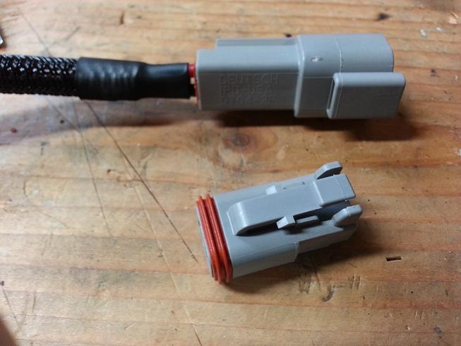
The Chassis is a 82 S (S2 base), which is, I believe the lightest Rx7 ever available, even against SA's. I am going for a minimalist, but functional look on everything in the car. Wiring will be visible, but very minimal; with Summit Racing lack nylon braid sheath over anything visible. All ends will be finished with a small piece of shink tube and a Deutsch connector. Things are both very complex and very simple in design and function. Its amazing how difficult it can be to make things look basic. This will make sense when the engine wiring comes together.
We attempt these things, not because they are easy, but because they are hard.

Junior Member
Joined: Apr 2013
Posts: 29
Likes: 0
From: SoCal
i am very impressed. you have a lot of patience and i take it you enjoy doing this as well  . i have a bunch of dead circuits as well from a choppy alarm system install and choppy stereo system install 2 owners prior, and wanted to get an unmodified wire harness ***'y but that is way too big a job for me. will slowly go through and clean up the wires under the instead.
. i have a bunch of dead circuits as well from a choppy alarm system install and choppy stereo system install 2 owners prior, and wanted to get an unmodified wire harness ***'y but that is way too big a job for me. will slowly go through and clean up the wires under the instead.
Mainly because there was a LOT of dead circuits, either disconnected, bypassed for increased amperage, or for an equipment option I don't have.
The Chassis is a 82 S (S2 base), which is, I believe the lightest Rx7 ever available, even against SA's. I am going for a minimalist, but functional look on everything in the car. Wiring will be visible, but very minimal; with Summit Racing lack nylon braid sheath over anything visible. All ends will be finished with a small piece of shink tube and a Deutsch connector. Things are both very complex and very simple in design and function. Its amazing how difficult it can be to make things look basic. This will make sense when the engine wiring comes together.
We attempt these things, not because they are easy, but because they are hard.
Sounds good. I understand. I also did a minimalist approach to the wiring on my FB race car. Mine was really simple.... I ripped everything out and made my own wiring harness. Luckily since it is a race car, all I really needed was wiring for the engine, fuel pumps, rear tail lights, fuel door opener, and fuel level.
Thread Starter
Joined: Jan 2002
Posts: 2,397
Likes: 1
From: Mound, MN
Got some time in on the wiring today; weather was excellent, despite the forecast. Hope the snow if ******* done; I love MN, but this **** is getting ridiculous.
Double checked things for the last time and started soldering everything together. I am a bit anxious about the wire gauge for things like the running lights and turn signals. The mazda stuff is MUCH smaller than the kit, but I imagine this is to handle oldschool fullsize GMs that had taillight assemblies that could be seen from space. Additionaly, it is set up for a combo brake/turn, whereas we have a divorced light. I am also considering LED bulbs if I can find turn and hazard flashers that will work on this kit.
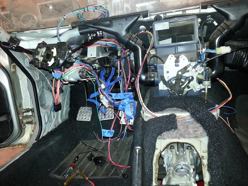
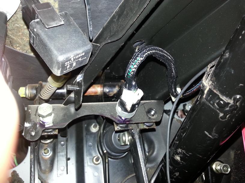
here's some of the finished work on the column. I got the turn, hazard, brake, hi/low beam out and horn circuits finished. I also got the wiper/washer switches hooked back up and ran circuits for the washer pump, but didn't hook it up. Intermittent is not hooked up, and I know that low and high speed with function. What I don't know is if the wiper arms will "Park" properly when I shut them off, they may stop mid sweep.
here's a quick shot of the only truly finished part of the harness. Finished the brake switch, fit it with the sheath and attached the harness clip. I love how this braid cover looks, and it will be clean when the engine harness is all finished and loomed.
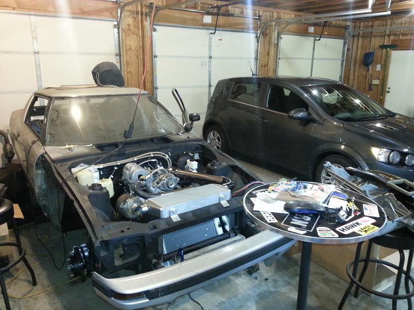
And the car and my Daily Beater, a 12 Chevy Sonic Turbo 1LT with turbo-back exhaust, DDM works intake and Trifecta tune. 20psi, around 175whp, and 43 mpg. I've also recalibrated the electric steering and traction modules with 2013 Sonic RS calibrations (perk of specializing in this stuff). Awesome little car for the price (I will have paid a bit less of course), highly recommended if you are in the market
Double checked things for the last time and started soldering everything together. I am a bit anxious about the wire gauge for things like the running lights and turn signals. The mazda stuff is MUCH smaller than the kit, but I imagine this is to handle oldschool fullsize GMs that had taillight assemblies that could be seen from space. Additionaly, it is set up for a combo brake/turn, whereas we have a divorced light. I am also considering LED bulbs if I can find turn and hazard flashers that will work on this kit.
here's some of the finished work on the column. I got the turn, hazard, brake, hi/low beam out and horn circuits finished. I also got the wiper/washer switches hooked back up and ran circuits for the washer pump, but didn't hook it up. Intermittent is not hooked up, and I know that low and high speed with function. What I don't know is if the wiper arms will "Park" properly when I shut them off, they may stop mid sweep.
here's a quick shot of the only truly finished part of the harness. Finished the brake switch, fit it with the sheath and attached the harness clip. I love how this braid cover looks, and it will be clean when the engine harness is all finished and loomed.
And the car and my Daily Beater, a 12 Chevy Sonic Turbo 1LT with turbo-back exhaust, DDM works intake and Trifecta tune. 20psi, around 175whp, and 43 mpg. I've also recalibrated the electric steering and traction modules with 2013 Sonic RS calibrations (perk of specializing in this stuff). Awesome little car for the price (I will have paid a bit less of course), highly recommended if you are in the market
Thread Starter
Joined: Jan 2002
Posts: 2,397
Likes: 1
From: Mound, MN
finished most of the column work. Still need to tie headlight power, but no big deal. Wiring is all but done, still needs final looming and covering.
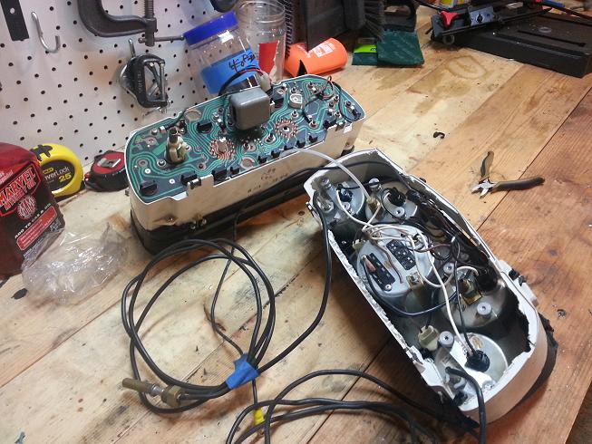
I decided to double check the ignition switch circuits before I soldered them in. When I checked it with a ohmmeter, it was way over spec. I brought it to work and pulled it apart. Lots of carbon, nothing a bit of emery cloth and some contact cleaner couldn't fix. This is an easy fix for anyone with a ignition switch issue, just be carefull when you remove the cover, there are lots of little springs in there.
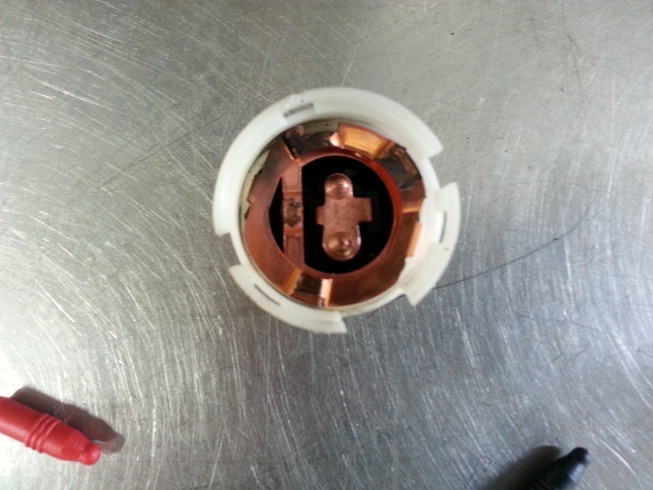
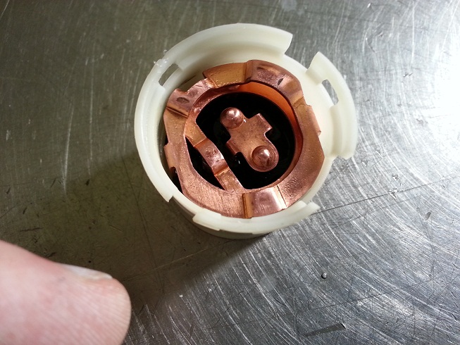
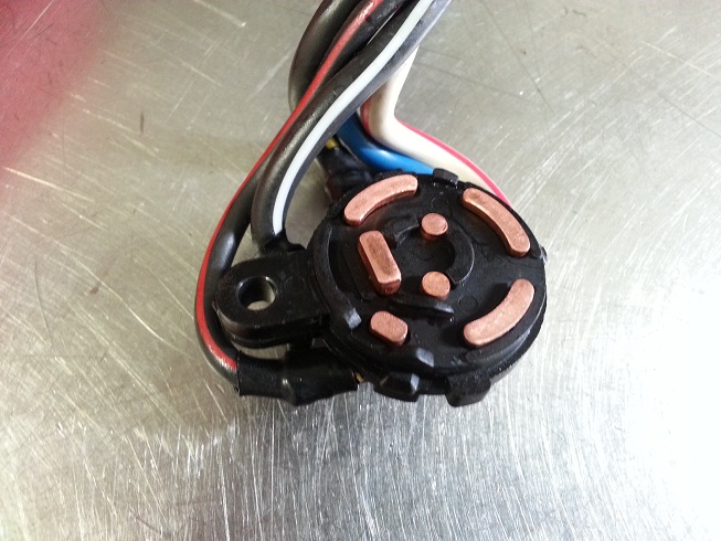
I decided to double check the ignition switch circuits before I soldered them in. When I checked it with a ohmmeter, it was way over spec. I brought it to work and pulled it apart. Lots of carbon, nothing a bit of emery cloth and some contact cleaner couldn't fix. This is an easy fix for anyone with a ignition switch issue, just be carefull when you remove the cover, there are lots of little springs in there.
Thread Starter
Joined: Jan 2002
Posts: 2,397
Likes: 1
From: Mound, MN
Weather has been insane again. It got a 100 here yesterday (MN), record. Luckily, it was pretty dry and wasn't too intense, except for all the fires that popped up. But I have been getting some time in on the car and have made some decent progress on the electrical work.
I decided to lump the Haltech install in this thread rather than start a new one, as this one did not get as huge as expected.
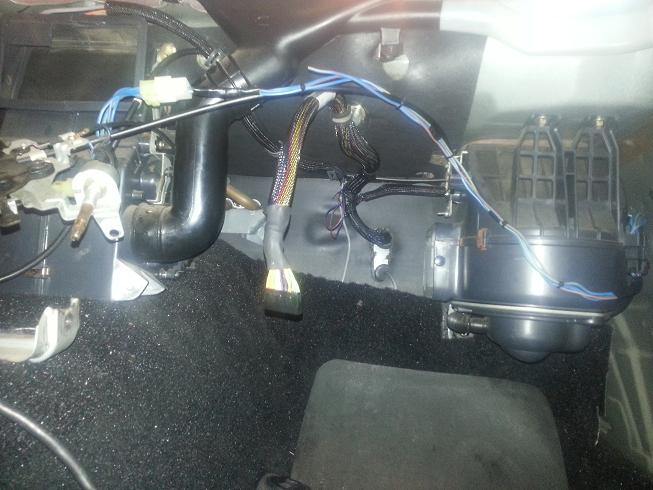
My final mounting decision on the haltech is the glovebox. Either on the inside or the outside, it will mount to the backside of glovebox. Likely on the inside because it will look cooler. Just went from there and started running wires to there general location. The pic currently shows the remaining bulk of wiring going to the center console area, but this will likely get changed.
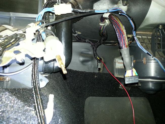
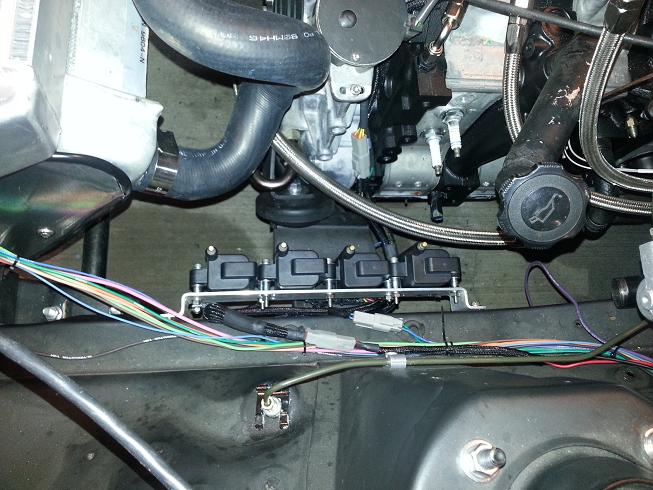
I routed the engine bay side of it through the A/C low-side port in the firewall, and over to the engine. The wideband harness will run though the highside port. Its secured to the block with a semi-floating mounting tab. From there it separates out to the various sensors and the injector and coil assemblies.
Thanks again to C. Ludwig for hooking me up on the Haltech Sprint RE, and making easy availability of specific connector kits for the injectors and the CAS. Having the CAS connector kit really allowed for the proper assembly of the harness and the clean/factory look I'm going for.
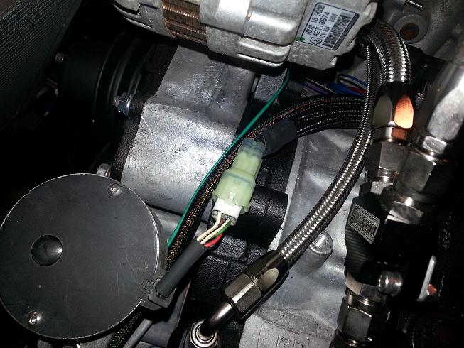
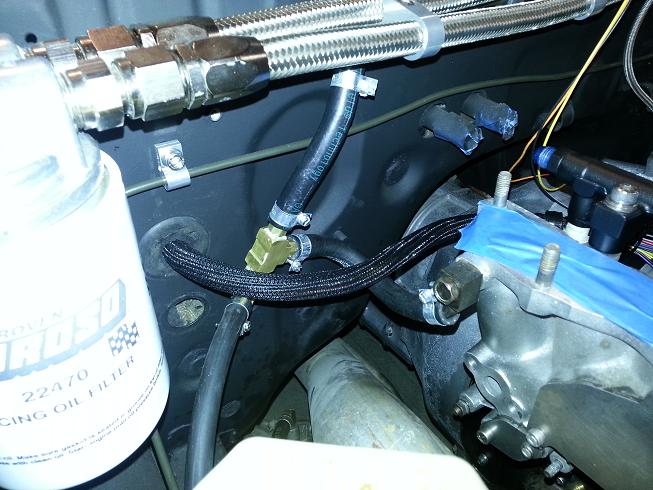
I also took a quick shot of a finished section of the harness with the Deutsch connector, braid and shrink. This is specifically the power/ground for the coil assm. These connectors are super easy to work with and look way cooler than the GM weatherpacks. highly recommend. Working automotive electrical, I wish every connector I had to deal with was like these.
Please comment/suggest/question
I decided to lump the Haltech install in this thread rather than start a new one, as this one did not get as huge as expected.
My final mounting decision on the haltech is the glovebox. Either on the inside or the outside, it will mount to the backside of glovebox. Likely on the inside because it will look cooler. Just went from there and started running wires to there general location. The pic currently shows the remaining bulk of wiring going to the center console area, but this will likely get changed.
I routed the engine bay side of it through the A/C low-side port in the firewall, and over to the engine. The wideband harness will run though the highside port. Its secured to the block with a semi-floating mounting tab. From there it separates out to the various sensors and the injector and coil assemblies.
Thanks again to C. Ludwig for hooking me up on the Haltech Sprint RE, and making easy availability of specific connector kits for the injectors and the CAS. Having the CAS connector kit really allowed for the proper assembly of the harness and the clean/factory look I'm going for.
I also took a quick shot of a finished section of the harness with the Deutsch connector, braid and shrink. This is specifically the power/ground for the coil assm. These connectors are super easy to work with and look way cooler than the GM weatherpacks. highly recommend. Working automotive electrical, I wish every connector I had to deal with was like these.
Please comment/suggest/question
Thread Starter
Joined: Jan 2002
Posts: 2,397
Likes: 1
From: Mound, MN
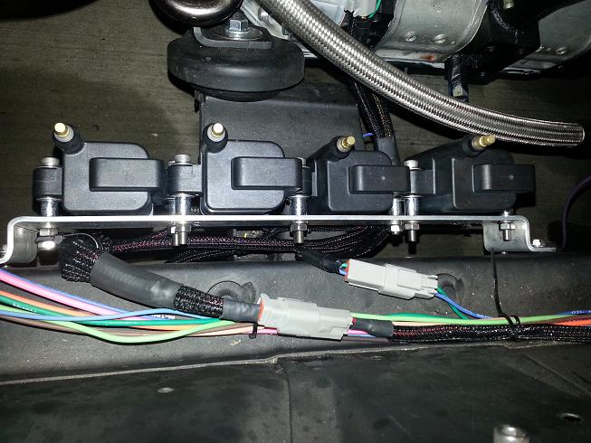
Got the coil harness built and more haltech circuits finished. Just need to crimp and connect the coil's chassis and rotor housing grounds. I didn't have the eyelets I needed on hand. It took forever because I'm **** on my electrical. For instance, Rotor 1 coils ground to the 1st rotor housing, chassis and battery grounds are separate. Main power and ground is 14ga direct to battery.
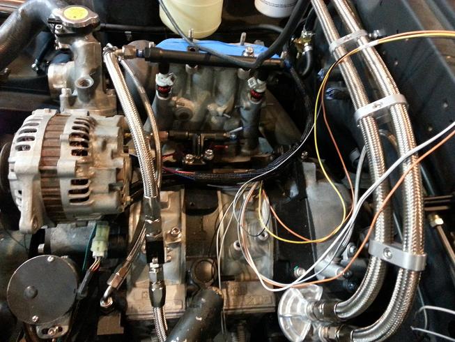
Here's the Main part of the haltech Harness, Still need to run the Air Temp and Injectors (waiting on Resistors for 1680 Secondarys). Also the connector running the ignition signals and water temp to the coil assembly and chassis.
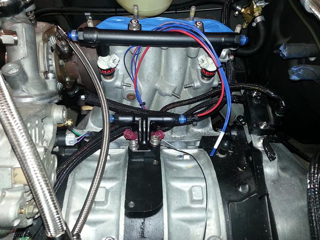
The coil assembly wiring proved to be challenging. 20 Circuits in packs of 5 going every which way made for difficult looming. Getting a clean look was time consuming and I still need to tidy up a few things. Overall I am pleased with the outcome and look. The engine bay harness still needs to be finished and loomed, and things will clean up further. I also ran a connector and loomed in the oil and water temp circuits.
Here's the Main part of the haltech Harness, Still need to run the Air Temp and Injectors (waiting on Resistors for 1680 Secondarys). Also the connector running the ignition signals and water temp to the coil assembly and chassis.
The coil assembly wiring proved to be challenging. 20 Circuits in packs of 5 going every which way made for difficult looming. Getting a clean look was time consuming and I still need to tidy up a few things. Overall I am pleased with the outcome and look. The engine bay harness still needs to be finished and loomed, and things will clean up further. I also ran a connector and loomed in the oil and water temp circuits.
Thread Starter
Joined: Jan 2002
Posts: 2,397
Likes: 1
From: Mound, MN
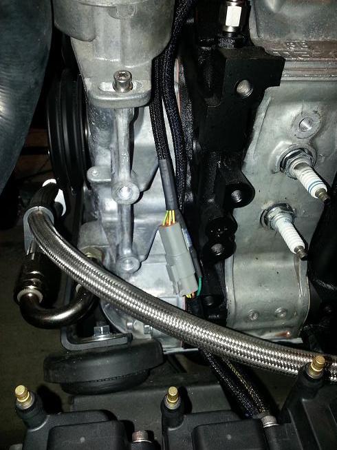
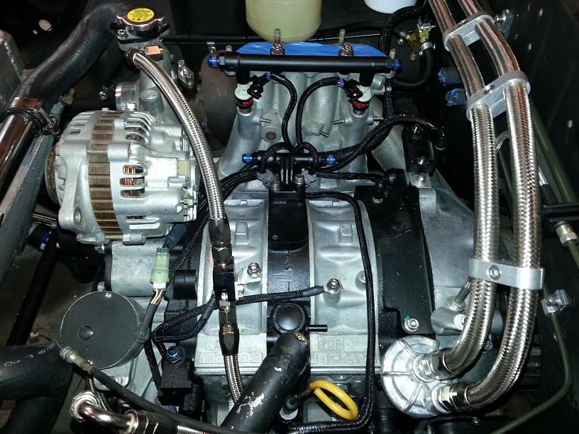
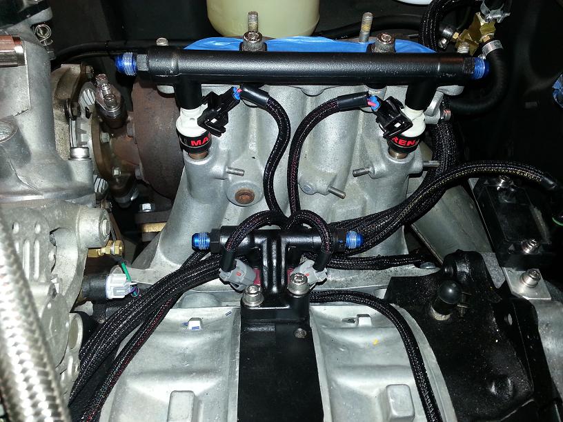
Finished the engine bay wiring of the haltech harness, short of the air temp connector, as I'm waiting on a part. Also finished the Coil grounds. Tricky routing again, but went smoothly.

Thread Starter
Joined: Jan 2002
Posts: 2,397
Likes: 1
From: Mound, MN
Thanks guys!!! I'm hoping to have it starting here in a week or two. But it may be a while before its on the Road. Maybe not till next spring. One of the reasons I've been busting *** on this lately is that I have my first child on the way, due in 6 weeks. After that, we'll see how much time I have to work on the car.
But my goal is to have it driving by Aug, to attend a large car show that is held at the Chevy dealership I work at.
Next step is to run the Wideband harness and start putting together the gauge clusters.
But my goal is to have it driving by Aug, to attend a large car show that is held at the Chevy dealership I work at.
Next step is to run the Wideband harness and start putting together the gauge clusters.
Thread Starter
Joined: Jan 2002
Posts: 2,397
Likes: 1
From: Mound, MN
Not really wiring related, besides needing to find a O2 location; but I got the exhaust wrapped this weekend.
Downpipe was cake, took about 30min, nothing too special here. Clearing the wideband bung worked out well.
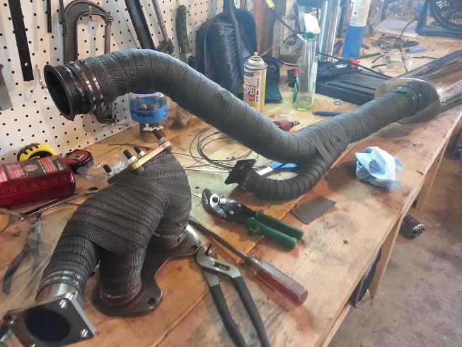
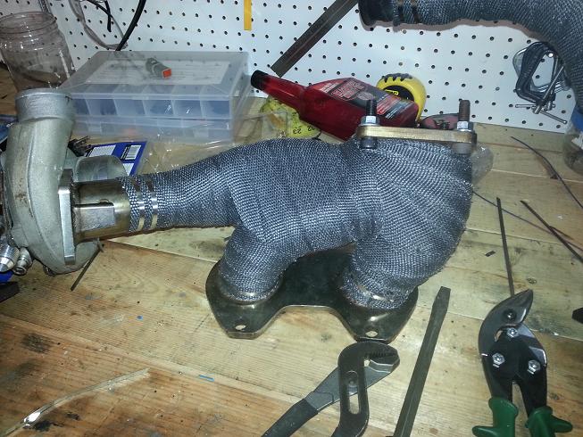
THe turbo manifold was a completely other story and took me all ******* day yesterday. The picture here is the third attempt and the best looking in my opinion.
Still, due to its tight design, parts of it are over wrapped a few times. I still may yet pull it apart again and try and do part of it in the 2in to get a more even coverage.
Both the manifold and downpipe still need to get sprayed with a black sealant which will darken them alot.
Downpipe was cake, took about 30min, nothing too special here. Clearing the wideband bung worked out well.
THe turbo manifold was a completely other story and took me all ******* day yesterday. The picture here is the third attempt and the best looking in my opinion.
Still, due to its tight design, parts of it are over wrapped a few times. I still may yet pull it apart again and try and do part of it in the 2in to get a more even coverage.
Both the manifold and downpipe still need to get sprayed with a black sealant which will darken them alot.
Thread Starter
Joined: Jan 2002
Posts: 2,397
Likes: 1
From: Mound, MN
Thanks, I do take pride in my electrical work. Its definitely something you cant half-***, or it will bite you in yours later.
Its been about a month and progress is good, got some more time in this afternoon. Haltech wiring for the engine is done, and the chassis parts of it are loomed and routed but not connected.
Chassis wiring for the dash is nearing completion for the dash section. Nothing is connected yet except for the column, but the looming is mainly finished. Maybe got 2 or 3 circuits I need to route (Laptop power and other random crap). I am also planning on pre-wiring for a headunit and multi-channel amp. Nothing too crazy is planned, but it will be quality. I'm just going to run signal and speaker wire for now so a stereo install is cake later.
And I got a teaser for the cool **** thats coming up. Next step is to start rebuilding the cluster and center console. Boxes from summit racing are like present on christmas morning
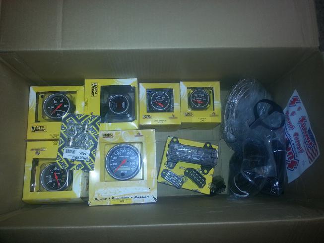
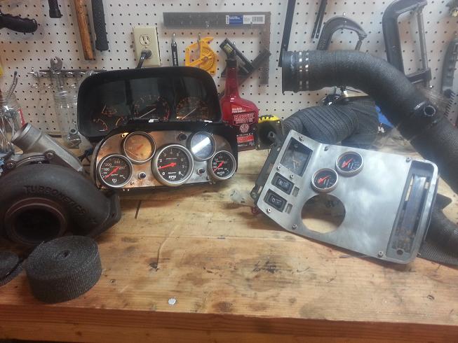
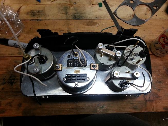
Here's a shot of the old setup. The list goes on, on why it needs to be redone. Mainly its cuz I built all this when I was 17 (28 now) and I used mild steel and it RUSTED. Its honestly got a cool patina, but I also trimmed the gauges to fit and they fogged up a result. The case cracked when I was drilling it and is held together with a grip of zip-ties. Its also mechanical temp gauges that have long sender cables (a pain in the *** to deal with).
Anyways, this will all be redone in Aluminum, with a slightly new gauge layout. I'm also now considering moving the oil pressure out with the fuel pressure gauge on the cowl (hard to see in the second pic). Its a mechanical and I'm worried about it leaking at some point. Plus another carbon fiber gauge cup and stainless line would look cool. I'm also losing the clock and factory switches. I will likely have manual override for fuel pump and electric fan. I wanted to do a matching Auto-meter Sport-comp clock, but its only available in the larger 2-5/8 size, which I think would look goofy. I am exploring other options for an analog clock, which I wish to keep in some form for nostalgia.
Props to Kaaarl12a for hooking me up with a new gauge cluster to work with, hopefully I don't crack this one.
Its been about a month and progress is good, got some more time in this afternoon. Haltech wiring for the engine is done, and the chassis parts of it are loomed and routed but not connected.
Chassis wiring for the dash is nearing completion for the dash section. Nothing is connected yet except for the column, but the looming is mainly finished. Maybe got 2 or 3 circuits I need to route (Laptop power and other random crap). I am also planning on pre-wiring for a headunit and multi-channel amp. Nothing too crazy is planned, but it will be quality. I'm just going to run signal and speaker wire for now so a stereo install is cake later.
And I got a teaser for the cool **** thats coming up. Next step is to start rebuilding the cluster and center console. Boxes from summit racing are like present on christmas morning
Here's a shot of the old setup. The list goes on, on why it needs to be redone. Mainly its cuz I built all this when I was 17 (28 now) and I used mild steel and it RUSTED. Its honestly got a cool patina, but I also trimmed the gauges to fit and they fogged up a result. The case cracked when I was drilling it and is held together with a grip of zip-ties. Its also mechanical temp gauges that have long sender cables (a pain in the *** to deal with).
Anyways, this will all be redone in Aluminum, with a slightly new gauge layout. I'm also now considering moving the oil pressure out with the fuel pressure gauge on the cowl (hard to see in the second pic). Its a mechanical and I'm worried about it leaking at some point. Plus another carbon fiber gauge cup and stainless line would look cool. I'm also losing the clock and factory switches. I will likely have manual override for fuel pump and electric fan. I wanted to do a matching Auto-meter Sport-comp clock, but its only available in the larger 2-5/8 size, which I think would look goofy. I am exploring other options for an analog clock, which I wish to keep in some form for nostalgia.
Props to Kaaarl12a for hooking me up with a new gauge cluster to work with, hopefully I don't crack this one.
Stock ign switch and setup is terrible. I burnt up a new switch in a few months! Cleaned the old one, and made the switch a ground trigger for relays for all the hot circuits. Been that way for like 2 years now and works great. FWIW.
Looking damn good! Huge undertaking!
Looking damn good! Huge undertaking!
Thread Starter
Joined: Jan 2002
Posts: 2,397
Likes: 1
From: Mound, MN
Started work on the gauge redo; its amazing looking back at the way I put things together when I was kid. The old setup is super ghetto, but I think it is an even mix of both inexperience and almost no resources, some real mad-max ****. When it was installed, it looked pretty decent. But removed, it was a real ******* mess.
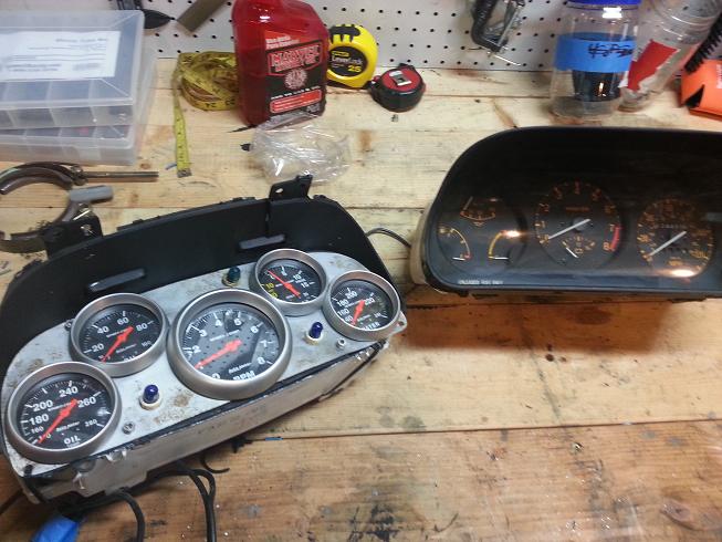
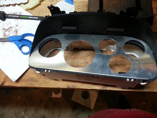
Got the new plate cut out, quick work compared to the first time I did it. I also made the design change (in my mental master plan) of moving the oil pressure gauge to the cowl with fuel press gauge. I did this mainly because its a mechanical fluid pressure gauge (for full sweep without costing a fortune). Not perfectly safe to run a signal line into the cabin without an isolator. I also thing that two gauges will look much better than one.This will also allow me to keep all important gauges in direct drivers view. Originally oil temp would have been on the console.
I'm just checking fit here, but the layout left to right will be: Boost/Vac, Tacho, Water Temp, A/F ratio, Oil temp. The center console: Volt, Fuel level, speedo. THis is the same general layout I used before, and I always got asked on the placement of the speedo way over in the console; Its because its required, but the least important one of the 10 Gauges.
Last edited by 82streetracer; Jun 4, 2013 at 10:05 PM. Reason: Grammer


Thread Starter
Joined: Jan 2002
Posts: 2,397
Likes: 1
From: Mound, MN
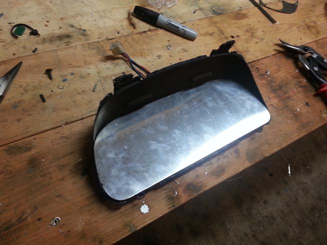
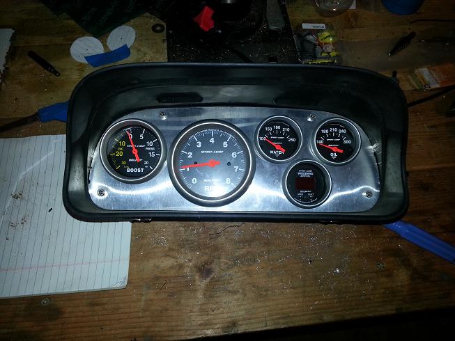
Got the cluster fabrication finished today, still need to wire it. Im pretty happy how it turned out. I trimmed out the factory shell with a bone-saw, cutting back all but the last quarter inch or so. Attached the empty face plate and cut that back a bit, left some area for attachment hardware. I drilled the holes in the sheet metal by clamping it on the drill-press between some hole-board and drilling with a hole saw. It worked beautifully, the hole-board allowed me to sight the bit and get it perfect.
Once I had that cut, I used the trip-reset hole as the first mount and matched it on the other side. The top ones are drilled on a set of matching casting marks, cuts way down on the measuring to get things straight. Had to do some minor trimming on the gauge mount cups, but nothing crazy. Should look and fit a lot tighter than it did, center console starts tomorrow.
Once I had that cut, I used the trip-reset hole as the first mount and matched it on the other side. The top ones are drilled on a set of matching casting marks, cuts way down on the measuring to get things straight. Had to do some minor trimming on the gauge mount cups, but nothing crazy. Should look and fit a lot tighter than it did, center console starts tomorrow.