
Transistor trick for 2GCDFIS.

Rotary Enthusiast
Joined: Aug 2004
Posts: 1,100
Likes: 0
From: The World
hmm i just recieved kents coilpack and think i rewired mine (as seen in photos above) the wrong way.. there is a chance my ignitor still works. i have to race off to work now but will look into this on the weekend 
Just in case you didnt know a there are two different versions of the coil pack so there are 2 different ways to wiring them according to wich one you have. So you may have your right depending on what you have.
Rotary Enthusiast
Joined: Aug 2004
Posts: 1,100
Likes: 0
From: The World
ahhh that could be it!! yeah checking back over my original photos, i did wire it up correctly. although i am questioning whether i wired up the ignition signal pulse to my fuel injection ecu... might give it another shot on the weekend
Rotary Enthusiast
Joined: Aug 2004
Posts: 1,100
Likes: 0
From: The World
Something interesting I noted today on both my car and Robs.
Notes:
- I am using Kent's coilpack in it's stock form on the TT circuit.
- Rob is using a coilpack which he has modded with some resistors, on the TT circuit.
With my timing light, on the front rotor output, it flashes pretty fast (I think twice as fast as it should be).
On the rear rotor it is flashing at half the speed of the front rotor...
I don't know if this is the timing light or what, but it happens the same on both Rob and my cars with these slightly different setups- we first noticed it on Rob's and were going to blame some problems on it but we soon found my car did this too with an unmodified coilpack.
Any ideas? Rob is going to post up details on his specific issues, but heres somethign to get started on
Cheers,
Paul.
Junior Member
Joined: Sep 2004
Posts: 7
Likes: 0
From: Melbourne
Hi Everyone,
Today I decided to try another approach to dealing with the heat issue of the simple TT. As others have mentioned, it would seem that the best strategy would be to relocate the source of heat (resistor) away from the coil pack. I use a 1/8th in. steel bracket to mount the coil pack from the strut tower. There was a gap between the bracket underside and the strut tower which provided sufficient clearance to fit a megachunk aluminium heatsink. I bolted the heatsink to the bracket. Then I removed the stock 0.35ohm 5W resistor from the ignitor housing and ran the wire externally to two 1.0ohm 10W resistors wedged tightly into the heatsink with silver thermal paste (of course being careful not to short anything). The resistors were setup in parallel to give 0.5ohm. The wire was 16gauge i think, but due to its length some resistance was apparent (measured a total of 0.9ohm).
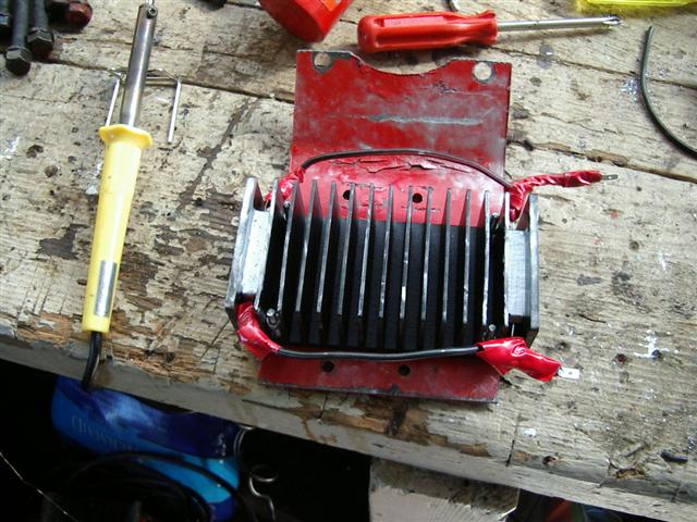
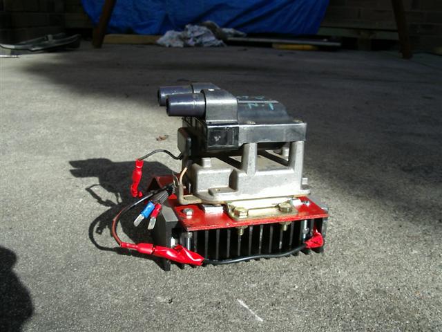
When i started her, the idle was down to 500rpm from the usual ~800rpm. Paul came round with a timing light and we found the timing to be spot on. The leadings were firing, but the throttle responsiveness and power were down. It was worse than stock ignition. I suspect that the higher resistance i.e. 0.9 vs. ~0.4ohm may be the cause. However, after 5mins of idling, the heatsink was only slightly warm so an improvement in that department.
I will persevere. The transformation in the car (stock 12a, modified Nikki) is substantial. Compared to the stock ignition, the car idles better, smoother, there seems to be more power at all rpm, and the engine is alot more 'eager'. The best analogy i can offer to those who havent tried the TT: its like putting a set of new plugs in your car everytime you drive it. Pretty great
Today I decided to try another approach to dealing with the heat issue of the simple TT. As others have mentioned, it would seem that the best strategy would be to relocate the source of heat (resistor) away from the coil pack. I use a 1/8th in. steel bracket to mount the coil pack from the strut tower. There was a gap between the bracket underside and the strut tower which provided sufficient clearance to fit a megachunk aluminium heatsink. I bolted the heatsink to the bracket. Then I removed the stock 0.35ohm 5W resistor from the ignitor housing and ran the wire externally to two 1.0ohm 10W resistors wedged tightly into the heatsink with silver thermal paste (of course being careful not to short anything). The resistors were setup in parallel to give 0.5ohm. The wire was 16gauge i think, but due to its length some resistance was apparent (measured a total of 0.9ohm).
When i started her, the idle was down to 500rpm from the usual ~800rpm. Paul came round with a timing light and we found the timing to be spot on. The leadings were firing, but the throttle responsiveness and power were down. It was worse than stock ignition. I suspect that the higher resistance i.e. 0.9 vs. ~0.4ohm may be the cause. However, after 5mins of idling, the heatsink was only slightly warm so an improvement in that department.
I will persevere. The transformation in the car (stock 12a, modified Nikki) is substantial. Compared to the stock ignition, the car idles better, smoother, there seems to be more power at all rpm, and the engine is alot more 'eager'. The best analogy i can offer to those who havent tried the TT: its like putting a set of new plugs in your car everytime you drive it. Pretty great
Lives on the Forum
Joined: Jun 2004
Posts: 11,359
Likes: 14
From: Grand Rapids Michigan
Originally Posted by H4Inf
Something interesting I noted today on both my car and Robs.
Notes:
- I am using Kent's coilpack in it's stock form on the TT circuit.
- Rob is using a coilpack which he has modded with some resistors, on the TT circuit.
With my timing light, on the front rotor output, it flashes pretty fast (I think twice as fast as it should be).
On the rear rotor it is flashing at half the speed of the front rotor...
I don't know if this is the timing light or what, but it happens the same on both Rob and my cars with these slightly different setups- we first noticed it on Rob's and were going to blame some problems on it but we soon found my car did this too with an unmodified coilpack.
Any ideas? Rob is going to post up details on his specific issues, but heres somethign to get started on
Cheers,
Paul.
Notes:
- I am using Kent's coilpack in it's stock form on the TT circuit.
- Rob is using a coilpack which he has modded with some resistors, on the TT circuit.
With my timing light, on the front rotor output, it flashes pretty fast (I think twice as fast as it should be).
On the rear rotor it is flashing at half the speed of the front rotor...
I don't know if this is the timing light or what, but it happens the same on both Rob and my cars with these slightly different setups- we first noticed it on Rob's and were going to blame some problems on it but we soon found my car did this too with an unmodified coilpack.
Any ideas? Rob is going to post up details on his specific issues, but heres somethign to get started on
Cheers,
Paul.
Rotary Enthusiast
Joined: Aug 2004
Posts: 1,100
Likes: 0
From: The World
Originally Posted by Kentetsu
Paul. I believe that what you are seeing is the "wasted spark", meaning that each leading plug will fire twice per "cycle". Normally, the spark would be split by the distributor cap, but since the direct fire eliminates the cap, you get an extra spark. Nothing to worry about, this is normal.
so:
Leading Rotor 1 at 500rpm is firing 1000 times per minute
Leading Rotor 2 at 500rpm is firing 500 times per minute
You can see it clearly, the difference between the speeds of flickering of the timing light, at low rpm.
Odd one eh
Weird deal. I am not sure what would cause the difference between the front/rear like that. Good work on the resistor testing, Rob. It is the kind of thing we need to mess with. It sounds like the 0.5 ohm extra may be too much. Perhaps the easiest to try is to short the 0.35 stock resistor so the total is 0.5 Ohm and see how that does. Perhaps a bit heavier wire would help as well. In current limiting mode, the current draw is about 7.5 amps. Just to give you an idea for the wire size.
For me, my car is non-operational at the moment. I got it shipped back here to VA, but the day it was picked up, the fuel pump started acting up. It quits even with power to it. Hit it with something and it sometimes starts to work again. Anyway, I am trying to get a fuel pump and try to find a time to put it on (apatment complex doesn't allow car repair, I need to be sneaky ) I will do much like Rob is doing with different resistances. It is the easiest potential solution to the problem.
Kent
For me, my car is non-operational at the moment. I got it shipped back here to VA, but the day it was picked up, the fuel pump started acting up. It quits even with power to it. Hit it with something and it sometimes starts to work again. Anyway, I am trying to get a fuel pump and try to find a time to put it on (apatment complex doesn't allow car repair, I need to be sneaky
) I will do much like Rob is doing with different resistances. It is the easiest potential solution to the problem.Kent

Full Member
Joined: Oct 2005
Posts: 53
Likes: 0
From: Tucson, AZ
Ok, well after tearing apart 3 cas�s and 2 dizzy�s I think I have come up with something worth putting on my engine. Direct fire leading and trailing with a waste on the leading (for the fans of waste spark), an adjustable trailing split from 0 - max desired degrees and mechanical timing. Oh and it all fits somewhat in a cas just need a custom cap made. Or if you wanted to you could wire it up in a way to fire leading and trailing at the same time then again at any given split.
Just a prototype and looks a little rough but will work.
Just a prototype and looks a little rough but will work.
Sounds interesting. You probably need to reduce the pic size in order to upload. I think the size limit is like 125k or so. Are to trying to fire 2nd gen coils with ignitors with this setup or are you using 1st gen ignitors/coils?
As for me, I got the new fuel pump for my car, but found out I needed to get a routine surgery performed. Anyway, I am laid up right now, but am getting better. I hope to be well enough in a week or 2 to get the pump on and get back to doing some testing.
As for me, I got the new fuel pump for my car, but found out I needed to get a routine surgery performed. Anyway, I am laid up right now, but am getting better. I hope to be well enough in a week or 2 to get the pump on and get back to doing some testing.

Full Member
Joined: May 2005
Posts: 156
Likes: 0
From: geneva, il
hey i have been out of the loop for a while. i was wondering if there were any of the prefabbed kits still for sale? if so can someone email me at jmilton1987@gmail.com with more info
Sorry about the lack of updates. Been busy with some other stuff. I do have some promising news. I was talking with aws140, and he mentioned how someone had posted that they have ran a year without any ignitor failures. That person is bad 83 (Sam). I recommended to Sam while I was in France to try 4 10W, 10 Ohm resistors in parallel. This adds a resistance of 2.5 Ohm. I didn't hear if he had actually tried it our not until now. He has ran for about 1 year without problems. He added his on the coil power wire. He will be sending me a pic, so I know the exact was it is wired. If it is on the incoming tan wire (12 v), there may be some issue has the voltage at the ignitor will drop each time the coil charges. Not sure if this matters or not. Probably a better method would be to replace the stock ballast or otherwise put the resistor in the circuit between the ignitor and the coil.
One thing we need to know is performance. Rob in Australlia tested adding 0.5 Ohms (two 1 Ohm resistors in parallel). Results on previous page of this thread (page 77 at bottom). He noticed decreased idle and slower response. So it would seem that Sam's setup would have even worse response. He is running a blow-through setup, so it may be hard to compare.
It still seems the extra resistance is the easiest way to extend ignitor life. The question is what is optimum. Can anyone help with the testing? I have circuits available for those who help test, but don't have a TT circuit. I will see what Sam's setup is and let you guys know.
Ideally, it would be nice to get a drop-in replacement for the stock ballast resistor if possible. Just remove the old and solder in the new. I have found resistors in the correct style, but they don't appear to come with the metal mounting tab. I will keep searching.
Kent
The resistor that you are speaking of (the stock one) I 'm thinking that I elimanted that one on the second gen coil. I still have the one on the dizzy. I wired the curcuit per the diagram in the archive. Then I added 10 watt 10 ohm resistors where the power goes into the second gen coil. See drawing. I haven't noticed any decrease in power or performance.

Full Member
Joined: Oct 2005
Posts: 53
Likes: 0
From: Tucson, AZ
I can help with testing, I will be running two motors at once so it is posible to do some side by side testing, let me know. jeff.hardin@gmail.com
Time to bring this to the top again.
I'm about to install my original version TT I am thinking that I will replace the ballast resistor in the coil pack with 3 - 10 W 1 ohm resistors, giving 0.33 ohm against the original 0.39 ohm. What do you think?
RXDad
I'm about to install my original version TT I am thinking that I will replace the ballast resistor in the coil pack with 3 - 10 W 1 ohm resistors, giving 0.33 ohm against the original 0.39 ohm. What do you think?
RXDad
Lives on the Forum
Joined: Jun 2004
Posts: 11,359
Likes: 14
From: Grand Rapids Michigan
I don't believe you'll have any issues with either the original unit, or the one with the switch on it. Only the auto-switching unit is burning up the ignitors as far as I know...