
Transistor trick for 2GCDFIS.

Hey Kent & Paul,
If you guys can send me your emails I will send the pictures off to either of you or both doesn't really matter. But after opening up the ECU I really have no clue what part I should be focusing on. So I took some very general pictures at the moment. If you can give me more specific locations on the board to take pictures of I will do so.
-Alex
Last edited by Rx Seven; Jun 13, 2006 at 07:59 PM.
Rotary Enthusiast
Joined: Aug 2004
Posts: 1,100
Likes: 0
From: The World
Hi Alex,
You can email me at: paul@pw.cx
and I believe you can get Kent at: kent.abel@gmail.com
We'll have a look and try to work out what we're after
Cheers,
Paul.
You can email me at: paul@pw.cx
and I believe you can get Kent at: kent.abel@gmail.com
We'll have a look and try to work out what we're after
Cheers,
Paul.
callin' tokyo
Joined: Dec 2002
Posts: 1,353
Likes: 0
From: Windsor, Ontario
Got mine today. I've got company over for the weekend and I am also working, so I won't be able to put much time on this.
And to top it all off, the rear bearings just went, so that kills road tests
I'll start by hooking it all up and then I'll be working directly with Kent using Messenger.
And to top it all off, the rear bearings just went, so that kills road tests
I'll start by hooking it all up and then I'll be working directly with Kent using Messenger.
Lives on the Forum
Joined: Jun 2004
Posts: 11,359
Likes: 14
From: Grand Rapids Michigan
Got a new timing light for Father's day Made by Craftsman, its the nice stainless steel one with adjustable advance. So I figured I'd set my timing using the "racing beat" method. Revved and held it at 4k and hit it with the light, no mark visible which is expected. I started turning the advance **** and when I got up to around 24 the dot would start showing up once in a while, but nothing steady. Seems that she might be bouncing around at high rpms. I'll do some more checking tomorrow and post if I find anything definite.
Made by Craftsman, its the nice stainless steel one with adjustable advance. So I figured I'd set my timing using the "racing beat" method. Revved and held it at 4k and hit it with the light, no mark visible which is expected. I started turning the advance **** and when I got up to around 24 the dot would start showing up once in a while, but nothing steady. Seems that she might be bouncing around at high rpms. I'll do some more checking tomorrow and post if I find anything definite.
Okay. Just giving an update on testing. Dom has been running some tests and Paul/Rob have done a bit more testing as well. We first tried an optoisolator on the TT output. This is to electrically isolate the TT from the coil. Both Dom and Paul/Rob tried this with no improvement. Dom also tried connecting the output from the opto to a separate 7805 Vreg to totally isolate (didn't help, though). In order to really make sure noise from the 12v line wasn't getting in, Dom also tried running the TT and opto from a separate battery while the coil pack is powered by the car battery. Still the same problem (leading ignition retards).
So we know:
- problem not due to noise between TT output/Coil input
- not due to noise on the 12v line
So, it is noise that is causing the problem, it is either coming from the input (J-109) or on the ground line. We are also thinking that it could be a crosstalk issue. Crosstalk is when you have two traces running parralel and the signal in one trace induces a signal in the other. I haven't seen this, though. All of the signals appear to look good, but there seems to be a shift in all of them with the coil/R2 connected. This circuit seems to work fine, but on this incorrect input.
Dom is going to try to build the circuit with a different layout to see if it is the positioning of traces/parts that is causing the problem. I am also looking at a different way to connect the monostables for the max/min pulsewidth.
Alex is going to ship me his S5 ECU to study. We decided to wait to ship because I am moving this weekend. We didn't want the ECU to get delivered to the wrong address. I have my new address now and will give to Alex so that he can ship.
So, that if where we are at, currently. Dom may pick up an o-scope to aid in testing. We will continue to work on this until it is figured out. Thank you so much to all the guys helping with testing and for all the rest of you waiting patiently. If it is a layout problem (like crosstalk), I may have to have all the boards redone. It is expensive, but I will do whatever it takes to get these working for you guys. It is so hard to believe that such a simple circuit is causing so much difficulty.
Kent
Rotary Enthusiast
Joined: Aug 2004
Posts: 1,100
Likes: 0
From: The World
Hmm perhaps this noise is normal. The J109 grabs its earth from the engine block, and when the spark plugs spark, they are dumping a lot of voltage through to earth, so lessening the potential between the ground and +12v ?
Therefore this spike comes through into the J109.
Look at the stock ignition, it just recieves a pulse from the J109, and fires and its as simple as that.
Most Electronic spark systems will use a CAS, not the j109 type of sensor we are using - these run completely seperate to the engine ground dont they..
so maybe we should look at a cas kind of sensor to ensure a clean input signal into the TT.
it has been a long day and i came up with this in a few seconds so it could be completely wrong
Paul.

Rotary Enthusiast
Joined: Aug 2004
Posts: 1,100
Likes: 0
From: The World
Originally Posted by wackyracer
I say, use DLIDFIS. No headache.
Just my honest opinion.
Just my honest opinion.
DLIDFIS would have gone through a teething stage. Once TT is finished, its finished, and will be just as reliable and produce a better ignition result than DLIDFIS.We'll let you know when they are ready to ship. Cant produce something good without doing any work :P
Originally Posted by H4Inf
The TT is currently being developped so just you wait and see what we come up with DLIDFIS would have gone through a teething stage. Once TT is finished, its finished, and will be just as reliable and produce a better ignition result than DLIDFIS.
We'll let you know when they are ready to ship. Cant produce something good without doing any work :P
DLIDFIS would have gone through a teething stage. Once TT is finished, its finished, and will be just as reliable and produce a better ignition result than DLIDFIS.We'll let you know when they are ready to ship. Cant produce something good without doing any work :P
Really? Ok, when its done, send one to me for testing so I compare with:
DLIDFIS, MSD 6A/AL direct fire wtih blaster coils or FC leading coil.

callin' tokyo
Joined: Dec 2002
Posts: 1,353
Likes: 0
From: Windsor, Ontario
Picked up the scope today. Tested it, calibrated it, calibrated the probes. It's all good.
I have ordered the 4538, 7805 and the caps (I all ready have a stock of 7400). I am just waiting on them to process and ship.
I have ordered the 4538, 7805 and the caps (I all ready have a stock of 7400). I am just waiting on them to process and ship.


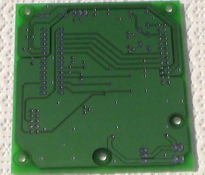
Hi guys, I've done a bit of PCB design, and would like to offer a few suggestions to the person who is designing/building the circuit boards:
1. Your circuit board is missing a ground plane. If cross-talk interference is truly the cause of your problems, a ground plane will eliminate this. Here are a few links for you:
PCB Design Tutorial (lots and lots of technical info):
http://www.alternatezone.com/electronics/pcbdesign.htm
Ground plane implementation (polygons using EAGLE software):
http://www.interq.or.jp/japan/se-inoue/e_eagle32.htm#1
This photo shows a circuit board with a ground plane, on the left side of the PCB:
http://members.lycos.nl/anthonyvh/im...allsup-pcb.jpg
Here is a photo of one of the first PCB's I designed: Both layers incorporate a ground plane that surrounds all traces. The top and bottom ground planes are connected every 1/4" or so, by a grid of 'stitching vias.'
2. Add decoupling capacitors (capacitor connecting Vcc to GND) for each of your digital chips. When a digital circuit switches on or off, it draws a lot of current for a short period of time, which can cause fluctuations in the supply voltage. Decoupling capacitors will supply this current without putting a strain on your power supply. Use two in parallel (try 0.1uF and 10uF) if you've got the space and budget.
3. Keep your high-current devices, if any, physically isolated from your low-current stuff. Keep high-current traces as wide and short as possible.
4. If those steps don't solve your noise issues, you might want to add a big (1000 uF) capacitor to smooth out the 12V line. It's possible that alternator noise is causing problems.
Good luck,
-s-
Thanks for the tips. The only reason I didn't use a ground plane is that the previous circuits (built by hand) seemed to operate correctly without one and I didn't want to make too many changes. I guess I should have. Hindsight is 20/20 as they say.
Dom has been testing and we have been discussing the results. It looks more and more like cross-talk, but I can't say for sure. If I know a board redesign will cure our troubles, I am up for it. It is an expensive solution, but may be the best route. I just want to be sure on the cause of the problem so that I will know if the board redesign will cure it. A redesign will allow us to have the mods built cleanly into the board and could add additional isolation (optoisolators) between the circuit and the input/output.
Kent
Well, guys. I think I have figured something out. Unfortunately, the problem is going to need a full board redesign to fix. I thought of this when talking to Dom about the operation of the TT. Here is the problem:
-Normally, the J-109 pulls the coil - (C terminal on the J-109) to ground when charging the coil
- When the J-109 releases this, the coil fires.
Now with the TT, the output goes high when the J-109 goes low (the charging of the 2nd gen coil begins just before this). Without a max limit, the signal goes low when J-109 goes back high (this fires the 2nd gen coil, same time as the 1st gen coil would have fired). So that part is cool. But... when we limit this pulse (to say 4ms), the coil fires too early. This seems like it would advance instead of retard. What is happening is that the advancing is so much, the marks are coming all the way around to the other side. For instance, Paul and Rob were seeing the J-109 go low for about 26ms. Now if we limit the output pulse to 4ms, the spark happens 22ms too early. At 1000 RPM, the normal spark happens at 60ms intervals with the late leading happening 30ms after each normal spark.
So what does this mean? With R2 is place, the timing is advanced by about 132* based on these numbers (why you can't see the mark sometimes). When the mark is seen, I believe you are seeing the late leading (or L2 spark). This would occur at 132*+180*=312*advance (or 48* retarded). These numbers are apporimate, but you get the idea. As RPMs increase, the pulse from the J-109 is closer to the 4ms value (J-109 decreases with RPM). This makes the error less (less advance), so the mark appear to retard.
So to fix this, we need the output from the TT to go low when the J-109 goes high. That in itself is no problem. The trick is to know how to start the coil charging a certain amount of time *before* this happens. I will see what I can come up with. I had a feeling that there was something that we were just missing. That something is the coil fires on the trailing edge of the pulse, so that is what needs to be in sync.
Thanks for all the help testing, guys. It seems that answer to problems come up when trying to explain the problem/issue to someone else. It makes you stedp back and really think about the fundementals. I will redesign the board and add in all the extra features. I will build/test a few prototypes and run off the final set. I am really sorry about the delay, but there was a problem and I will make sure it is corrected.
- Kent
Okay. I need some input from you guys. This is what I am thinking. For people who want a TT now, I can set you up with the current version at a reduced cost (without R2). I will figure out a ballast resistor you can add to to coil to reduce the heating problem.
The other option is to wait for a more advanced version. I am not sure how easy it is going to be to make this work with normal logic. This is because we need something to happen some amount of time before something else occurs. You have to predict when the J-109 will go back high. This may require a microcontroller. I kind of wanted to stay away from getting too advanced as the goal of this was to make a simple/cheap way of using the 2nd gen packs.
Anyway, let me know what you guys think. I will try my best to make the max pulse thing work without getting too fancy, but I am not sure if it is going to work.
Thanks,
Kent