
Transistor trick for 2GCDFIS.

Well, those two resistors that are mounted higher are that way for testing. He mounted like that so they are easier to remove if needed. In general, components that are mounted higher up are because of heat/power. By lifting the part off the board, air can circulate around the part to help keep it cool.

Paul: I will try to go out there again today and check again advancing and retarding. Its quite hard to tell I think. about bouncyness ... do you have yours hooked up with the stock coil still plugged in or not?
Rotary Enthusiast
Joined: Aug 2004
Posts: 1,100
Likes: 0
From: The World
Hi Sam,
It would be good to see what you can find - To answer your question, my stock coil is completely disconnected. I also see bouncyness but only a little..
I'm going to sleep now, but will be attacking this in the morning to see what I can find out
Cheers,
Paul.
It would be good to see what you can find - To answer your question, my stock coil is completely disconnected. I also see bouncyness but only a little..
I'm going to sleep now, but will be attacking this in the morning to see what I can find out
Cheers,
Paul.
alright ... but ya about the bouncyness i know what you're talking about, but removing the coil reduced it quite a bit from my setup. I wounder if we put a diode on the ground also to keep any noise coming to the board.
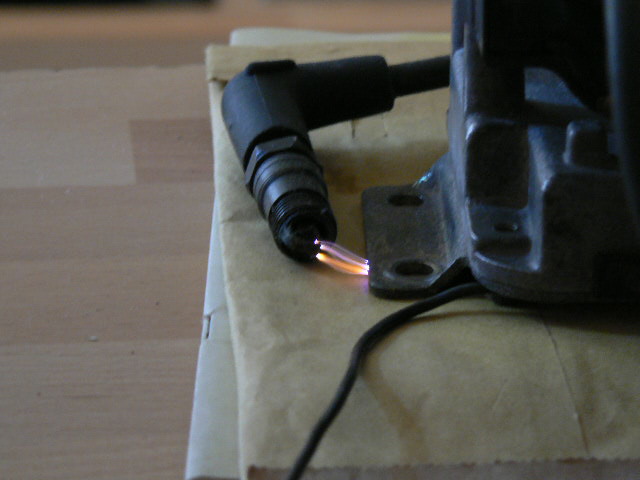
I took a couple pics of the sparks. It is a little hard because both output posts are connected together on the 2nd gen coil. This means that the spark will want to go through the side of less resistance. So you need to try to have both sides even for max spark length. I did burn a nice hole through the envelope that I had the coil setting on, though. 
If Sam can verify if his setup works correctly, Paul and I will get his board set up the same way. I will continue studying the circuit and testing and see if I can find anything. I will work with Paul again tomorrow and see what we can figure out.
- Kent
Edit: Yes, those are Autolites. They are not for my 7. My Dad couldn't find my old NGKs, so he sent some old ones from his Mazda pickup.
Last edited by gsl-se addict; Jun 10, 2006 at 01:02 PM.
Rotary Enthusiast
Joined: Aug 2004
Posts: 1,100
Likes: 0
From: The World
Right now I am running with 2x5.6k in place of R3 (in parallel).
Today I also added a diode between the TT board and grounding to the battery pointing out. This didn't make any difference.
I also tried running seperate power leads to the battery for the TT and the coil and this also made no difference, I couldnt get the car to even start this time (this is because the car was cold having been left overnight at close to freezing point outside, although having removed R2, she started up fine and ran well.. after all the blue smoke cleared)
So I am still thinking theres a problem somewhere, and its something to do with the way R2 is affecting surrounding components, or perhaps it is letting some noise through somewhere...
Basically the timing is about 30-40 degrees retarded when R2 is in place, and increasing RPM causes it to retard more, so it seems there is a fixed delay induced in the circuit, and as we increase the input pulse frequency, this fixed delay is multiplying to produce an output with more delay...
Waiting to hear back from Sam regarding his ignition advance/retard, if it is working as we hope then I'll try and replicate his setup here.
Cheers,
Paul.
Today I also added a diode between the TT board and grounding to the battery pointing out. This didn't make any difference.
I also tried running seperate power leads to the battery for the TT and the coil and this also made no difference, I couldnt get the car to even start this time (this is because the car was cold having been left overnight at close to freezing point outside, although having removed R2, she started up fine and ran well.. after all the blue smoke cleared
)So I am still thinking theres a problem somewhere, and its something to do with the way R2 is affecting surrounding components, or perhaps it is letting some noise through somewhere...
Basically the timing is about 30-40 degrees retarded when R2 is in place, and increasing RPM causes it to retard more, so it seems there is a fixed delay induced in the circuit, and as we increase the input pulse frequency, this fixed delay is multiplying to produce an output with more delay...
Waiting to hear back from Sam regarding his ignition advance/retard, if it is working as we hope then I'll try and replicate his setup here.
Cheers,
Paul.
Alright ... the Bad News ...
So i went outhere today with some assitance to make sure things are going the right way ... and guess what, before i was reving it too fast apperently and so the mark would go all the way around to the other side hence me saying that it looked like it was advancing ... when really it was retarding all this time ... I'm really sorry for getting everyone's hope up ... I was wrong and i'm sorry to have let the team down...
Kent: I've been trying to understand this schematic, I've never really focused on there before, but what really controls the advancing? I'm going to try to put an inverter chip in there (i'll be just floating on top of the board for testing purpose) and invert the signal ... isn't that how it would be thereotically or no ?
Rotary Enthusiast
Joined: Aug 2004
Posts: 1,100
Likes: 0
From: The World
Hi Sam,
Thanks for the confirmation, Kent and I have been working on this the past few nights, I am on my way to becoming an electrical engineer haha- Dont think you have let the team down, all testing is extremely valuable and will help us find the solution faster! Hopefully we can come up with something shortly :-) For the time being I think if you temporarily remove R2 you will find that it advances correctly and should drive well, just the coilpack may heat up a bit more than we want to at lower rpm.
Cheers,
Paul.
Okay. Thanks, Sam. Don't worry about it. Mistakes happen. We will get this thing figured out some how. For timing, it is all in the J-109. It triggers the circuit. They should be little delay through the circuit (almost none).
What we know:
- decreasing R3 brings the inital timing closer to the mark
- without R2, things work fine (advancing, initial timing)
- before the mods, the circuit would not work correctly with the coil connected (worked fine without (with or without R2)
For me, the input and output signals appear to be lined up with or without R2 (and with or without the coil connected). The difference may be that I am not using the J-109 to trigger the input. Now, if the input and output signals are shifting together on my scope, it may not be visable as the scope is triggering off of either the input signal or the output signal. This means if the trigger is set to the input, but the input changes with the output, the signals may not look like they shift with R2 connected.
I really don't understand what is going on here. We know the last group of circuit were fine. There are only a couple changes for the max pulse limiting. On paper/simulations/scope, the changes for the max pulse work. Something is being missed, but I don't know what. There really isn't much to the circuit. It is pretty simple. Paul took a look though all the connections/logic, and it all looks right to him too.
So, I guess it would be nice to see what is going on with the J-109 to see if the input signal is being affected somehow (again I don't know what that would have to do with R2). If I had a dizzy here, I could spin the shaft and see what is happening. Or if one of you guys could get a hold of a scope and just see if the input seems to retard/shift/whatever with or without R2 in place. When R2 is removed, the circuit will behave exactly like the last batch of circuits.
I wish I could generate the problem here, so I could find a way to fix it, but it appears to work fine for me. Just some random things to check:
- greatly increase R2. The behavior should be the same as without R2. Then lower R2 until the retarding occurs.
- adjust R7. It is part of the emitter follower Q2 (used to buffer the coil from the circuit). We can try higher and lower values and see if there is improvement.
- reduce the pull-up resistor on the input from the J-109. The resistor is currently 1k. The J-109 is designed to drive a coil (about 2 Ohm). Perhaps decreasing to 100Ohm may help.
- derease R3 to 1k to see if there are any changes.
- Paul was thinking to add opto-isolators to the input/output of the circuit. This would isolate these signals. If there is still a problem, we know to look at the power/ground lines.
That about all I can think of now. I will try a large value for R2 tonight and see if I can generate a delay that is visable.
Rotary Enthusiast
Joined: Aug 2004
Posts: 1,100
Likes: 0
From: The World
Hi Kent,
I checked everything again and after some confusion came to the same conclusion that the circuit really just should work perfectly.
I think I remember seeing interference showing up on the J109's trigger wire running to the TT when we had teh coil connected, but without the coil connected it was fine - I was thinking in regard to an opto isolator, that we could also use a seperate voltage regulator to provide the volts to power the coil, with a diode inline from the vreg. Not sure if this would help, but I imagine only having a common ground and not a common power source would help reduce noise.. perhaps they would still be common, not an expert on electronics yet
If you can give me some valued components you think I should try, Kent, I will try to get hold of some and test asap
Cheers,
Paul.
Thanks, Ken. I will let you know. I guess we will just experiment with a few things first and see what we can come up with. I am going to hold out a couple more days before shipping your circuit. I am currently using it to run some tests. I will let you know when I ship it.
Paul: Not sure of good values at the moment. You could try larger values for R2 (100k? maybe more). Your tests showed the pulse from the J-109 was like 26ms. Perhaps a 470k for R2 would be good to make sure no max pulse limiting occurs. If things advance correctly, keep lowering R2 until it doesn't work right. Maybe that will help find the problem.
Another thing would be to make a daughterboard with some optos on it. I suppose you could try the output first if you want to experiment with the optos. It looks like we will need a separate 5v source to make sure we have isolation. The board we have should work as is, though. I would be helpful if someone had a spare 2nd gen ECU that we could study. That way we can at least see what the output circuitry for the coil should be like.
This is just a random idea, but couldnt you use a pot so you could turn up the resistanc and then turn it back down until said problem goes away? I figure that would be a little easier than to constantly switch resistors around. My little idea trying to help...
Hmm.. I did a bit more testing. I adjusted the triggering some and am now seeing the delay. The delay occurs whenever R2 is connected. It appears that smaller values of R2 tend to create more delay. If I use a 100k or so, no delay is experienced (depends on the frequency, though). Since the J-109 puts out a longer pulse than what I am using, you will probably need a 250k or higher for R2 to see no delay. However, at that point, there is effectively no max pulse limiting.
I think the delay was like 5ms with 47k for R2 and 7ms or so for 30k. I reduced to 22k (tmin=tmax). This produced retriggering of the output (3-4 retriggers at a time). Paul and Rob had seen this retriggering before, but theirs was different. I don't think the delay occurs without the coil connected, but I will check that out tomorrow.
For the most part, the circuit I am using doesn't have the mods. I have the extra ground and the diode on the 12v. I don't have the extra caps in place currently. I have a 4.7k for R3.
I also tried reducing R3. I tried to parallel a 100 Ohm resistor. It didn't seem to help much and it caused a different noise from the spark plugs (like a buzzing). It wasn't soldered, so perhaps it would be better if it was. For instance, I can touch the one end of the resistor (connects to base of Q1) and the sound for the coil changes.
I will add the other mods and I will verify if the timing changes when the coil is not in place. If the delay does not occur, I guess I will adjust R7 (try with no R7, 100k, 10k, 100Ohm). If that doesn't do it, we will have to look into isolation (optos or similar). We will find a way. Whatever it takes, guys. I am determined to figure this out and get these out to you. I may have to build some daughtercards if we go with the optos.
- Kent
Amish Gangsta
Joined: Dec 2001
Posts: 432
Likes: 0
From: Woodland Hills, CA
Re Potentiometers
Originally Posted by IanS
This is just a random idea, but couldnt you use a pot so you could turn up the resistanc and then turn it back down until said problem goes away? I figure that would be a little easier than to constantly switch resistors around. My little idea trying to help...
On a side note, it seems as if the testing is not following a specific set of rules, some people are using a modified circuit, some are using old circuits, some are testing response time, some are testing coil saturation, some are testing heat dissipation, some are using diffrent values for inputs, etc... I'm not an electrical engineer but I am an engineer (software). And it seems to me that the testing of the product could be done easily if there was one set of procedures to follow. In the software world there are things known as unit tests. Every product is comprised of one or more units, each "unit" is tested and has a specific input and output expected. One can use these unit tests to regression test any future release of a product. I think that this project could use some standardization here. I'm not trying to destroy or belittle what everybody has contributed, but I do think that a little management and organization could focus the efforts of the volunteers a little more effectively.
Congrats on the success so far (I think). I'll continue to read this thread and decipher the progress. If anybody thinks I could be of service, I humbly place myself in front of the group.
Rotary Enthusiast
Joined: Aug 2004
Posts: 1,100
Likes: 0
From: The World
Hi breesej,
I too develop software - but have some electrical experience as well. Having gone over the design I now fully understand how it works, and it really is very simple.
I was approaching this from the way you suggested, breaking it into units and verifying that the outputs/inputs are as expected. This is the reason I wish to put an opto isolator between the coil and the TT so we can make sure no interference travels back, also utilising a seperate regulated power supply for this. Now that Kent is able to reproduce the problem we are seeing on his bench, I think we will make faster progress.
Kent has been looking at how MegaSquirt ECU's interface with the 2nd Gen coil, and if somebody does have access to an FC ECU, we would appreciate a little investigation if possible, some photos etc. Right now I do not know of anyone with one I can look at.
I will probably try to write up how the circuit works exactly once it is all working properly and perhaps do a detailed howto on building and installation - but these will come after solving the current issue, which I think is to do with some sort of interference from the coil. Kent is now working on that issue, so we should gain some ground over the next week I hope :-)
Keep reading!
Cheers,
Paul.
alright guys ... i'm gonna try to bid on an occiloscope in the next couple of days... hopefully like this I can help speed up the process by posting up what's going on with R2.
Rotary Enthusiast
Joined: Aug 2004
Posts: 1,100
Likes: 0
From: The World
Hi Rx Seven,
I think you can find online the pinouts for the ECU so if you could find out where the pin goes and try to trace the path to any integrated circuits, and note down model numbers. Photos would be great Kent will probably have some more tips on what to look for,
Paul.
I think you can find online the pinouts for the ECU so if you could find out where the pin goes and try to trace the path to any integrated circuits, and note down model numbers. Photos would be great
Kent will probably have some more tips on what to look for,Paul.
Joe: I know what you mean. It is a good suggestion. The main problem is with testing equipment. I have a scope, but no car/dizzy. Paul/Rob/Sam have the car, but no scope. It make things a little difficult as I can't reproduce everything that occurs in the car's environment. Mostly things have been equal between us. Sam, Paul, Rob, and myself are all testing the new design. We all have the same modifications (except for slight differences). The last batch of testing I did without the mods to test the circuit as is and try to reproduce the delay. I have tested some with coil saturation just to get an idea on what we should use for R2 (max pulse limit). The main thing we are trying to correct though is the timing (timing works okay without the max limit in place). You are more than welcome to help test if you would like. The more testers, the better. You already have the circuit in hand, so that is a plus as well.
Paul: I will post a link to the MS diagrams tonight. Mostly the output is just a transistor with a pull-up resistor (similar to our Q1). Their power supply is similar, but has extra things like reverse polarity protection and over-voltage protection. They do also add inductors and capacitors to the 5v power for the CPU/ADC reference. On the output side of the 7805, they have a 33uF in parallel with a 0.1uF. The input of the 7805 has just a 33uF, I think. The datasheet on the reg, says the 7805 does not need a cap on the output, but can help transient response (they recommend 0.1uF, like we have) On the input side, they recommend a 0.33uF if the power lines are long or if the power supply is not filtered.
It appears to be some sort of interference with the coil, but I don't know how it relates to R2. R2 only connects to the monostable to set the max pulsewidth. The ground and the 5v looks pretty good in terms of noise. On the ground, I do see some spikes, but they are so fast/narrow I cannot get a good read on their amplitude. I will check into both more tonight. The input signal to the coil pack looks good as well. I don't see anything that would cause these problems. I have also tried to replace the coil pack with an equivalent resistance. This is to separate if the coil load is causing the problems or if it is electrical noise. When I checked this before, having the equivalent resistance didn't seem to have the problems . I will check again to be sure. If this is the case, we know it is interference from the coil (either power, ground, or signal). What I can do is to set up a separate power supply/transistor to swith the coil. I can see if that helps. I don't have any optos here with me. I think that I have some FET transistors around that I could try as well.
Rx Seven: That would be cool. I can send you my email and you can send them to me. I can host them on my old university account or Paul could probably host them as well. Biggest pics you can get so we can zoom in and study the connections.
Sam: That would be cool if you got a scope. It would probably help to have someone with a scope and the car available.
Here are the MS diagrams: http://www.bgsoflex.com/v22/megasquirt_ShemV2.2.pdf
I did a bit more testing. I am seeing significant noise on the 5v (12v as well). This occurs with the coil connected. I am seeing periodic pulses of noise (I believe it occurs after coil discharge). I think that perhaps the timing of the min pulse is such that this interfence doesn't really affect it.
I currently don't have the bypass caps in place. They would probably help some. I think we will probably need to look into isolation or filtering of some sort if the extra capacitors don't clear it up. I will to set up a separate power supply and see if that will clear things up. I will add the caps and such and test again.