
tps adjustment light question

Thread Starter
advanced novice
Joined: Aug 2006
Posts: 1,073
Likes: 1
From: clarksville tn
tps adjustment light question
ive been looking for this thing every where cant find it. i know its on the site some where but where is it and the one in the archive has no pictures and it should. this has me really lost i dont know what to hook up where or what. can someone please help

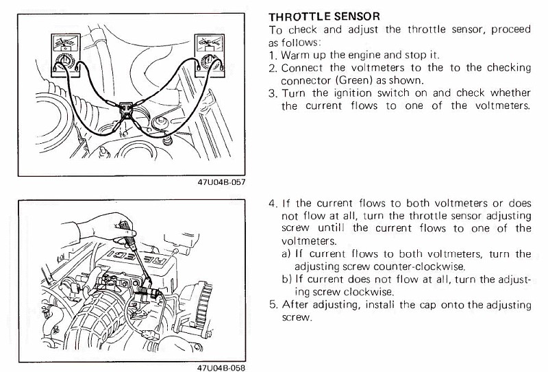
The Haynes manual and the FSM both show how to set the TPS. You can either use a pair of lights (flashlight bulbs or LEDs) or you can use the multimeter method. The lightbuld rig is the easier of the two IMO.
Trending Topics
Thread Starter
advanced novice
Joined: Aug 2006
Posts: 1,073
Likes: 1
From: clarksville tn
still cant get it to idle and still cant get the cooling system to not back flow into the overflow bottle. this car is really making me mad ive done nothing but take care of it and this is what she gives me.
when i get this thing running im going to run her hard just a little bit to make up for it and maybe ill have to put a new set of tires on it
when i get this thing running im going to run her hard just a little bit to make up for it and maybe ill have to put a new set of tires on it
Rotary Freak
Joined: Sep 2002
Posts: 2,815
Likes: 0
From: SF BayArea
This problem is perplexing and persistent.
It seems as though we've covered all the basic fuel, ignition and cooling system problems.
That seems to leave only the possibility of combustion gases leaking into the cooling system. Usually that involves an engine rebuild if it is as serious as this suggests.
Does anyone have any better ideas?
Any good ideas to detect combustion gases in the coolant?
Any ideas of how exhaust gas might get into coolant in the external systems, i.e., exhaust leaks, etc?
Senior Member
Joined: Dec 2007
Posts: 424
Likes: 1
From: Austin, TX
Use a couple of voltmeters.... Takes just a minute or so to adjust the TPS. EDIT.. it's not a TPS, it's just a TS. There is no potentiometer measuring the position, it's a simple ON/OFF switch.
That is not true. The TPS is a potentiometer. When you set the TPS position, the ON/OFF characteristic is not due to the TPS itself. The TPS adjustment connector actually leads to the output of the ECU for the vent/vac solenoids for idle control (doesn't actually connect to the TPS). In otherwords, you are not directly looking at the output of the TPS. The TPS feeds into the ECU and then you are JUST looking at the output of the ECU and putting the vent/vac solenoids in the state that they should be in during idle when you adjust the TPS. The one light on that you are trying to get means that the vac solenoid is ON and the vent solenoid is OFF.
Senior Member
Joined: Dec 2007
Posts: 424
Likes: 1
From: Austin, TX
That is not true. The TPS is a potentiometer. When you set the TPS position, the ON/OFF characteristic is not due to the TPS itself. The TPS adjustment connector actually leads to the output of the ECU for the vent/vac solenoids for idle control (doesn't actually connect to the TPS). In otherwords, you are not directly looking at the output of the TPS. The TPS feeds into the ECU and then you are JUST looking at the output of the ECU and putting the vent/vac solenoids in the state that they should be in during idle when you adjust the TPS. The one light on that you are trying to get means that the vac solenoid is ON and the vent solenoid is OFF.

Thread
Thread Starter
Forum
Replies
Last Post
trickster
2nd Generation Specific (1986-1992)
25
Jul 1, 2023 04:40 PM
ncds_fc
New Member RX-7 Technical
1
Aug 15, 2015 10:06 AM