When you click on links to various merchants on this site and make a purchase, this can result in this site earning a commission. Affiliate programs and affiliations include, but are not limited to, the eBay Partner Network.
I bought an alt for Marc's project car that's supposed to be an S5. I wired it up the way the S5 should be wired (with 12v constant on the S terminal instead of ignition-switched 12v) the same way I installed my FD alt into my car. Then I noticed something. A little while after hooking it up, before even starting the car, I put my hand on the alt to steady myself and it was warm. Also, the pulley was magnetised. Removing the 12v wire from the S terminal stopped the magnetism, not sure on the warmth.
So my question is, is this normal? And how can I tell if the alt I picked up is an S5 (and thus wired correctly) or an S4 (and should instead see ignition 12v to S)?
I seem to remember something about the colour of he band around the middle. This one's green, don't know what that means.
Installing in an FB correct?? I believe my S4 alt install had the original clip that I could use from the FB into the S4 whereas the S5 was a little different. I just used this picture
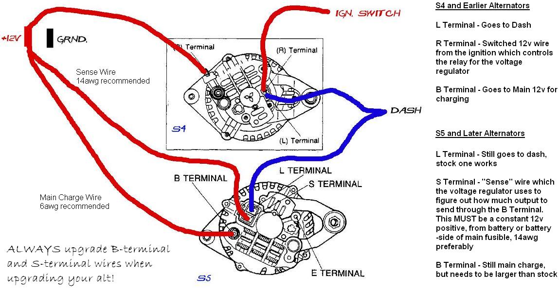
Yes, I have those diagrams and know how to wire each one. I'm trying to figure out how to tell if the alt in front of me is S4 or S5, and if it's supposed to give off heat and magnetism when it's just sitting there with the car off.
I did some digging and came up with half my answer.
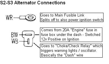
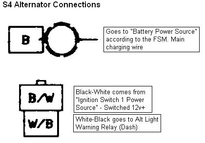
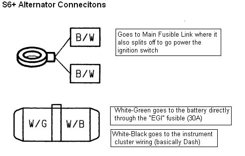
The S4 alt has a T-shaped connector of the same style as the stock 1st Gen Alts. This is convenient, as it also is wired the same way, so it would be a direct swap.
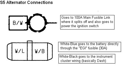
Mine does appear to be S5, which has an oval connector with two parallel spades in it. This one is indeed supposed to be wired with a constant 12v source, so I've done that part right.
So now I still need to know : Is it supposed to be warm and magnetised, or is there something wrong with this alt?
Something is wrong. The heat it's making means it's bad (not sure but maybe the diodes died). Anyway, what does it take to create heat? It takes electrical power. So this alt draws power causing a big drain on your battery. Disconnect it right now and use it as a core when you go to the auto parts store. Or fix it yourself if you swing that way.
Dammit, I thought that might be the case. This means now I have two rebuildable alt cores (I've got an FD one with a blown voltage regulator on the shelf, too).
Oh well. I'm taking it off, I'll get it tested tomorrow just to confirm, and then take one of them to the alt shop for a rebuild.
Another thing to consider when putting a S5 style alt in, is where you put the S terminal is what determines what the alternator sees for system voltage. I ran mine to the WHITE/RED Stripe wire and put a B2200 Fuse block in place of the fusible links.
Some guys just loop the 12v over to the output terminal, which works, but the alternator always sees its output voltage and doesn't load up properly when accessories are turned on. The voltage drop is much different, the accessories drop battery voltage, but the alternator doesn't see it properly.
I had an extra fuse spot, so I ran a new wire from the S terminal back to its own fuse on the fuse block, which is hooked straight to the battery. For now I've hooked the B terminal to the stock White/Red wire with ring terminal that went on the stock alt. When I did my FD Alt install on my FB I ran a whole new wire for that one, but for this project I think the stock wiring will be fine. The only thing drawing more power than the stock setup is the E-fan, so the alt shouldn't be working hard enough to overpower the white/red wire.
We took the alt to get tested. Apparently, it passed all tests with flying colours, which is strange. I'm going to check on Thursday what kind of voltage it's drawing when the car is off and go from there. I'll probably still end up getting a new one, but if this will work for a little bit without killing my battery overnight, I'll use it for now and we'll get a new one in a paycheque or two.
Depends on where you went to have it tested. If it was an autoparts house they pretty much just test that it outputs close to the rated amperage.
A starter/alternator specific establishment can validate if the internals are functioning properly AKA the reason you're getting excess heat if it's wired correctly.
Another thing to consider when putting a S5 style alt in, is where you put the S terminal is what determines what the alternator sees for system voltage. I ran mine to the WHITE/RED Stripe wire and put a B2200 Fuse block in place of the fusible links.
Some guys just loop the 12v over to the output terminal, which works, but the alternator always sees its output voltage and doesn't load up properly when accessories are turned on. The voltage drop is much different, the accessories drop battery voltage, but the alternator doesn't see it properly.
In practice it shouldn't make any difference. In fact I'd say if theres any voltage drop between the alternator output and battery it means you need to upgrade the wiring and fusible links as you did.
In practice it shouldn't make any difference. In fact I'd say if theres any voltage drop between the alternator output and battery it means you need to upgrade the wiring and fusible links as you did.
In THEORY it shouldn't make a difference, but in practice there will always be a voltage drop, however minor, across the wiring harness. The issue just becomes how much of a drop is acceptable.
In THEORY it shouldn't make a difference, but in practice there will always be a voltage drop, however minor, across the wiring harness. The issue just becomes how much of a drop is acceptable.
I'm not talking theory here. In PRACTICE it doesn't make any difference whether you loop the S terminal to the B terminal or the battery if the output cable is of sufficient size.
I'm not talking theory here. In PRACTICE it doesn't make any difference whether you loop the S terminal to the B terminal or the battery if the output cable is of sufficient size.
My in-practice experience with American cars suggests that looping the sense terminal to the battery terminal leads to an undercharging situation. It "works" but system voltage tends to be low, around 13.5v. This is even with a nice fat 8- or 6-gauge wire from the alternator to the battery. (I've done quite a few internal-reg conversions to external-reg GMs, and fixed cars that were converted by the loop method. It only takes a few feet of wire to do it Right.)
I know what you're saying about sufficient size, but sufficent size for a constant 80-120a load is shockingly large. Few people put cabling that thick on alternators.
As far as the S5 alternator is concerned, I just did this yesterday on my '84. I had no choice, as I had a failing S4 alternator, a dead S4 alternator, and two good S5 units.
What I did was look at the wiring diagram for my '84 and the diagram for an '89, noticed that both were wired the same way through the choke and check relay, cut off the connector on my wiring harness, installed two female spade terminals, and plugged it in. I think the black/white went to S(ense) and the white/black went to L(ight). I also had to put a different ring terminal on the B+ wire due to the 8mm stud on the S5 alternator vs. the 5 or 6mm stud on the earlier units. Charges just fine, 14.4v at all times, even with the headlights and 60a worth of fans running.
Well, it doesn't charge at 1000rpm, but that's due to the tiny crank pulley I have. Solution: set idle to 1600rpm.
If you wired the Black/White to S, then S won't see 12v when the car is off (it's ignition positive) so it'll slowly drain your battery when the car is off.
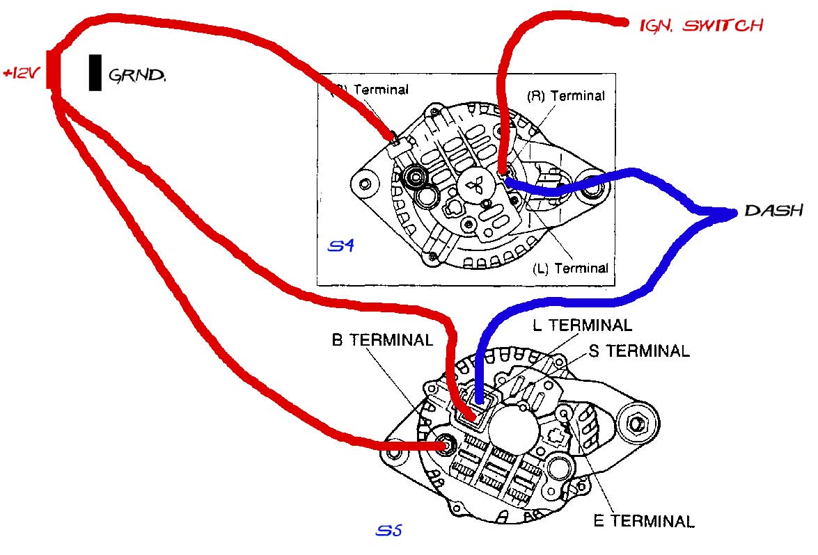
I went digging through my hard drive and found some awesome info graphics I threw together back when I did my FD alt swap. I basically went into the FSM for each year and pulled out the connector pictures, studied the diagrams and came up with this:
Honestly, I don't see what difference it should make, but all the same, I'll stick an ammeter in the B+ circuit and take a measurement. If it's under 30-40 milliamps, I won't worry about it.
Honestly, I don't see what difference it should make, but all the same, I'll stick an ammeter in the B+ circuit and take a measurement. If it's under 30-40 milliamps, I won't worry about it.
Just an addendum/followup.
I have a 168 milliamp draw on my system. I like to see no more than 30ma on anything.
Unplug the S terminal and the draw drops to 7ma. Plug it back in, 160ma.
Some checking with my Power Probe shows that the S terminal is dead - no power or ground - while the wire (as wired by the FB schematic) is getting GROUND.
So the issue is not that the S terminal is not getting battery voltage, the problem is that the S terminal is being grounded. In the FB wiring scheme, that terminal is tied into a bunch of other systems downstream of the ignition switch. When the ignition switch is off opening that circuit, this wire finds ground through the other components tied into this circuit.
Supplying power to the S terminal does not alter the draw. So supplying battery power full time to the S terminal is a quick and dirty way of preventing the draw.
I love a good follow-up post. It's always nice when you come back to a thread later to look something up and find the loose ends tied.
On my end, this car ran fine with that alt for the short time it was on the road - about a month or two before he put it in a ditch. It didn't seem to drain the battery very quickly at all so there was never much of a problem. I suspect that the alt would have lived a short life though with the heat it was generating. When we get it back on the road we'll likely swap it anyway to be sure.
Want another good followup? I just this evening got arsed enough to put a diode in the circuit
I couldn't tell you what I used, it was just a diode I scavenged. I opened up a dead airbag module to see what let the smoke out and saw a LOT of discrete components instead of surface-mount components, so I saved it for scavenging.
The diode needs to be installed so the stripe is toward the alternator. It was my first real soldering job now that I have good tools and an idea of how to do it. (I used to solder... all wrong. We'll leave it at that)
A tiny bit of ground leaks through the diode, but not enough to cause a current draw. Draw on my car is 8 milliamps with the alternator plugged in or not. Charges just fine, too. I will call this problem fixed!
To reiterate again: The problem with current draw and the S5 alternator is not that the S terminal needs to see +ve all the time, the problem is that applying ground to it will cause a draw, and the FB wiring will ground the wire with the key off. Thus the more correct solution is a diode, not a loop wire to the battery feed terminal.
I have an S5 alternator swapped onto my 85. I will take a picture when I get home so you can see how i have it wired. Mine has no problems and no phantom drains. I do not believe it is anything other than ambient temperature when it is turned off and not in operation. It has been on my car for 4 or so years with no problems. It was one of the first mods I did after getting the car and it was a great easy mod to do. However for peace of mind and knowing you have a good alternator, I would go to autozone and just buy a Reman with a lifetime warranty.
Here you go. The s5 alternator works great. No problems. The only near negative, is the voltage meter in the dash reads closer to 12.5 to 13 volts, however when measured it is running the proper ~14 volts
Yep, that's the technically wrong "loop" method instead of pulling sense voltage from closer to the battery. It won't account for any voltage drops in the system, leading to a persistent undercharge situation. You're noticing that with the voltmeter reading low.
I have never had any charging problems. *Crosses fingers. It always registers over 90% charge on battery and correct voltages when I have the battery tested every 6 months or so at Autozone so I am not sure it is undercharging. But I may try to just extend the wire to run to the battery and see if the voltmeter shows more accurately. Thanks for the tip Peejay!