
Rear Suspension links interference


Thread Starter
Junior Member
Joined: May 2005
Posts: 18
Likes: 1
From: Victoria, AUSTRALIA
Rear Suspension links interference
G'day,
I'm a new member and just had a quick question regarding the rear suspension arms, which I have not been able to find an answer for.
I have a copy of the Mazda (Toyo Kogyo Co Ltd) "Mazda RX7 Competition Preparation And Service Manual 1980" and was looking at modifying the rear arms (and diff mounting) accordingly:
Upper arm - 413mm Long
Lower arm - 495mm long
However they suggest only to use spherical joints on the bottom and rubber on the top to "prevent interference when cornering" - Why would it interfer? Has anyone tried this approach before? I was thinking of just putting spherical joints top and bottom and then see what happened.
I cannot use a three link and panhard rod as the original suspension mounting points on the body must be maintained.
A little about the car getting built:
1979 Mazda RX7
13b Bridgeport
51 IDA weber with extended fuel bowl
Toyota Supra Gearbox
5.7 Ratio LSD Toyota Hilux diff
4 wheel vented disks with volvo 4spot calipiers
Integral Roll Cage
15" wheel with rally tyres.
Terratrip computer (distance reader)
Fibreglass racing seats
Harnesses
Full interior stip including sound deadening
etc.
The car is only partly build but I was help on my way by taking all the good bits off my dad's RX2 rally car before he sold it!!
Cheers,
SR
Lives on the Forum
Joined: Jun 2004
Posts: 11,359
Likes: 14
From: Grand Rapids Michigan
I'm only guessing here, but you might run into binding issues. That's all that comes to mind with the "interference" reference....
I've never heard of that book that you mentioned, sounds pretty cool. Also sounds like a nice car your setting up. Good luck with it!
I've never heard of that book that you mentioned, sounds pretty cool. Also sounds like a nice car your setting up. Good luck with it!
Yeah, there will be binding in roll and essentially the rear roll rate will go to infinity. This is bad.
Keep the rubber bushings (soft is actually good here) in the uppers and if you feel the need to go with spherical ball joints in the lowers that will probably work.
I think the word interferance really must be refering to binding.
Keep the rubber bushings (soft is actually good here) in the uppers and if you feel the need to go with spherical ball joints in the lowers that will probably work.
I think the word interferance really must be refering to binding.
Airflow is my life
Joined: Aug 2002
Posts: 6,736
Likes: 2
From: Orlando, Fl
Interesting. I agree with the theory but wouldnt spherical joints have more compliance than rubber bushings? Eatdust, any chance of you scanning/ copying that book and sharing it with us?
Thread Starter
Junior Member
Joined: May 2005
Posts: 18
Likes: 1
From: Victoria, AUSTRALIA
Originally Posted by Rx7carl
Interesting. I agree with the theory but wouldnt spherical joints have more compliance than rubber bushings? Eatdust, any chance of you scanning/ copying that book and sharing it with us?
That is exactly what I thought!! You would think that the spherical joints would have more compliance therefore less interference issues, and with the watts link controlling the side movement I could'nt see any problem.
Has anyone else tried spherical joints? (with or without longer arms)
Have they had any trouble?
I will see what I can do about the book - I just need access to a scanner...
Or you can buy it - its attached to the back of "Mazda Rotary Performance Handbook" by John Wright - I got mine at www.pitstop.net.au.
Cheers,
SR
I think the problem with a spherical joint is that the pivot point is fixed. With rubber bushings the pivot point can move around quite a bit. The relationship end to end is not as constrained.
I think if you figured out the geometry you would find that the suspensions binds pretty easily if you can't have some movement of the pivot points.
I think if you figured out the geometry you would find that the suspensions binds pretty easily if you can't have some movement of the pivot points.

Trending Topics
Senior Member
Joined: Nov 2004
Posts: 298
Likes: 0
From: Pacific Northwest
Since the upper and lower rear links are not acting in the same plane, if you go with spherical bearings the rear might not move at all! Keep in mind that rubber bushings allow the actual pivot point to move to some degree, so that gives you some movement coupled with the spring rate of the rubber in the bushing. Spherical bearings have no (OK - very little) resistance to rotation, but nearly ZERO compliance. In a perfect static system, if you replaced all of your bushed points with spherical bearings (both ends of the upper and lower arms and all joints in the watts link) you would have a rear suspension that was solid and immovable.
My wife bought me 2 RX-7s
Joined: Aug 2001
Posts: 2,328
Likes: 3
From: Saskatoon, Saskatchewan, Canada
Originally Posted by Boswoj
Since the upper and lower rear links are not acting in the same plane, if you go with spherical bearings the rear might not move at all! Keep in mind that rubber bushings allow the actual pivot point to move to some degree, so that gives you some movement coupled with the spring rate of the rubber in the bushing. Spherical bearings have no (OK - very little) resistance to rotation, but nearly ZERO compliance. In a perfect static system, if you replaced all of your bushed points with spherical bearings (both ends of the upper and lower arms and all joints in the watts link) you would have a rear suspension that was solid and immovable.

Since the arms aren't parallel, the upper arms need to deflect in two directions, which would be limited by spherical bearings, right?
Or am I out to lunch?


Originally Posted by Boswoj
Since the upper and lower rear links are not acting in the same plane, if you go with spherical bearings the rear might not move at all! Keep in mind that rubber bushings allow the actual pivot point to move to some degree, so that gives you some movement coupled with the spring rate of the rubber in the bushing. Spherical bearings have no (OK - very little) resistance to rotation, but nearly ZERO compliance. In a perfect static system, if you replaced all of your bushed points with spherical bearings (both ends of the upper and lower arms and all joints in the watts link) you would have a rear suspension that was solid and immovable.
Exactly as I understand it to be. You can actually remove all bushings on the upper arms if you run a tri-link type setup.
Eatdust - Look deeper in the rules. Here in the states we can replace any panhards or watts devices freely. They do not consider them as "Mounting Points" This allows us to run a "v" shaped upper locating setup that will eliminate the watts linkage and then run "foam rubber" or "air" bushings in the upper arms.
-billy
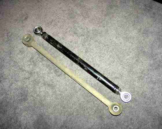
I bought lower links with spherical bearings tack welded in them. Once installed, they reduced oversteer a tad. They do make noise, clackity - clak. If you really want to fix the rear suspension, replace both upperlinks with one center tri-link, and get a real watts or panhard in there.
Originally Posted by Rx7carl
Thanks Eatdust, looks like a fathers day gift for me. 
Good point about the suspension Boswoj. I didnt consider that.
Billy, dont get the air bushing thing started on here. 
Good point about the suspension Boswoj. I didnt consider that.
Billy, dont get the air bushing thing started on here.
"Bushing material is free"
-billy
The upper links cause problems only when the car tries to lean. If the rear is moving straight up and down the upper links effectively shorten quicker than the lowers and rotate the rearend housing (top) forward. That causes problems with the drive shaft. The upper links are not parallel (looking from the top) to the bottom. The front mounts are located toward the center of the car a little. As the car leans the links foreshorten differently(they are swinging in radiuses pointing different directions) and that is what causes the binding. A spherical bearing in this location will make the problem worse. The rear will move up and down fine but try to make it lean and it will lock up. Get a tri-link and use foam in your upper links. Are you allowed traction bars? (thats how a tri-link fits the rules).
The binding that occurs leads people to use lower spring rates than ideal. They have to because of the roll stiffness they get from urethane or even stock bushings as the rear binds up.
The binding that occurs leads people to use lower spring rates than ideal. They have to because of the roll stiffness they get from urethane or even stock bushings as the rear binds up.
Thread Starter
Junior Member
Joined: May 2005
Posts: 18
Likes: 1
From: Victoria, AUSTRALIA
Thanks everyone. I worked it out last night, whilst I was lying in bed trying to sleep. The solution/explanation that I came up with was the same as mentioned by jgrewe, in that as the suspension moves it rotates the diff housing ever so slightly. This is not a problem if both sides are moving at the same rate, however when only one side moves, the suspension is trying to twist the dif housing, causing the suspension to bind.
It I believe can be improved by having nearly equal length arms but it cannot be completely removed whilst still using the 4-link design.
Does the tri-link use original mounting points? The suspension under the rules is completely free including the diff housing, however only original mounting points may be used. The body mounting points have to remain completely standard as supplied from the factory.
I could change the watts link but would have nowhere on the body to mount it. I had not gotten that far yet as I was still trying to sort out the front links.
rx7carl - I just checked, I only have edition 1 of that book, but the cover looks nearly the same, so I guess that the details will be in there!?!
Cheers
Originally Posted by Eatdust
The suspension under the rules is completely free including the diff housing, however only original mounting points may be used. The body mounting points have to remain completely standard as supplied from the factory.
Think about it this way: You need to located the axle laterally and this is what the stock watts does. If you replace it with a Tri-link setup and call it a "traction bar" you have now replaced the device that locates the axle laterally. It just so happens that the same device locates the top of the axle with the way it is designed. Now your upper links are redundant so put some soft foam rubber in them so they are still there - just not binding.
It all comes down to your rules on bushing material as well as the addition or subtraction of the watts, panhards and "traction bars".
-billy
Originally Posted by bwaits
It just so happens that the same device locates the top of the axle with the way it is designed.
If you go to a tri-link setup (www.gforceengineering.net as an example) you need to also add a panhard or modified watts link. The tri-link from Gforce really needs to be used in conjunction with the panhard that he also sells.
In SCCA IT road racing and SP autocross traction bars are allowed the tri-link fits this description. Panhard and watts links are also allowed.
Mounts need to be added to the car which is allowed within the rules applying to these two items.
Eatdust, can you post the exact wording of the rules you have to live with? Anything that pertains to rear suspension, traction bars, ADDING links etc. You may be able to leave the stock points, just not use them. You may find a rule originally written for a leaf spring car that helps you(panhard bar, traction bars). Just post as much as you can or give us a link to the rules, then we can help you get around them. 
Tri-link adds one mount to top center of diff and another one either under the tranny tunnel, or better yet inside the car on the cross member behind the seats. Running the link thru the floor. That's what I have. That way you can have a straight link as long as you need instead of one with a bend in it. Tri-links with bend have broken on the track, especially when they don't have proper gussets.
I have seen 1st gen with custome built watts link, there is room under there, but tight. I might have a pic developed of one next week.
I have seen 1st gen with custome built watts link, there is room under there, but tight. I might have a pic developed of one next week.
Thread Starter
Junior Member
Joined: May 2005
Posts: 18
Likes: 1
From: Victoria, AUSTRALIA
The applicable rules (I have not included the irrelevant ones) are as follows:
(i) The position of the rotational axis of the mounting points of the suspension to the wheel uprights, and to the shell or chassis, must remain unchanged.
(ii) Suspension components and axles are free provided they are entirely interchangeable with the original units. For vehicles with a live rear axle, the entire rear axle tube and differential housing assembly is considered suspension and is therefore free. The suspension mounting points on the body/chassis must be retained and used exclusively and unmodified and to the exclusion of all others, save that strengthening is permitted, but it must follow the original shape of the body and be in contact with it.
(iii) The top shock absorber mounting plates of MacPherson struts are free save that the mounting points on the actual bodywork must remain unchanged.
As you can see there are not many freedoms allowed in regards to adding traction rods or additional locating arms etc... Basically the body has to be keep standard and you can bolt anything to it as long as you only use the original mounting points (i.e. can’t created new mounting points).
rx7carl – I re-read my Mazda book last night, and don’t get you hopes too high in what it will reveal, it kind of reads like a part’s list, however you can still take the idea’s from it and use it to make your own parts to some extent.
Thread Starter
Junior Member
Joined: May 2005
Posts: 18
Likes: 1
From: Victoria, AUSTRALIA
I just had another question - does the standard watts link cause any binding problems or is the only problem the roll centre height - especially when lowered??
Can I put spherical bearings in it without any problems??
The reason I want it so free moving is that in rallying you need lots of suspension travel ie - 6 inches especially from side to side when cornering, so that the car really digs in.
I have been rallying for about 7 years (I'm only 26) in a KE30 & KE35 toyota corolla and this is how it works (lots of suspension travel). But I have seen the light and want the horse power and sound that only a bridgeport mazda can offer!
If anyone is interested there is a press release from our last round on www.vicrally.com.au it's the 4th article down by the "raymond crew". You can also see photos of our cars in the photo section. Just do a search under Drivers - raymond. You can aso search under mazda to see some old skool mazdas in action.
I have added a couple of photos from the last rally - i'm in the subaru legacy, and my younger brother is in the toyota corolla. If anyone wants to see videos I can upload them to a webpage for downloading.
Looks like section 2 shoots your chances for a trilink and/or panhard bar. Just thinking outloud, could you make something to attach to the car(upper link mount) and relocate the pivot point then use a stock arm to attach to a modified rearend housing. That way you might be able to use spherical bearings in the top links so the offset built into them wouldn't matter, or just make links with rod ends that would fit the stock location. Then just keep the stock watts link, its not that bad, the roll center is just a little high.
The position of the rotational axis of the mounting points of the suspension to the wheel uprights, and to the shell or chassis, must remain unchanged.
The suspension mounting points on the body/chassis must be retained and used exclusively and unmodified and to the exclusion of all others, save that strengthening is permitted, but it must follow the original shape of the body and be in contact with it.
The suspension mounting points on the body/chassis must be retained and used exclusively and unmodified and to the exclusion of all others, save that strengthening is permitted, but it must follow the original shape of the body and be in contact with it.
The stock watts link does create bind, it is not centrally located behind the pumpkin and the arms are not equal length. Plus pivot point is above axe centerline, creating a high roll center. None of that is good.
Looks like you can use spherical bearings and heim joints to heart's content. And you could upgrade the entire rear axel as long as replacement has pickup points welded to exactly the same spots. But the 1st gen rear is light, I just hope it can handle rallying. You will need to gusset the axel to take the abuse.
Looks like a budget class, which is good. Can you look at what the competetion is doing on 1st gens?
The stock watts link is actually better designed than it looks. With the unequal length arms they solved the problem of nonlinear movement by having the pivot point on the center link off center. The rear moves fairly straight through a good sized range of travel. The roll center is a little high and off center though. Like DriveFast7 said sperical bearings and heim joints will help a bit.