When you click on links to various merchants on this site and make a purchase, this can result in this site earning a commission. Affiliate programs and affiliations include, but are not limited to, the eBay Partner Network.
Welp, I put some time in Solidworks and designed some stuff today. Some of the dimensions may change and I don't have a brake mounting surface on it yet and no I haven't run any stress analysis. This would be for roadrace use with a modified stock axle.
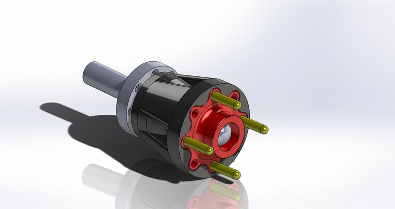
Overall view... red thing on the front is an off the shelf Wilwood wide 5 drive flange with 4 of the bolts drilled out. Trick feature one? Converting to 4x100mm so I can use Civic/Miata wheels. Trick feature two? Ability to pull the driveshafts out through the middle of the drive hub so the pumpkin can be taken out of the axle housing for all the various diff work without messing with wheel bearings - all the various diff settings or swapping ring and pinions.
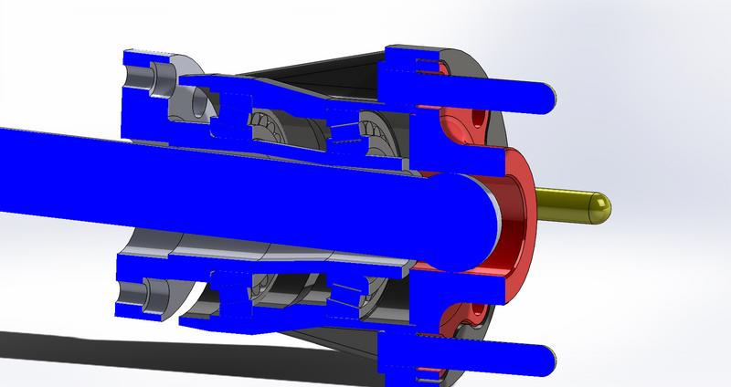
Trick feature three - camber! The ball end of the dummy axle is just there to locate things - I didn't model the splines on the drive flange (because it's a purchased item) or the axle (because it's a purchased item) But you can see that the axle isn't straight down the center of the hollow snout. In fact, the flange on the left side of the picture will end up bolting to a flange on the axle housing so camber can be adjusted without having to bend anything. The dummy axle in the middle is actually horizontal, everything else is cambered - 1.5 degrees in that version. The drive splines end up right in line with the drive axle, so there's no flexing imparted on everything from all this.
I still have some design cleanup like adding a brake mounting surface and adding fillets and chamfers and stuff but I thought it was neat.
Ha, found CAD models for the front bearing hubs. Need to take some measurements then I can bang out front hubs. Actually will be a whole lot simpler because it has to go on the stock front spindle so a lot of stuff gets sorta "defined" for you.
I really need to find a 15x7 +35 4x100 wheel off craigslist or something to throw a dead Hoosier on and test fit things - I was intending to build enough offset on the wheel mounting surface to do that without needing wheel spacers, but not sure exactly how much I need for the Hoosier EProd slick to not rub the strut.
is camber adjusted through the machining of the housing itself? I want to see what you do for the front hubs as well. I think the FC conversion works pretty good but then you are stuck with 5x114.
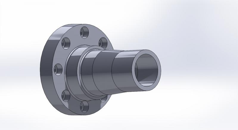
There's a picture of... what the circle track applications call a bolt on snout - the last part of the outer narrow section will be threaded, I haven't bothered to model it yet. There will be a coupler that welds on the end of the axle housing tubes in place of the existing bearing carrier that mates with that bolt pattern for the snout. You can see how at the flange the snout is off center - if it were centered it would be a version for zero degrees of camber. The reason it's done this way is because then the end with the drive splines always is in line with the axle tubes no matter what angle. Camber adjusted by unbolting the snout and bolting a different one on... harder than adjusting camber at the front, to be sure, but at least it's possible without wearing out axles.
I actually have a version of the Re Speed conversion on one of the old cars - a version using the 4-lug FC stuff and brakes. I'm not sure if it's completely legal for the race class I'm building this stuff for, though, and given the state of play of aftermarket wheels in 2018, 4x4.5 is more expensive for what I have in mind than 4x100. How's that? To get a lightweight wheel in 4x4.5 I need to go with something like a Volk TE37 or cut Jongbloed a check for custom wheels. If I modify the hubs a little bit, I can take a nice off-the-shelf Enkei RPF1 instead.
OK, that may sound like a crazy reason, but it works out to over a thousand or two bucks savings per set of wheels and much easier replacement if something gets damaged or wears out.
I definitely agree that 4x100 is the bolt pattern to go with for nice wheels. I like the bolt on snout. I like the conversion kit I did on my car too, interested in how you do the hubs could I potentially just pull the FC hubs off and put the hubs that you are working on in place with no other changes?
The front hub I'm doing is intended to bolt to the stock spindle, with the stock bearings, and will put a stock GSL-SE size rotor (albeit bolt on, 6x5.5" bolt pattern with directional vanes) at the same location the GSL-SE does to be used with a stock GSL-SE caliper. Fundamentally similar to the KC Raceware ones but with a different bolt pattern and the wheel mounting face offset outwards to eliminate need to run wheel spacers.
The front hub I'm doing is intended to bolt to the stock spindle, with the stock bearings, and will put a stock GSL-SE size rotor (albeit bolt on, 6x5.5" bolt pattern with directional vanes) at the same location the GSL-SE does to be used with a stock GSL-SE caliper. Fundamentally similar to the KC Raceware ones but with a different bolt pattern and the wheel mounting face offset outwards to eliminate need to run wheel spacers.
the idea of going from 110 to 100 is very appealing. I would love to get my hands on these (front and rear im assuming?) would love to see these make it to production
One of those things where, well, define "production". I'm making at least a few sets for myself; past that we'll see. I'm mostly worries about liability, especially if people misuse these things by putting them on street cars.
One of those things where, well, define "production". I'm making at least a few sets for myself; past that we'll see. I'm mostly worries about liability, especially if people misuse these things by putting them on street cars.
well I was hoping to use them in my street car so that I could fit 4x100 wheels
can't you simply state that buying these would be for racing purposes only, like others? have stayed at a holiday inn and in no way am I implying I know anything about the law
That is a ton of hours in Solidworks there! I have similar experience as well, in school for Mechanical Engineering now. These could be very cool if implemented properly for sure
can't you simply state that buying these would be for racing purposes only, like others? have stayed at a holiday inn and in no way am I implying I know anything about the law
I'm doing a variety of stuff where I'm going to have to talk to a lawyer and set up a business entity anyway. Absent any actual legal advice, I'm going to say that it's one thing to say that stuff like engine stuff is for racing use only... if it fails, the person is out money but not possibly dead. Insurance companies have a lot of lawyers to throw at things though, and I don't want to risk it until I've found out how to limit my liability.
I mean, I'm not saying "no I'll never sell these", just "there's legal ramifications to selling them I think a lot of people are overlooking".
Originally Posted by DreamInRotary
That is a ton of hours in Solidworks there! I have similar experience as well, in school for Mechanical Engineering now. These could be very cool if implemented properly for sure
Truthfully, like 3 hours so far but there's a lot of refinement left to do, and that's not including finding the dimensions of parts. https://cad.thomasnet.com/cadmodels.html is super helpful for off the shelf parts like bearings - that and sketch pictures for converting the Wilwood drive hubs to probably-accurate-ish 3d models.
The guys at Ronin Speedworks had to go through similar legal hoops to offer the FC Mandeville Brakes, I am sure Joel at Ronin would be helpful if you asked him, there may be a thread on it too if you search FC Mandeville Brakes
Here is a design I did to make adapters/spacers to be able to use 4X100 Miata wheels, while I was at it I added tabs to mount Wilwood rotors to the adapters. So far I haven’t used this setup yet, just conventional adapters and FC big brakes. On offset and spacer thickness, on my car with 15X9 +36 Miata wheels and 245-40-15 tires I needed a minimum of 40mm thick spacer on the front. On the back I could get by with a 20mm spacer and tuck the rear wheels in some.
Oh yeah I used the rear caliper mounting bracket as a 3/8 thick bearing retainer, I use drum brake rear housings since they are so much easier to get than disk housings and work better for me with my caliper mount design.
That's elegant looking. I have a minimum weight for the front hubs, and am trying to do at least one version where I can constrain it to be made by a guy with a lathe and mill (IE: me) if I don't like what shops quote me.
That's elegant looking. I have a minimum weight for the front hubs, and am trying to do at least one version where I can constrain it to be made by a guy with a lathe and mill (IE: me) if I don't like what shops quote me.
For front hubs I have been using stock rotor/hubs with the brake rotors machined off, and the OD turned down slightly to fit inside the FC brake rotors. Even though they are iron instead of aluminum there are surprisingly light once they are done and quite strong.
I designed some 5 bolt aluminum hubs to fit the FB spindles for some people running IT7R which is an IT first gen with a RX8 engine. They had no luck getting a shop to agree to make them, the tolerances have to be pretty tight, if you follow ISO fit tables you end up with a 7 micron tolerance on the bearing bores, and if you want the bearings to run true you end up with a true positon tolerance between the 2 bearing bores of no more than 10 microns and better at 5 microns. Since most shops would have to machine the 2 bores on different setups you can see how difficult maintaining those tolerances would be, I can share the drawings that I created if you want.
What those guys were able to get some hubs from Aerospace Research out of Florida who make a lot of drag racing parts. I was never very impressed with their parts but they did make them some pretty nice 5 bolt aluminum hubs to fit the first gen spindle, I would assume that you could get them to drill them in a 4 bolt 4X100 pattern too if you asked.
SCCA specifies the minimum weight as ... well, what the "hub" is stock, hub plus rotor plus everything to bolt the two together. Some part of me wants to reduce the amount of bolted joints if possible - I know they work but why have them if I don't need them?
I'm looking at Timken's data for the bearings I selected... for the spindles, the tolerance is pretty tight (the bearing races are probably going to be finish ground anyway) but the aluminum hubs, the tolerance isn't anything I can't do on manual machinery. Doing it in one setup will be annoying but I think I have the setup mostly figured out. I haven't done up the front hubs yet, however, and always welcome seeing other people's designs.
I don't mean to trivialize anything but off the top of my head I know half a dozen circle track suppliers that produce similar hubs, there's various options off the shelf for the 1st gen RX-7 even, so it's not impossible.
For front hubs I have been using stock rotor/hubs with the brake rotors machined off, and the OD turned down slightly to fit inside the FC brake rotors. Even though they are iron instead of aluminum there are surprisingly light once they are done and quite strong.
I designed some 5 bolt aluminum hubs to fit the FB spindles for some people running IT7R which is an IT first gen with a RX8 engine. They had no luck getting a shop to agree to make them, the tolerances have to be pretty tight, if you follow ISO fit tables you end up with a 7 micron tolerance on the bearing bores, and if you want the bearings to run true you end up with a true positon tolerance between the 2 bearing bores of no more than 10 microns and better at 5 microns. Since most shops would have to machine the 2 bores on different setups you can see how difficult maintaining those tolerances would be, I can share the drawings that I created if you want.
What those guys were able to get some hubs from Aerospace Research out of Florida who make a lot of drag racing parts. I was never very impressed with their parts but they did make them some pretty nice 5 bolt aluminum hubs to fit the first gen spindle, I would assume that you could get them to drill them in a 4 bolt 4X100 pattern too if you asked.
 01-26-18, 03:01 PM