
Need serious wiring help

Thread Starter
Full Member
Joined: Dec 2013
Posts: 174
Likes: 1
From: Yuma AZ
Need serious wiring help
My fb is a complete wiring mess from previous owner. Rats nest removed.
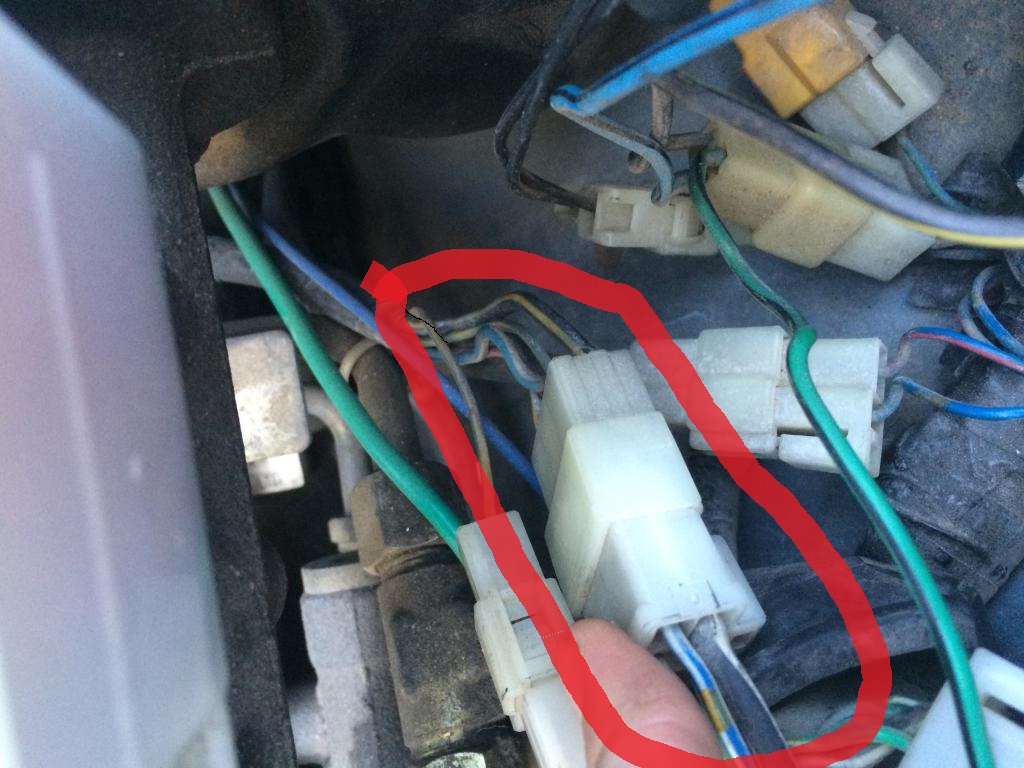
Okay well first, I have this black/white wire (which is 12v switched from the ignition switch correct?) Wiring diagram shows the blk/wht splits off to 3 different places? How does the factory wiring look for this? Shows it going to the leading and trailing coil, and then to the igniter. But how does it split into 3? And what gauge wire should be going to the coils and igniter?
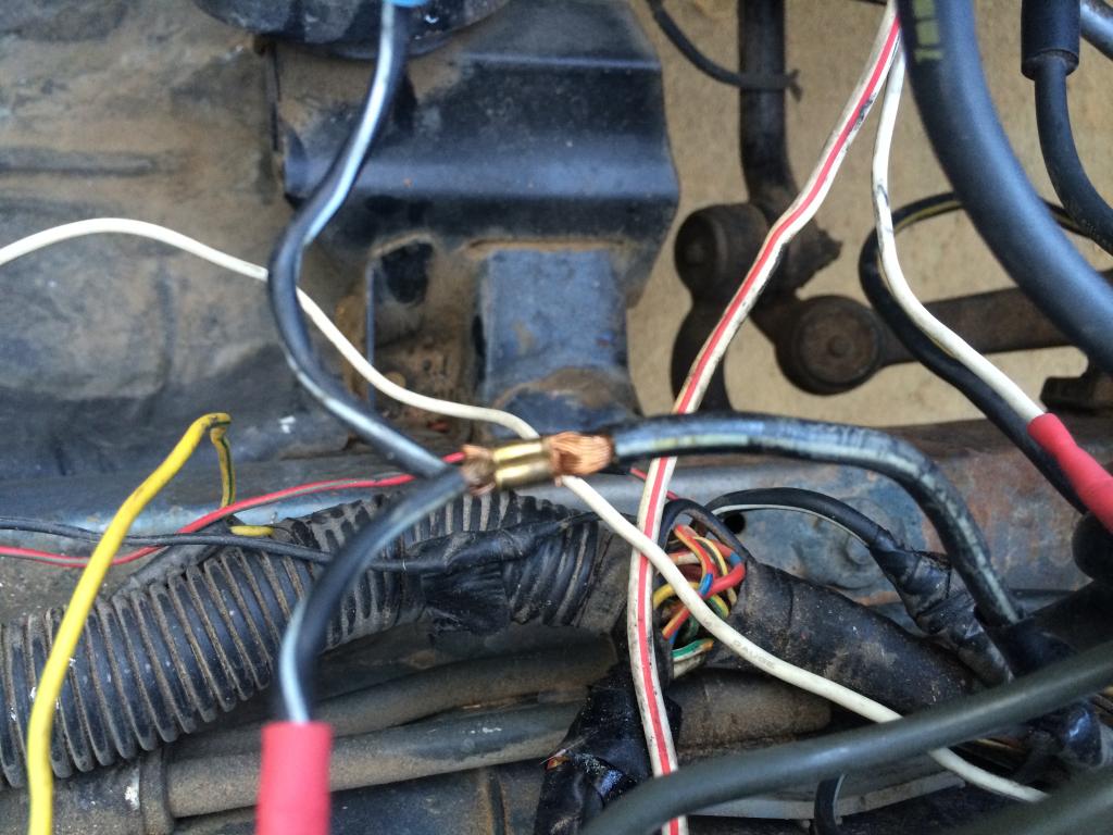
Here's a pic of it coming out of my wiring harness, which leads up to that ^^
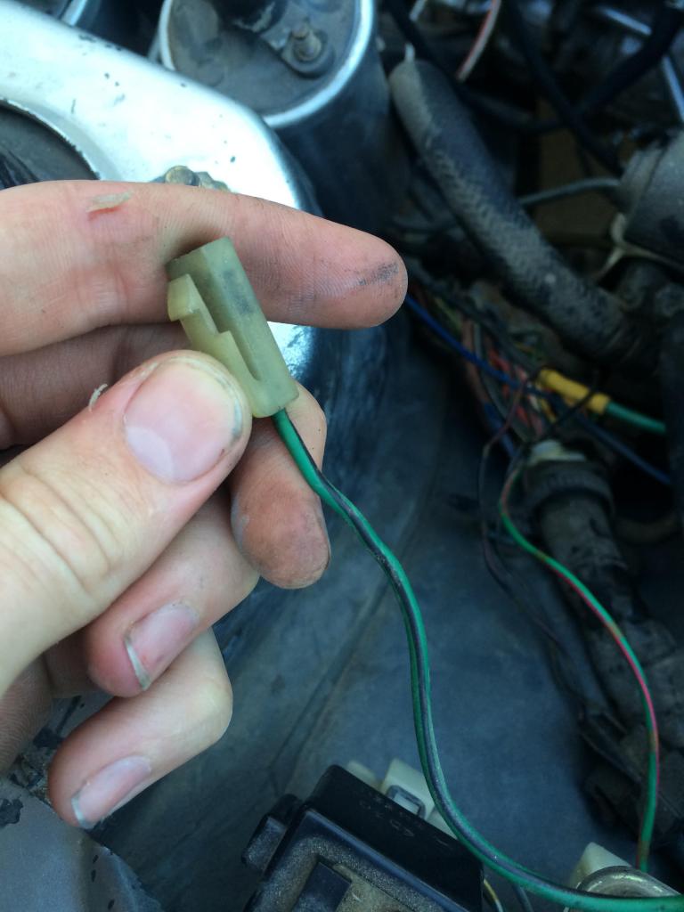
What is this wire for? Its on the drivers side close to the firewall.
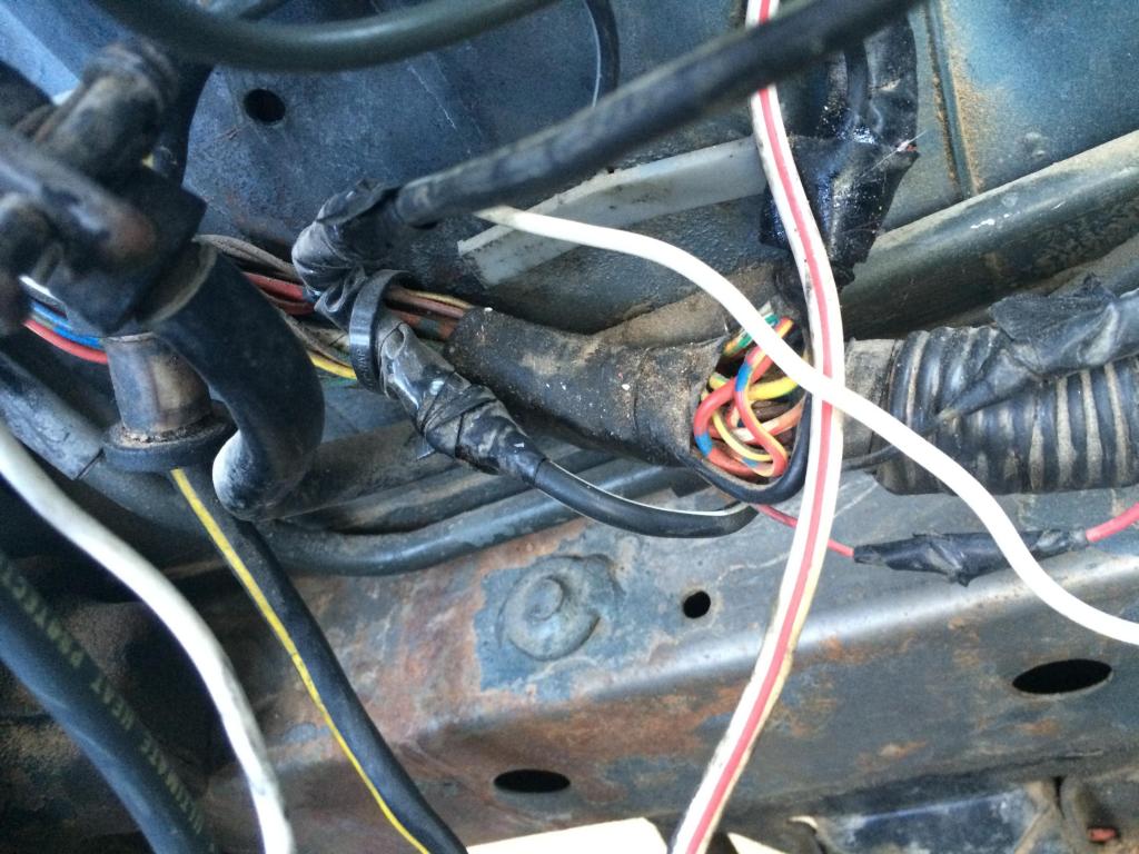
Then I have this bundle of wires coming down by my starter. What are all these for?
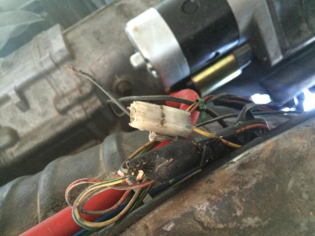
That harness ^ leads up to this connector in the drivers firewall area:
Thanks!
Okay well first, I have this black/white wire (which is 12v switched from the ignition switch correct?) Wiring diagram shows the blk/wht splits off to 3 different places? How does the factory wiring look for this? Shows it going to the leading and trailing coil, and then to the igniter. But how does it split into 3? And what gauge wire should be going to the coils and igniter?

Here's a pic of it coming out of my wiring harness, which leads up to that ^^

What is this wire for? Its on the drivers side close to the firewall.

Then I have this bundle of wires coming down by my starter. What are all these for?

That harness ^ leads up to this connector in the drivers firewall area:

Thanks!


Thread Starter
Full Member
Joined: Dec 2013
Posts: 174
Likes: 1
From: Yuma AZ
Joined: Jun 2008
Posts: 8,376
Likes: 28
From: Chino Hills, CA
The stock wiring "split points" (in-line splices) look very much like that first picture - - a crimped junction binding the 'added' wire the original without interrupting it - - but they are buried inside the harness, taped, and then the whole harness has an overwrap that protects the wires. The wiring diagrams don't show the precise location of these splices, just which connectors they fall between.
Similar splices exist on the headlight retractor control wiring, too.
The wire gauge question is a harder one, as the factory diagrams don't really mention it. Good rule of thumb is that you cannot go wrong replacing wiring with a slightly larger-gauge wire, as manufacturers will generally use the absolute minimum acceptable gauge to save costs. This is all DC power wiring and very low frequency switching; you don't have to worry about impedance mismatches due to gauge changes.
& you'll go broke if you try to buy enough different colors of wire to match the originals, so keep detailed notes on what color wire you use to replace each circuit - - you'll thank yourself later.
The coil primary wiring on my '80 looks to be about 16 gauge, or possibly one step smaller. Stranded, naturally - never use solid-core wire in a car, it doesn't tolerate the vibration well.

Joined: Mar 2001
Posts: 31,835
Likes: 3,233
From: https://www2.mazda.com/en/100th/
The wire gauge question is a harder one, as the factory diagrams don't really mention it.
Good rule of thumb is that you cannot go wrong replacing wiring with a slightly larger-gauge wire, as manufacturers will generally use the absolute minimum acceptable gauge to save costs.
Good rule of thumb is that you cannot go wrong replacing wiring with a slightly larger-gauge wire, as manufacturers will generally use the absolute minimum acceptable gauge to save costs.
i am sure in the engineering dept they had an "amps to wire gauge" chart, and i'm sure its pretty straight forward. it is probably a simple chart too, something like 0-15 amps gets xx gauge, and 15-30 amps gets y. as there aren't a lot of different wire sizes in the car.
kind of like how Mazda uses a 6mm bolt for everything up to the point where they go bigger, and then BMW just uses whatever fastener is needed, which is why you can completely disassemble the Rx7 with like 4 tools, and with the BMW you Bring More Wrenches
Joined: Jun 2008
Posts: 8,376
Likes: 28
From: Chino Hills, CA
Required wire gauge is a function of the metal used, allowable voltage drop, required current load, & the cross-sectional area and length of the wire. There's a formula for it of course, but in practical applications "cheat sheets" are used that are pre-calculated for a specific voltage, assuming copper wire.
I think I've seen three different gauges in the SA's harness not counting the battery cables, and the vast bulk of it is one particular gauge. It's fairly beefy stuff compared to what you see in later cars, too. Most of the wiring in my Z is almost scary small, in comparison.
A 16-gauge stranded copper wire, for example, will handle around 22 amps in a 12-volt chassis application, & has a resistance of around 0.004 ohms per foot.
Since most circuits (excepting primary power leads) in the first-gen are fused at or below 20 amps, 16-ga is a pretty good go-to size for repairs. But there are circuits that require larger wiring, exp. around the charging system and the main ignition switch.

Trending Topics

Thread
Thread Starter
Forum
Replies
Last Post
Adaptronic S5 Turbo PNP Unit questions
_Tones_
Adaptronic Engine Mgmt - AUS
10
May 25, 2021 05:37 AM
toplessFC3Sman
2nd Generation Specific (1986-1992)
6
Mar 20, 2018 01:54 PM
rx8volks
Canadian Forum
0
Sep 1, 2015 10:46 PM