
keyless entry wiring (micro dlr4)

keyless entry wiring (micro dlr4)
hey guys...
i'm trying to wire up a keyless entry i bought from ebay...micro dlr4 and it came with the lock actuators...
here's the question...the wiring is confusing...can someone explain to me how the actuators connect? here's a link to the wiring on the unit itself...
http://www.microalarm.com/pdf/dlr4_inst.pdf
coming out of the actuators are 1 blue wire and 1 red wire...where do they go???
callin' tokyo
Joined: Dec 2002
Posts: 1,353
Likes: 0
From: Windsor, Ontario
A closer look at the manual shows that you are running the setup in the very first picture. Your unit has onboard relays and does not require additional relays.
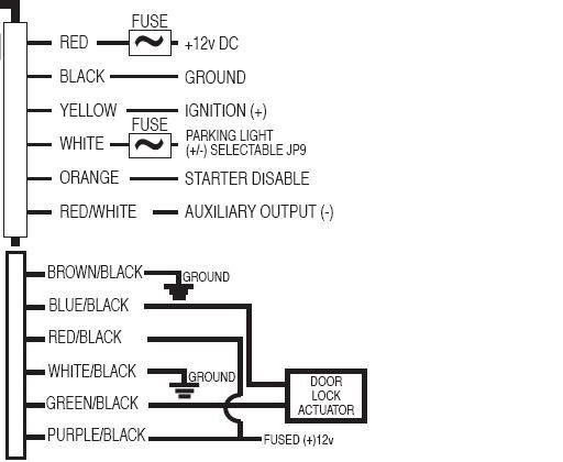
The actuator connects to the purple with black stripe and blue with black stripe wire. If the actuator's blue and red wires are backwards the lock will work backwards. Swap the blue and red wires and the lock will operate properly.
The actuator connects to the purple with black stripe and blue with black stripe wire. If the actuator's blue and red wires are backwards the lock will work backwards. Swap the blue and red wires and the lock will operate properly.
Nigga stole my bike!
Joined: Oct 2002
Posts: 1,154
Likes: 0
From: Des Allemands, Louisiana
I'm definately interested in how this product works for you. I would like to add power locks/alarm to my car, and I was kind of weary about buying one off of eBay.
How much did it cost you? Quality?
How much did it cost you? Quality?
Originally Posted by Dom
A closer look at the manual shows that you are running the setup in the very first picture. Your unit has onboard relays and does not require additional relays.
The actuator connects to the purple with black stripe and blue with black stripe wire. If the actuator's blue and red wires are backwards the lock will work backwards. Swap the blue and red wires and the lock will operate properly.
The actuator connects to the purple with black stripe and blue with black stripe wire. If the actuator's blue and red wires are backwards the lock will work backwards. Swap the blue and red wires and the lock will operate properly.
Trending Topics
callin' tokyo
Joined: Dec 2002
Posts: 1,353
Likes: 0
From: Windsor, Ontario
Originally Posted by bizarro
I tried this and although i see the LED working properly the actuators still do not respond to anything. I tested the actuators and I confirmed that they are working...I tried different combinations and still nothing activates the actuators
Brown with black stripe goes to ground
white with black stripe goes to ground
red with black stripe goes 12 volts
purple with black stripe goes to 12 volts
blue with black stripe goes to actuator
green with black stripe goes to actuator
Last edited by Dom; Nov 13, 2007 at 08:52 PM.
Is there 2 remotes with your kit? Its possible you were just using the remote that is not yet programmed when you were testing the thing out. I made the same mistake
But the wiring diagram is right, Blue/black and Green/black goto the actuators.
But the wiring diagram is right, Blue/black and Green/black goto the actuators.
Originally Posted by Dom
Sorry about that, I've enlarged and looked at the diagram again.

Brown with black stripe goes to ground
white with black stripe goes to ground
red with black stripe goes 12 volts
purple with black stripe goes to 12 volts
blue with black stripe goes to actuator
green with black stripe goes to actuator
Brown with black stripe goes to ground
white with black stripe goes to ground
red with black stripe goes 12 volts
purple with black stripe goes to 12 volts
blue with black stripe goes to actuator
green with black stripe goes to actuator
Originally Posted by Dan_s_young
Is there 2 remotes with your kit? Its possible you were just using the remote that is not yet programmed when you were testing the thing out. I made the same mistake
But the wiring diagram is right, Blue/black and Green/black goto the actuators.
But the wiring diagram is right, Blue/black and Green/black goto the actuators.
I did check out your post but I can't make out your wiring...plus my brain is bright yellow, no alarm but it does have ignition kill/starter kill...
Did you wire it like the diagram above? With the 2 grounds and 1 12v? I currently have the 12v coming on the other harness where it wires into the ignition/lights and starter...would I connect both?
callin' tokyo
Joined: Dec 2002
Posts: 1,353
Likes: 0
From: Windsor, Ontario
There is a 12 V for the brains, and another 2 for the relays inside the brain.
There is also a ground for the brain, and another 2 grounds for the relays inside the brain.
If you hear the relays clicking then you have the brain powered properly, and the remote is working properly.
You then have 2 more 12 Volts to connect and 2 more grounds to connect, and the 2 actuator wires to connect.
Ill have to take a few pictures of mine a little bit later, my brain unit is also yellow (I didn't post any pictures of mine in the other thread). I do recall wiring it exactly that that diagram though.
callin' tokyo
Joined: Dec 2002
Posts: 1,353
Likes: 0
From: Windsor, Ontario
Originally Posted by Dan_s_young
Ill have to take a few pictures of mine a little bit later, my brain unit is also yellow (I didn't post any pictures of mine in the other thread). I do recall wiring it exactly that that diagram though.
Last edited by Dom; Nov 13, 2007 at 08:48 PM.
okay...i have it working properly...here is what i was getting confused with...

the diagram above is showing the proper wiring for the brain...but then the bottom section for the locks is incorrect...what it should be is what is shown below...

so...the following cut and paste is how i have it now and working properly...
so far i've only mounted the driver side door, so I still have to wire up the passenger side...I'll be placing the brain just below my stereo...the 12v is coming from 2 wires I connected directly from the + battery and the grounds are coming from the engine bay driver side wall...I haven't hooked up the lights, ignition and starter wiring (yet...) I would like to do it sometime but I didn't want to fuss with it yet...I'll need to find the right wiring...
thanks for your help Dom and Dan_s_young ...
the diagram above is showing the proper wiring for the brain...but then the bottom section for the locks is incorrect...what it should be is what is shown below...
so...the following cut and paste is how i have it now and working properly...
so far i've only mounted the driver side door, so I still have to wire up the passenger side...I'll be placing the brain just below my stereo...the 12v is coming from 2 wires I connected directly from the + battery and the grounds are coming from the engine bay driver side wall...I haven't hooked up the lights, ignition and starter wiring (yet...) I would like to do it sometime but I didn't want to fuss with it yet...I'll need to find the right wiring...
thanks for your help Dom and Dan_s_young ...
Good to see you got it working! Its not too tough it just takes a little playing around to get it to work. I remember having to do the same thing. Enjoy your new power door locks, I think it was one of the smartest things i've done to my car! (especially because my door locks are shaved...)
callin' tokyo
Joined: Dec 2002
Posts: 1,353
Likes: 0
From: Windsor, Ontario
Cool.
The new keyless stuff comes with the relays built in. When I done my last keyless I had to wire in my own relays, into an 'H' bridge.
That unit also has the engine disable, and hatch release.
Can we have pics of the actuators installed?
How much does something like that cost?
Does it have an antennae that sticks to the windshield?
mine has an aux for hatch release as well as the ignition and starter disable...when i do the passenger side actuator i'll take pics...it required me to drill new holes into the door to mount them...
i got it from ebay...
http://cgi.ebay.com/ebaymotors/2-DOO...16652016QQrdZ1
the actuators are yellow on mine though...everything else is the same...
as for the antennae, i streched it out under my stereo down the console under the plastic...i tested it from about 50' away and it was still working...so i'm happy with the distance...
i'm yet to connect all the other stuff (lights, ignition, starter etc...) and i installed it with the wiring half ***...but i figure i'll get to all that later
Identical to the kit I used. The setup uses autoloc actuators with a lifetime warrenty, and overall everything seems to work awesome, so I think its money well spent! (especially when its so cheap)

Thread
Thread Starter
Forum
Replies
Last Post
Jeff20B
1st Generation Specific (1979-1985)
73
Sep 16, 2018 07:16 PM
edmcguirk
NE RX-7 Forum
3
May 30, 2018 06:50 PM