When you click on links to various merchants on this site and make a purchase, this can result in this site earning a commission. Affiliate programs and affiliations include, but are not limited to, the eBay Partner Network.
You should try the phenolic inserts first. Then install the boosters using the waxed finishing nail punch tool method to spread them a bit before you tap them back in place, and get them as centered as humanly possible. Then blow compressed air through the vertical holes and see how much comes through the boosters. You might be surprised to see that at least one of them is completely blocked off by the SA insert while the other just has partial flow. This will stabilize the primary circuit and is far better than leaving the stock nylon castellated inserts in there. If you experience issues, you could hammer a set of small ball bearings into the vertical holes but I don't think you will need to seeing as your venturis are still stock 20mm. Once you get to larger venturis, it can be a good idea to block them off more.
As for posts 20 and 21, I would no attempt to block the diagonal holes. That is a bit too iffy, even for me.
The the SA phenolic inserts are in there, and next chance I get, I'll check if there's any flow to the vertical holes. As for spreading the booster a little before install, well... I had read that in another thread and had actually planed on doing it, but then when I went to install the boosters, they were practically the perfect size. After I tapped them in (making sure they were as centered as I could discern), I used the bolts I bought as removal tools to check and can say with confidence that they are not going anywhere. I also purposely avoided using any grit material when cleaning the sleeve part of the boosters for the exact reason of potentially making the boosters looser.
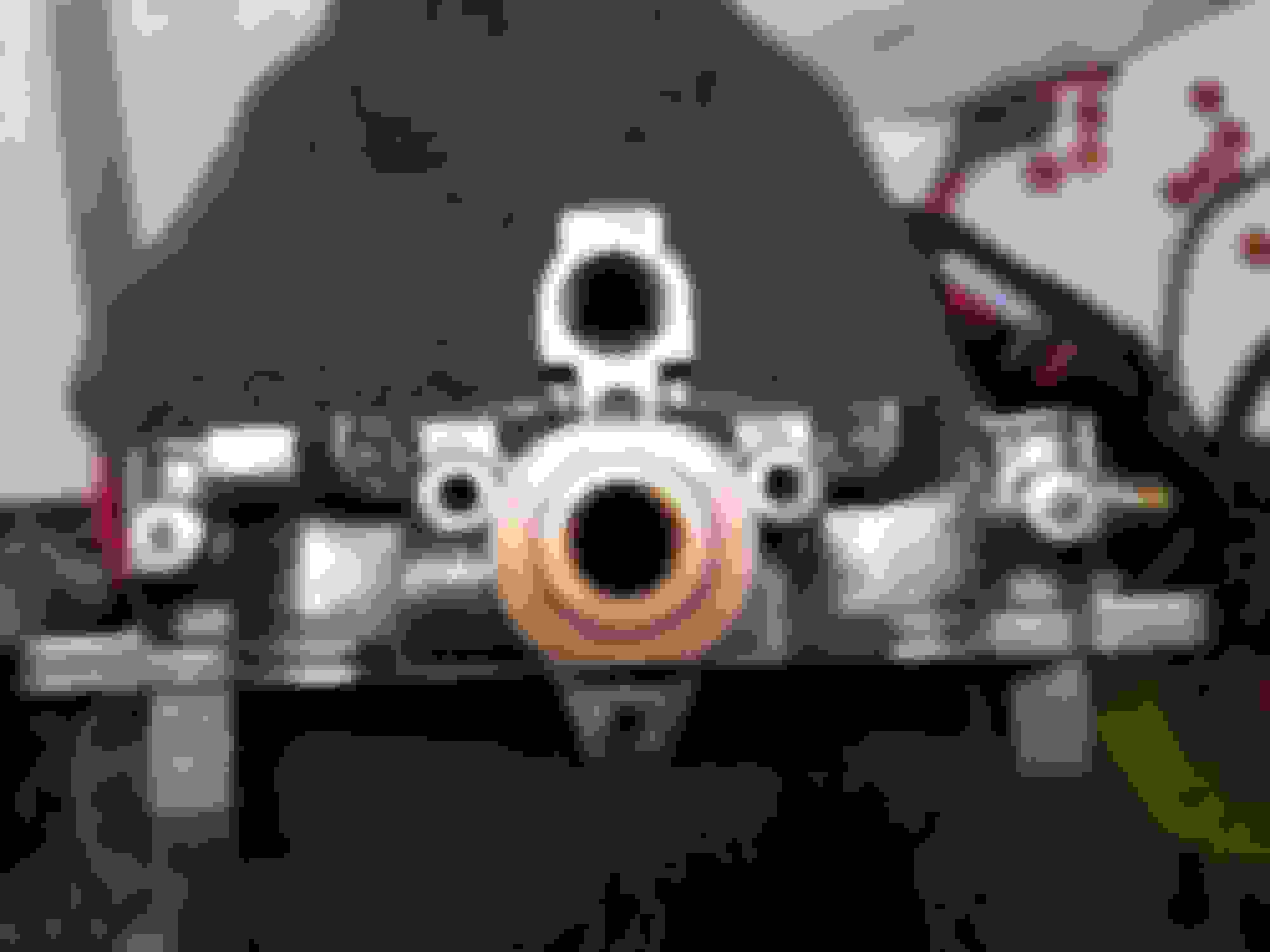
As for finding another way to block the diagonal holes, I had never planned on that - too iffy like you said. Rather I had meant blocking the airhorn side of the vertical holes. I'ma go grab some pictures of what I mean quick...
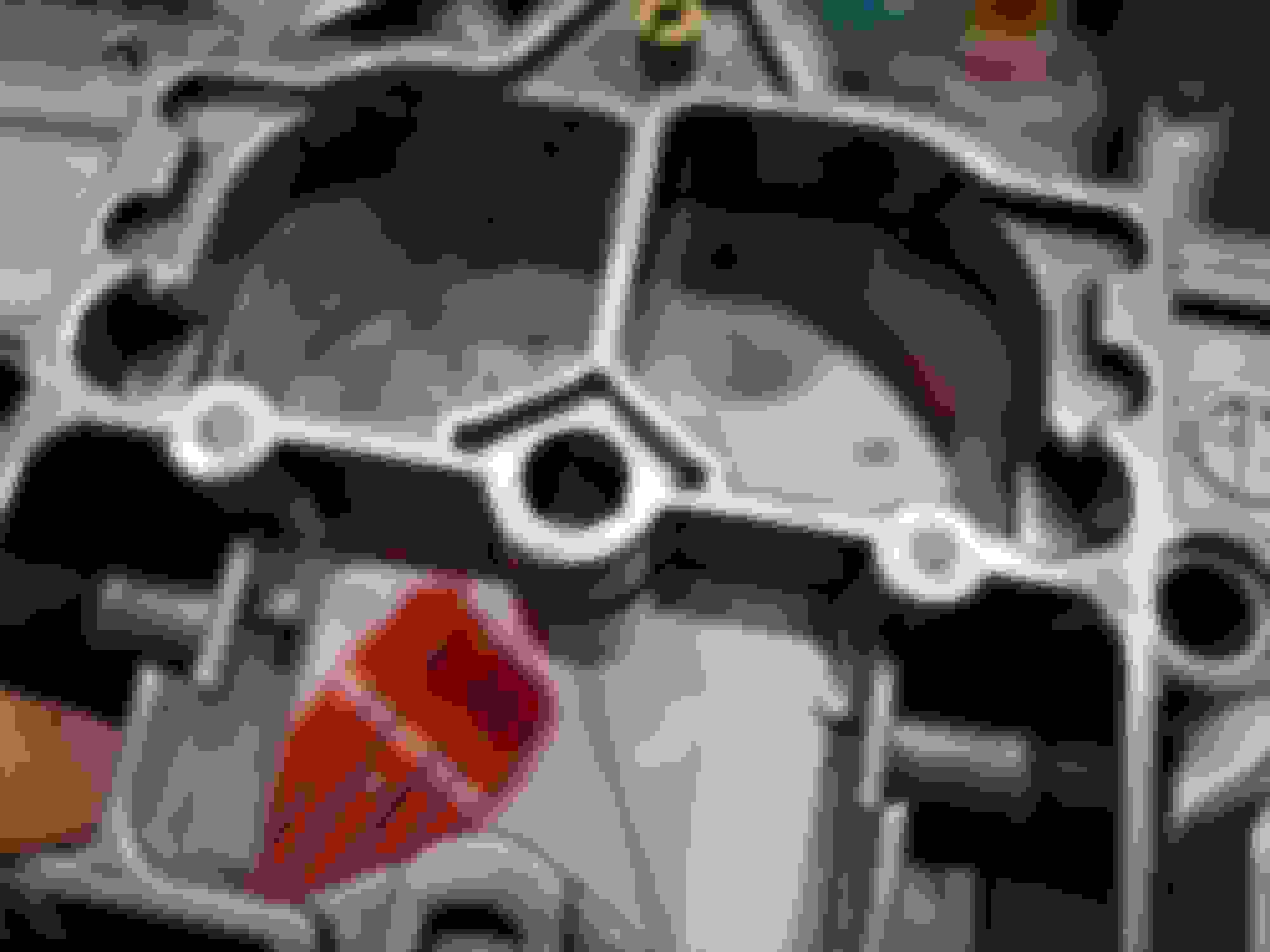
And we're back. So in the below pictures of the airhorn, the two vertical holes (circled red in the first picture) are the continuation from the vertical holes in the body. These holes then run to the where the altitude compensator mounts and join into one hole (circled blue in the second photo).
So my question is, assuming that the gasket between the two parts of the circuit is doing its job, would filling both the alt comp hole (blue) and airhorn vertical holes (red) provide a solid means of blocking off the circuit without any worry about water getting stuck somewhere (the problem with using check-***** or similar in the body's vertical holes)? I'm still using a block off plate for the altitude compensator, but if I sealed both ends of the aforementioned circuit, it would seem to be a good way to achieve a completely leak free (both for air and water) way of sealing that circuit. When I was asking you to confirm whether or not I was crazy, the above is what I had been referring to.
Also I should mention that I did some minor clean-up on the airhorn too. There are some casting marks in the primaries that I removed and there were a few other bits I tidied too. Again, probably not worth the effort, but this carb is going to be 'perfect' if it kills me... well maybe not kills me, but danged close to that .
The questions concerning a removable solution to plugging the choke flap rod holes are still up for the answering. And to go with that, what temps would you consider it reasonable to DD a car without a choke?
Oh and one more thing. This just popped in my head, but would it work to use the richer solenoid as a sort of 'electronic choke'. I know it's not at all the same thing, but perhaps it would make Oregon morning cold starts a little more dailyable? I haven't really looked into it yet, just a thought.
Last edited by Benjamin4456; Feb 20, 2019 at 06:07 PM.
Ok, that sounds reasonable about blocking the vertical holes in the air horn only which allows you to clean the main body at a future time with no worry about water getting trapped. I blocked those holes in one main body only because its top is exchangeable with other carbs I test. This made more sense for me to do at the time.
When you correct the idle air imbalance that stock carbs come with, by reducing the air bleeds from stock FB 170 or SA 150 down to 120, it allows you to easily start the engine with no choke flap. Temps range from freezing to 100 degrees F at least. You have to understand the factory intended for the car to have a choke and for the whole system to be calibrated for it, which only allows the carb to run well within a narrow temp range. By changing the size of those air bleeds, you are increasing or decreasing the range within which it will run well. In this case making them smaller increases the usable range with no negatives as far as I know... other than the choke flap becomes useless and restrictive. Well, it's always been restrictive.
I tried that idea once. It is an imperfect seal and was leading to a condition that made me realize it was leaking just enough to produce an inconstant tune at idle. I watch my wideband like a hawk. That solenoid also seemed to be incompatible with boost.
I think you are worrying too much about cold starts, but I understand where you're coming from ie this is new territory and you're open to learning things and covering your bases.
This leads me to my next thought. The 93 jets from an SA you swapped in strikes me as a good idea for now, but just understand that by reducing the idle bleeds like I'm recommending will allow less total air into the primary circuit as a whole. Thus swapping in richer jets might make it too rich and maybe what you want are a set of 91s until you hog out your venturis. What I'm talking about is all three primary circuits: idle, transition and main are intimately linked and one will not function without the other two being there. It isn't like a weber where the mains are swappable while idling. I've tried idling a Nikki without the main air bleeds or the transition bleeds in place and it was a no go.
I'm not sure how well I explained any of this. Does it make sense?
I'd say you explained it well. Just for documentation sake, here is the current jetting load-out:
Primary:
- Main air bleed: 70
- Slow air bleed no. 1 and slow jet: 70/46
- Slow air bleed no. 2: 150 (stock: 170)
- Fuel jet: 93 (stock: 92)
Secondary:
- Main air bleed: 140
- Slow air bleed no. 1 and slow jet: 160/(110 or 120?)
- Slow air bleed no. 2: 60
- Fuel jet: 160
As for that secondary slow jet, I think I may have mixed them up, which is really unfortunate because it's the only jet that I can't find a stamp on. It looks like the SA's were mostly 120's and most FB's were 110's, and I took at least one jet from an SA and the other either came from another SA or an FB. Both jets are the darker grey color (I believe some variations are also a brass tinge), but it's the lack of markings that's got me worried. Are there markings on these jets and I'm just blind, or did the stamps just get left off of these for some reason? The reason they're all switched around is due to two of my parts carbs having half of the head stripped off on only these jets from who ever rebuilt them before me, leaving me with two unpaired jets that I made the unfortunate mistake of not labeling. Is there a good way to check the size, does the finish mean anything helpful?
For going down to a 91 with the 120 bleeds, yeah, makes good sense. I'm not sure if I'll get the main air bleeds tapped before the carb is ready for testing, but when I eventually do I'll be sure to heed that advice. Speaking of tapped air bleeds, would I be wrong to assume that you drill the orifice out of the stock air bleed? Or do you just leave it alone and use the holley bleed on top of the factory one, which seems like it would compound the jets emulating an even smaller jet?
Edit: Just realized you were referring to the no. 2 air bleeds with the 91/120 bit. The question about the tapped air bleeds still stands though.
And it sounds like blocking off the richer solenoid is just a better idea for the long run.
If worst comes to worst with the secondary slow jets, I can always take the set out of my original SA carb. Then again, that still won't solve the issue of figuring out what size they are.
Quick update (yes I realize I haven't posted this yet). I just went out and very carefully checked the size of the secondary slow jets with a caliper. I have doubts that the caliper is accurate measuring the ID of something so small, but the readings were ~1.00mm (100) and ~1.10mm (110). So I suppose that just adds to the confusion, which is just dandy...
Last edited by Benjamin4456; Feb 22, 2019 at 08:08 AM.
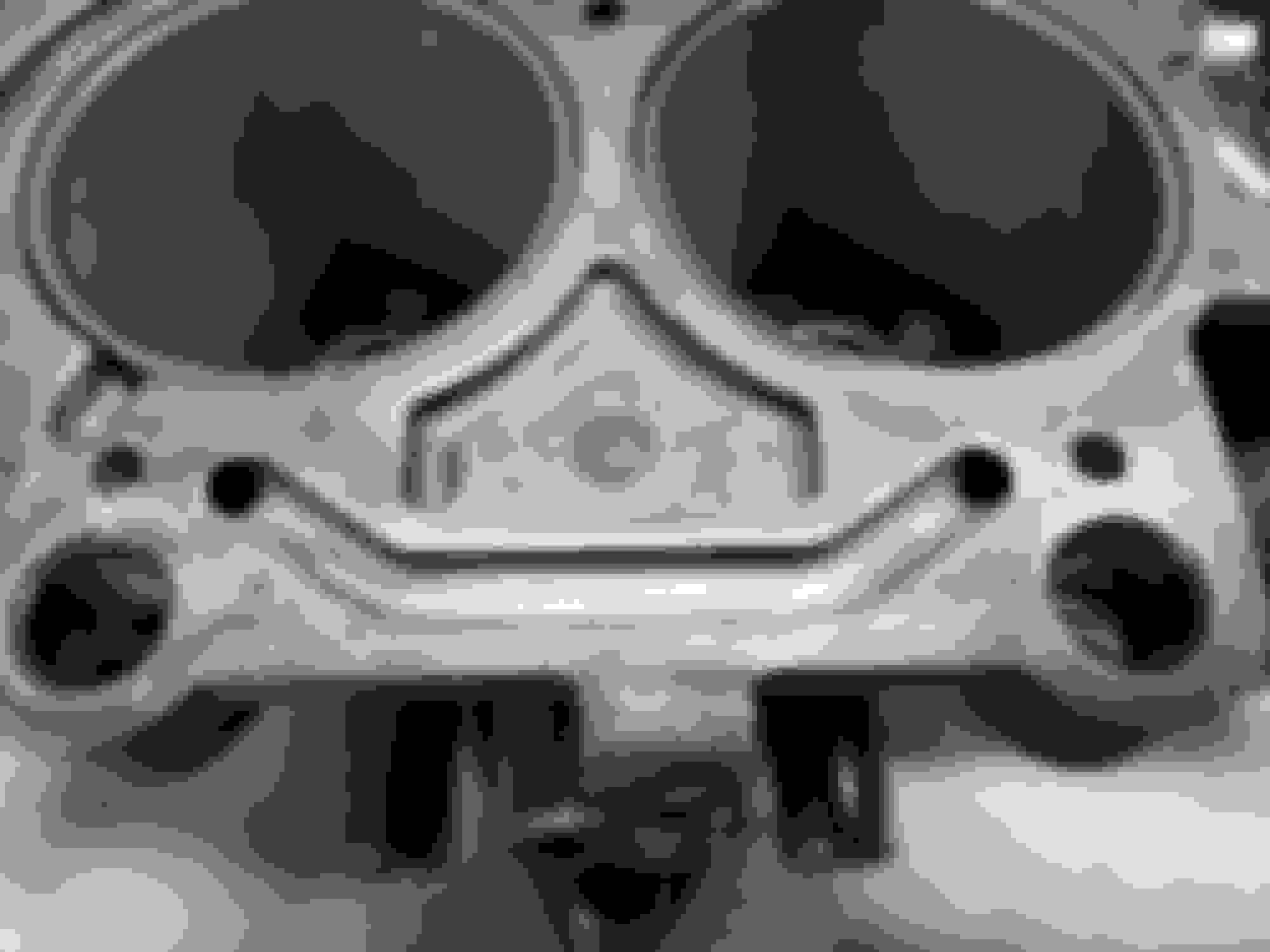
Those two holes in the divider NEED to be plugged in some way. They cause some kind of a leak in modified Nikki carbs and the carb runs lean. I have those holes in my carb.
EDIT: oops I see you are using an FB top.... never mind. I think they only cause a leak if you are using an SA top with an FB body.
Not a whole got done on the carb this past weekend as I've been pretty busy with other activities. However, here's what I did get done: filled air horn 40 jet with solder and installed, cleaned needle seats (perhaps too well...), and began cleaning linkages and other steel components.
The seats aren't exactly 'too clean', although they really didn't need to be this clean:
I got a little carried away....
And as for those steel parts (brackets, linkages, and stuff), I have decided to go all out on cleaning them, which means I am actually going to be replating them. I did some research yesterday and set up my home-brew electroplating bath. Here's the first plated piece.
Now you'll notice that it's still grey, which is due to the plating being solely zinc at the moment. I ordered some yellow chromate which will be here eventually, and that's what hardens the coating and gives it that OEM yellow tinge. It's a surprisingly easy process all things considered, and I'd say it makes sense for anyone going for an all out carb resto.
One quick question. Is there a benefit to removing the screens above the needle seats and instead running a second filter before the carb inlet? Besides easier replacement/cleaning, is there a benefit in terms of restrictions?
That's about it for now. More work will get done as the week goes on.
...
One quick question. Is there a benefit to removing the screens above the needle seats and instead running a second filter before the carb inlet? Besides easier replacement/cleaning, is there a benefit in terms of restrictions?
...
Yes it helps the flow some and is a common mod to these carbs. There is also some screens in the fuel inlet pipe connections that can be removed as well. I used to run a glass filter in my carb inlet fuel line for this reason. I've since stopped using it because it really didn't pick up anything but I change my fuel filter at least yearly.
Nice job cleaning up the carb parts. Ray will be proud of you.
I have decided to go all out on cleaning them, which means I am actually going to be replating them. I did some research yesterday and set up my home-brew electroplating bath.
Would you care to share what method and supplies you used to clean the parts and plate them? That looks great. I looked into doing this a while back for some brackets but ended up just painting the pieces after getting confused as to what to order, and how to dispose of the chemicals afterward.
Yes it helps the flow some and is a common mod to these carbs. There is also some screens in the fuel inlet pipe connections that can be removed as well. I used to run a glass filter in my carb inlet fuel line for this reason. I've since stopped using it because it really didn't pick up anything but I change my fuel filter at least yearly.
Thank you for that confirmation. I thought I had seen it before so it's good to know I ain't crazy .
As for the cleaning process, yes of course I'd be glad to share my methods. First off you need a source of relatively pure zinc - the more pure the better, although I doubt some impurities will harm much. I used some melted pennies (newer than 1982) as they are 97.5% zinc, and technically so long as you aren't profiting from the process, it's legal. Of course you could just buy a roll of zinc sheet from some outlet, but the pennies only cost me 20 cents and they were readily available. The other things you'll need are some sort of container to use as the bath (large enough for the parts you are doing), some white vinegar (5%), epsom salts, a scale, some electrical wire (~16 ga.), a sacrificial computer power supply, soldering equipment, an alligator clip, and some patience.
Once you have the above, create a mix of 1L of vinegar to 100g of epsom salts. Mix this thoroughly (some un-dissolved salt is okay). For the pennies, grab a surface that can tolerate the heat and have at the melting. I find that holding one end with needle nose pliers works well as you can heat the majority of the penny (although preferably apply heat so that the bottom relative to how you are holding it melts before the top) and then the zinc just falls out - no copper contamination. Once you have enough zinc (the more the better within reason), go ahead and combine them into two equally sized 'plates'. Mine weren't too plate-like, although as long as they are flat and have decent surface area, you'll be fine.
Get a couple wires cut that are long enough to connect between the two ends of your chosen vat. Solder one end of each of these to each plate. You should end up with each plate having one wire attached, preferably as far too a side/corner as possible as you won't want to submerge the soldered part in the solution.
Now get your power supply. If you have an adjustable bench supply, that'll work fine, but for those who don't, get that computer power supply and cut free all the yellow wires and grounds (black). Now I can't guarantee that your computer power supply will work (part of the reason it's sacrificial), but most should work fine - it really depends on how sensitive they are to 'short circuits'. The yellow wires are 12v and you'll want to connect those two the previously made zinc plates by a means of your choice (I used a spade connector). The negatives will connect to your part using the alligator clip, and I would suggest extending the length of the wires so that your PSU doesn't have to be right next to the vat.
Letting the zinc plates (anodes) sit in the solution for a little bit prior to starting will help prep it for the plating process as some zinc will dissolve into the solution. Although, when you are done plating I would suggest you remove the plates as they will eventually fully dissolve into the solution which you don't want. Next, your parts need to be really freaking clean. Have at it with the wire brush (I use Dremel attachments) and get that component clean as can be. Any rust, paint, or the like will prevent the zinc from sticking to that spot. Use a good degreaser after cleaning the parts to remove any last dirt and grime from them.
Finally you are now able to attach your part with the alligator clip and set it in the solution for plating. I suggest making some sort of jig to prevent the clip from entering the water - like a hangar - as you only want your part and the zinc plates in the solution. Also, it might be a good idea to run a junk piece of properly cleaned steel through first as it supposedly helps to pull out any impurities before you move on to your prized parts. Do runs in approximately 10 minute sessions, and between each one buff the plated portion of the part with some steel wool. As time goes on you may notice large crystals growing on the parts which is due to an excess of zinc in the solution. This isn't exactly bad, as generally they'll just fall off, but if you want to try reducing them I've seen some people add sugar to act as a crystal growth inhibitor. You'll probably want to do a few sessions (I did three per each section of the part that needed plating).
I hope that helps some. I can answer questions related to it and perhaps post some pictures of my 'janky' set up if anyone likes later today.
Last edited by Benjamin4456; Feb 26, 2019 at 06:10 PM.
Thanks! IMHO the pennies aren't that difficult, and if you're cheap like me (at least when 'cheap' doesn't cause problems), they're a great option .
I had actually been in the midst of a supplement post when I got whisked away to do something quick, so here's that:
Okay, I wrote that last post very quickly so let me clarify a couple things.
- Plating occurs best on the surfaces facing the anodes. While the plate will develop on other areas, it may not be as thick - another reason why I did so many runs, enabling me to turn the part so that most sides got a fair shake.
- This process will produce, at the very least, some hydrogen and oxygen gas. I caution those who do this to not expose flames or sparks near the bath - anyone who has messed with HHO can attest to how combustible this mixture is... For the same reason, do not seal your bath while it is running or while the plates are still installed.
- As I haven't done the chromating step yet, I can't provide any results or helpful advice. Although from what I've read, it sounds like you just dip the part in a solution of yellow chromate - for a certain amount of time - and then let that cure for a day or so (light heat will quicken this process). I got the order status in today and it looks like the 'concentrate' will arrive next Tuesday, so prepare for a chromate update sometime after that.
So there's my little spiel. As I mentioned last time, questions and concerns are welcome.
Last edited by Benjamin4456; Feb 26, 2019 at 07:42 PM.
Wheel weights are a good source of Zn. Just go to any tire shop they should have a bucket you can pick through. The Zn weights generally have Zn stamped on them; if not bring a magnet. The only other non-ferrous weight used is Pb, but that one will be easy to tell (cause lead is DENSE).
Wheel weights are a good source of Zn. Just go to any tire shop they should have a bucket you can pick through. The Zn weights generally have Zn stamped on them; if not bring a magnet. The only other non-ferrous weight used is Pb, but that one will be easy to tell (cause lead is DENSE).
That'll give you pure Zn without copper residue.
Say, that's a great idea! Nice thinking .
I would just like to put it out there that the method I detailed is not necessarily the best or only way to go about it. The aforementioned was really just some pointers and I'd encourage anyone who tries it to experiment a little (and of course report back their findings - although maybe a new thread would be better for that...?). Anyway, I hope it will give people a good starting point at the very least.
Wow, that's a hefty amount of zinc. You'd still have to make the bar into plates though - which may be interesting... Using a saw would waste a fair bit unless you collected all dust, which I guess you could melt down into a plate... intriguing... Good quantity idea though .
Here'a another small update.
The top two thirds of the carb are now assembled. Floats have been selected (I decided to give one of my FB pairs another shot), installed, and adjusted to factory spec as a baseline. I took the secondary slow jets out of my spare SA carb as I knew they were a matching pair. I've also now plugged all holes that were on the list (other than the choke rod holes which I think I'll do after I can confirm a successful cold start - just for the sake of my sanity), and I also chose to remove the vent solenoid. Here's a few pictures of everything:
Note the absence of screws in the last photo (since I'm going all out on cleaning, might as well electroplate them too.... ). The yellow chromate is still en route for Tuesday arrival.
Now I have begun working on the AP. I got some longer screws, but after making the new gaskets, I'm maxing out the throw (as in I can hear the metal cup not contacting the stops) with only one extra gasket on the reservoir side. However, the intake stroke isn't yet maxed out with again, only one gasket of the same size. I was reading through the boost prepping threads yesterday and noticed that there seems to be a 'long throw' AP diaphragm. I got the GP Sorensen kit (not the Hygrade mentioned in the threads) for both this and my previous rebuild without having read this info so.... is there a noticeable difference between diaphragms? Do note that I am using ~1mm gasket material. Related to the boost prepping threads, was the 1 & 1/8" separation between the holes on the AP arm extension from center to center, or between the nearest sides (I would assume center to center)?
Thanks for all the pointers so far.
Last edited by Benjamin4456; Mar 2, 2019 at 12:49 AM.
You probably won't be able to save the shavings to create strips of zinc because the shavings will oxidize due to their high surface area and be rendered useless for what you are trying to do.
I bring this up because the venturis are a form of zinc with other metals alloyed together to give them resistance to moisture and oxidation, but they will oxidize too. Freshly cut ones are beautiful but will dull over time.
Galvanized steel lets the zinc layer be the sacrificial lamb, so to speak, to protect the much more reactive steel underneath.
To answer your specific question about the accel pump rod extension piece, I find it is best to aim for 1 1/8 to 1 1/4 and slot the holes for easy fine-tuning. you want a long travel accel pump diaphragm, which all the aftermarket kits should come with, and you need to add a little bit of preload on it at the idle position set by your throttle stop screw. Then you need it to finish its travel as your throttle is finished with its travel to 100% or wide-open. It takes some effort to "calibrate" the mechanicals of it, but it is worth getting right. Center to center, I guess is what you are wanting to know?
Another thing that is worth getting right regarding throttle position is to change the secondary opening timing from a stock 50% primary position where the secondaries begin to open, to something closer to 75% primary opening, which whips the secondary butterflies open faster and feels tons better on the GO pedal when you are using mechanical secondaries. It makes for a far better driving experience and has a more noticeable hard spot in the pedal compared to the weak stock hard spot. This hard spot provides better driver feedback during spirited maneuvers. This mod took me a whole month to get right so don't expect miracles over night if you decide to give it a try. It is good to have spare linkages on hand too... just in case you ruin your parts. It is a more advanced mod than the accel pump stuff you are working on now, but it is along the same idea of changing leverages and lengths, working ranges and stuff like that.
Cool, thanks for that info. I started messing around with the linkages last night and I discovered something interesting. I was in the process of of stealing some butterfly mounting screws from my SA parts carb when I noticed that the secondary throttle shaft on the SA is better designed for the 'cut half of it off' mod as the full sized portion of the shaft is smaller (I'll get some pictures up later this morning since I doubt that made much sense). With that mod - I probably won't trim the other side of the shaft or the primaries much if at all (it depends on how much they flex) - and the mechanical secondaries, I'm looking at building some alternative linkages and in the process, moving the secondary throttle stop to the near side of the shaft. I'm still working out the logistics of it, but it seems fairly straightforward and I've noticed a few threads mentioning that it would be helpful in reducing the tension in the secondary shaft while closed.
The other reason that I would be building a new throttle stop would be because the SA shaft doesn't have a provision for it on the far end. As such, if I do end up building this new throttle stop, it would have the extra benefit of providing a slimmed design on the visible side of the carb. Additionally, the SA secondary shaft is held in place with a c-clip, rather than a spacer between the end linkage for the vacuum box and the t-body on the FB's. This means that if everything goes well, I could remove the remaining vacuum secondary linkages allowing me to remove the throttle shaft from either side, which I suppose might come in handy under some circumstance... probably not though...
Note that the secondary shafts between the SA and FB carbs I'm using are identical (length, fittings, etc.) other than the SA's smaller uncut portion of the shaft, and it's lack of the throttle stop.
I don't believe in thinning throttle shafts to increase CFM.
As indeed I noticed in your boost prepping thread(s), and that is also one of the reasons I'm still debating doing it. To me it seems very similar to the booster centering arms, although perhaps the placement changes that fact. I find it curious that the secondary shaft has the dual sided shaft while the primary doesn't. I would suppose this is due to the greater forces on the shaft due to the larger throttle plates and quantity of air, however the primaries must also actuate things on the other side when the secondaries do not so... I'm up in the air on this one. I've seen both opinions on the subject, and having a relatively low supply of parts (only four carbs total, and I'd like to keep at least two operational at all times), not to mention the lack of a flow bench to actually quantify the results, I'm relying solely on the opinions/data of others.
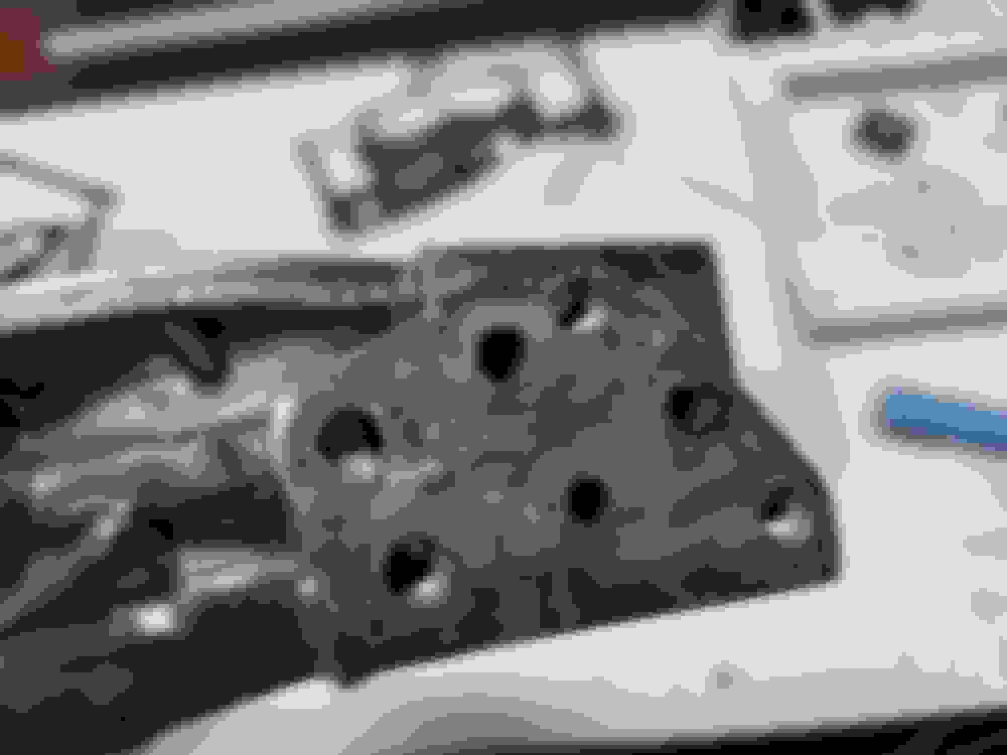
If indeed it is not that much of a difference, I would prefer to not cut them, but if something can be gained I'd be willing to cut the reinforcement side of the secondary shaft and move the throttle stop. Speaking of which, here's what I was referring to on the SA vs FB secondary shafts:
The first photo is the SA shaft and the second is the FB shaft being held above the SA one. If you look closely you can see that the FB shaft has more material that ends up in the airstream. Perhaps if cutting is not worth the torque risk, swapping to the SA shaft would still yield some (albeit small) benefit?
Who all has done the trimmed shaft mods and what were your results (data for flow changes, noticeable shaft flex or lack thereof, etc.)?
Despite fedex's terrible tracking system, the yellow chromate did indeed arrive yesterday as it was supposed to. The instructions (which are conveniently printed on the front of the package) detail mixing one gallon of distilled water with 1 - 2 ounces of yellow chromate. I did three cups to one quarter of an ounce as my container was not that large (you want something you can both fit your part in, and keep sealed because you use practically none in the process). The 4 ounces I bought will probably last forever, so long as I don't spill it or let it evaporate. For reference, I got my yellow chromate from Caswell Plating - about 37 bucks, but it should last you longer than you'll probably ever need. After mixing the solution I dipped my part for about a minute, then shook/blew it off (to save any remaining chromate solution), finally leaving it to dry over night.
Anyway, it's time for some results. I've only done the one part so far (the dashpot bracket) but...
I'd say that came out pretty freaking good for a first attempt. That last picture shows how close the color is to the original plating found on the protected portion of the bi-metal spring bracket. Right now my biggest worry is the cable bracket, as getting into all those small creases every time (first to clean, and then after each round of zinc plating), is going to be a pain. I'm also looking at re-plating the screws so that I can use the stock ones that I removed the rust from without worrying about them rusting up again in the near future. To sum it up, if you're as picky as me about things being clean/new looking when you redo something, I would certainly suggest this as a great means of rust protection and overall enhancing the look of your carb that will be under your hood where very few will see it - it's still a good feeling even if you're the only one who'll know it's there .
Now for other carb stuff. I think I'm going to try cutting the SA secondary shaft. I did some more looking and it seems like enough people have had success with it (whether or not it actually helped flow I don't know), that it's worth a shot and won't be a guaranteed waste - and if it is, I do have a spare. Also, I'm still curious about the tapped airbleeds. When you go to tap them, I feel like you would drill out the original orifices. Is that correct, and if so, by how much? I've also got my carb fuel filter now as I have decided to remove the screens like y'all mentioned.
Recently I've been doing some looking through threads about the AP, and I'm beginning to think that I might somehow have the short-throw diaphragm. From the pictures that I've seen, the diaphragm I have more closely matches the 'old' diaphragms. The only photo I've found of what I believe would be the long-throw diaphragm shows one that has a smaller outer ring (as in a larger diameter gasket section) than the one I have. On the off chance that not all aftermarket kits come with the long-throw diaphragm, will I be looking at any major issues with that - even with the AP mods? With a maxed out throw, I'm seeing about 2.5mm worth of gasket between the carb body flange and the AP housing cover.
Last edited by Benjamin4456; Mar 6, 2019 at 05:58 PM.
Thank you both regarding the plating results. It's been a bit of a mixed bag so far and I'm still refining my technique, and I actually did end up adding 100g of sugar to my solution as I was having a bit of an issue with large crystal growth, which is now reduced. I found out the hard way that you need to apply the chromate right after you've finished plating for best results (after some research too - I swear there's a forum for everything), which is why that first piece had to be dipped for a minute twenty. My second large part I did for the same amount of time - but right after I finished the plating - and it took up the color so fast I had to stop the process by rinsing it (which I never did on the dashpot bracket). Unfortunately it's become a deep yellow with little iridescence, but it is functional, so after I do some other parts I'll figure out if it's worth redoing to get a nicer finish.
Anyway, it's been a while so it's time for an update. Up until yesterday I haven't had much time to work on the carb but now I'm on crunch time (by my own choice) - the goal is to be done building over the next six days. Yesterday I removed the top portion of the secondary shaft (SA variant) and I am pleased to see that there is no notable flex. Something I hadn't notice though, is that the SA secondary shafts use the same size screws as the primaries for all years. While this may be ever so slightly better for flow, it worries me that much of the closing force is on such a small screw head - the FB's added larger screws and a throttle stop on the front of the carb. Regardless, I have successfully completed the most tedious part of the mechanical secondary conversion with no binding or potential spots for things to get hung up. I ended up cutting a new floating primary arm so that it could be longer (while also slightly adjusting the forced secondary closing angle so it wouldn't be hung up at idle), and after two revisions and a bunch of bending and other mods, I now have secondaries that fully open in only a 20 degree primary sweep (stock is closer to 40). This is darned near the maximum I think you can get without making a new, longer connecting rod for the primary to secondary arms. I also tuned the opening angles a bit as I noticed the throttle stops were allowing them to over-rotate a little. Now both the primaries and secondaries stop at straight up and down.
Today I'm going to continue plating, and also make a new secondary arm (the outermost one that attaches to the shaft). My reasoning for the new secondary arm is that I want to build a throttle stop on it, and add a second 'finger' on the other side of the freely rotating piece (the one people usually wire or weld together). I figure adding the second finger on the other side will allow easier disassembly, be sturdier than a wire tie, and avoid welding (which I don't have the equipment for). And as I already mentioned, I would be remaking it anyway to add the throttle stop so, might as well.
Concerns, suggestions, silence... all are welcome.


 .
.


 .
.