When you click on links to various merchants on this site and make a purchase, this can result in this site earning a commission. Affiliate programs and affiliations include, but are not limited to, the eBay Partner Network.
Yeah sure thing, I guess this has been going a long time hasn't it.
Running mechanical secondaries with the timing mod so they open later (about the last 20 degrees of primary travel). Stock everything on the secondary side which I believe would mean 140 main air bleeds, 60's on the no. 2 slows, and stock no. 1/slow jet so 160/110. Fuel jets are stock 160's.
Primary side is set up with 70 main air bleeds, 120 no. 2's and stock no. 1/slow jets which should be 70/46. Fuel jets are 92's.
Last edited by Benjamin4456; Apr 30, 2019 at 01:25 PM.
Ok, the secondary main air bleed is stock at 140. That is a lot of air when running mechanical secondaries,. Too much actually. We need to speed up the emulsion system and reducing the air bleed on top down to 80 is how I do it. Any smaller will not work very well (tried 70 and it was too small). The range on these I've seen is 100, 120, 140, 160 with 160 being the worst and 120 being the best because the 100 had a different emulsion tube under it. What I do is I machine the head to be a little bit shorter and to accept a pilot jet drilled to 80. Drilled, threaded, slotted etc.
The long slow bleeds I fill with solder in the upper chamber only. The lower chamber must remain open for the nickel plated 60s to flow down and through the channel down there in the bottom section of the main body. It also flows from the main emulsion "well". It basically links all three circuits together.
The nickel plated 60s can remain as they are unless you are wanting to boost it. Then you will want 35 to 37 but no larger than 40. There are ways to accomplish this but the smallest I've seen sold in this thread size are 50.
If you can reduce the mains down to 80 and solder fill the long slows, it will eliminate the delay or bog you are currently experiencing when the secondaries open. With reduced unwanted air, you could swap to smaller secondary fuel jets. I've found that 145 on stock 28mm secondary venturis is a good size. If your secondary venturis are larger, you can use larger jets but never any bigger than the stock 160.
Interesting; makes sense though. When you are modifying the main air bleeds to accept other jets, are you drilling out the original air bleed 'jet' or just leaving it as is? Seems like you'd leave it alone, but just clarifying. Also, any pilot jet in particular (I've seen some pictures where these have been tapped to accept what look like the no. 2 bleeds)?
I assume you're referring to only filling the secondary long slows (tops only), not the primaries too.
No plans for boost yet, but maybe further down the road. More power while retaining streetability is always a temptation.
Sounds like a plan. Probably won't happen too soon though - a couple weeks out at least. Though, would it be beneficial to solder fill the long slows now even I can't do the rest, or should I just wait until I can do everything at once?
Might be going with hogged venturis this summer, although I need to sort out a few other issues first (and pick up a wideband). Any additional thoughts about the persisting hard starts other than relentless carb gremlins? I'm assuming the touchy idle mixture is due to the 92's combined with the 120 air bleeds - when I get some more fuel jets I'll try some 90's or 91's to see how that affects things. I also still have more backfiring than on the previous carb if that hints at anything. The exhaust is tight and the only change since has been the carb so... general thoughts; hypotheses? Many thanks for all the help so far.
Edit: Just realized I don't think I ever fully explained the cold running issues (note that all of these vanish after it's up to temp). So cold starts (below ~45-50 F) take a few tries, but it's a carb with no choke so I get that. However, if the car isn't warm yet and I hold the throttle anywhere between idle and about 2.5k, every time, the engine will sit there for second or two and the suddenly die. There is also poor throttle response and tapping the throttle - not a major jab mind you - is more likely to kill the car than to blip the rpm's.
There's also the issue of the idle dipping after having been driving and then putting in the clutch. This has happened so far on every carb I've used on this engine/car and seems to be dependent on the idle mixture being too lean, although now I'm getting 'rich' idle misfires and this dipping-while-returning-to-idle issue still occurs, particularly if it's not fully up to temp yet. Anyone run into this before? Ideas on both this and the cold start symptoms?
Last edited by Benjamin4456; Apr 30, 2019 at 07:15 PM.
I reduce the head of the air bleed until the slot is gone. Then I cut a new slot. Then drill, then tap with a regular and then a bottoming tap. I try not to go too deep because this can ruin the air bleed by making the emulsion tube fall out.
Upper chamber of the secondaries only. If you mess with the primaries in any way, you've ruined them. Believe me, I've tried.
It is beneficial to solder fill the long slows now. You might notice a reduction in the bog or delay you are currently getting. Heck it might solve it for you all together with no additional work required. Wouldn't that be a treat? All i know is a fully modded set of sec air bleeds prevents a bog, even when you floor it at 2000. Try that on a carb with all stock secondary air bleeds and I doubt you can open them at any lower than 3800 (that was my finding back when I first tried mech secs).
Don't know what to tell you about the backfires. Hard starts could be a clue but I don't know.
Awesome, thank you for that link. Any chance you remember or could check the thread pitch on those?
The tapped main air bleeds will be next (or at least are on the list). As soon as I have more time and can get the parts here, they'll happen.
Ok, I had some time this afternoon so I filled the secondary long slows. Now, I haven't had much time on the road since, but with what time I've had I'd say there's a definite improvement. I still can't nail it under 3-4k without a bog, but even so it is much less of one than before. And wow, 2k full throttle sounds great. Definitely looking forward to when I can do the work.
As for the starting and backfiring issues, yeah, I don't know either. Next time I've got a weekend free that I don't need the car I'll take off the carb and fully inspect everything. The cold start issue is particularly curious to me though since it's happened on my other carbs too (literally almost the exact same issue, although with a choke and actually using the fast idle I rarely noticed it). You know what, I just realized that with this carb, the cold start issue has actually improved slightly from the other carbs, although since I never tried to idle without first 'fast-idling' for a few minutes on the previous carbs I never had these issues. Keep in mind above 2k the car normally will, and the same goes for the other carbs, not die even when cold. Huh, now that I'm thinking about this more... I think I need to look at some of the other systems. Maybe I'll double check fuel pressure/flow if I can find a gauge while I'm at it. Makes me wonder about the engine again too... I also still need to add the "shielding" wire to my leading ignition signal wires, so perhaps that will help with the idle misfires by reducing noise when the dizzy isn't producing as strong of a signal.
Thirteen days later and I have compression test info! I ended up building my own tester for cheaper than I could get one done (thanks to the tutorial by Twisted Rotors) and so now I can do them whenever I find a need. I did the test using the trailing plug holes (I've encountered sources stating to use both leading and trailing, so not sure if I chose correctly) shortly after I had come back from a parts run. Anyway, here's the data:
Front (average per face):
- 1: 112.26 psi
- 2: 116.61 psi
- 3: 114.00 psi
So from what I've found 110 psi is about the lowest end of the 'normal' range with anything less than 85 warranting a rebuild. Now that's just what I found, so feel free to correct me on that. That being said, it doesn't seem like my hard cold starts or misfires are coming from low compression which is good seeing that I still have a decent engine, although a little annoying considering that my issues lie elsewhere. I haven't had time to add the ignition shielding yet; still not sure when that will happen.
Now here's the deal. Ever since starting this 'project' I had planned on swapping in a 12A from my '82 parts car which ran quite well in my presence (as opposed to the current one which had not run in a long time before I broke it loose). At this point I'm quite close to being able to refresh the '82 engine, and due to some mistakes with purchasing a clutch kit, I'm getting pushed that directing even quicker. The '82 engine seems like it has been rebuilt recently (or at least at some point, though I will confirm this after it is disassembled) and it doesn't have too many miles, which is why this would just be a 'refresh' - not to mention budget constraints. Assuming all is well, I'm planning on running Pineapple Racing's large street port for the intake and exhaust and replacing whatever components warrant it. The reasons for this swap is two fold: 1, I've wanted to run a street ported engine for some time and 2, the clutch kit I purchased was for the 81-82 model years (as I have now discovered, the car currently has an 83-85 12A). I suppose a third reason is that my current engine leaves oil clouds after full throttle maneuvers that I have not been able to track the source of, as well as the excessive amounts of water vapor I get on any morning colder than 45F.
Tying this back to the original thread here, the street port will of course require more Nikki work - machined aluminum venturi's will still be happening this summer, just like the engine swap - as well as some other things. Of course I'd like to solve my issues before then and I will keep trying to hunt them down, though now I have electrical gremlins to solve too (my dash doesn't work on cool mornings and my ignition switch is in need of another rebuild or replacement). So here's what I'm thinking; I can't do any more full throttle testing as my clutch will slip (that's another story) so tuning the secondary transition might go on hold for a little while longer. Admittedly I'm still quite new to rotary engines and I've never known anyone who daily's a large street port on a carb setup (large enough for some overlap), so thoughts on dd'ing a 'large' street port? Consider that Oregon gets a bit chilly in the winter, I don't have a choke, but that as long as it will start - even if it takes a few tries - I'm willing to deal with it. I'll wrap this up here with the original content, my compression numbers. Is my analysis correct? Are they reasonable and shouldn't be causing any of the issues I'm encountering? Thanks for the help and my apologies that I've taken this a bit off topic - it'll get back on track eventually, just wait for the warm weather
Last edited by Benjamin4456; May 14, 2019 at 06:32 PM.
Good to know, thanks.
Those numbers were normalized for 250 rpm, actual cranking rpm was about 260-270.
Temperature was not compensated, though it was near 64 and and from I've found 59 is the factory baseline so that seemed close enough. My altitude is only about 200ft so I didn't think that warranted any compensation. I did, however, figure in the dead space of the 12A plus the tester so that's something to note.
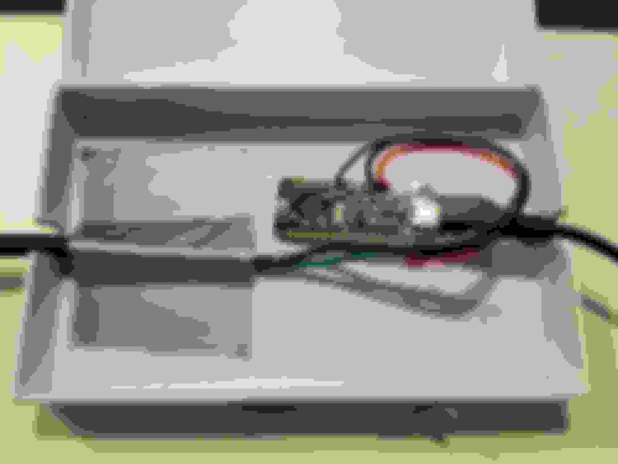
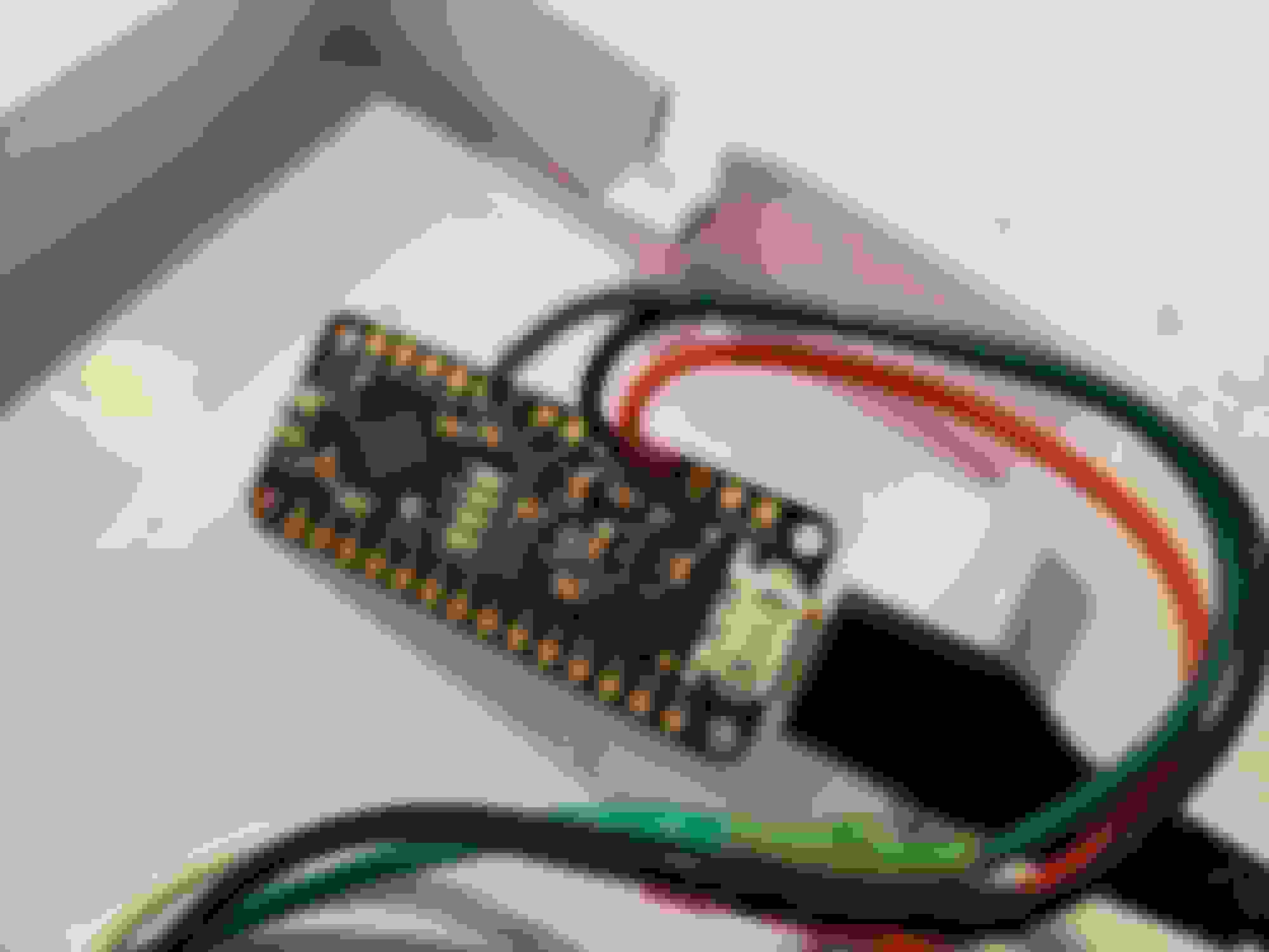
Yeah sure, here's a couple pictures from when I finished the test:
The box is just something I had lying around - I already have a better container to put everything in once I have some more time. The chip is a Metro Mini that I chose over the Arduino suggested by the tutorial as it has a built in serial to USB which meant fewer parts to purchase. Right now it connects to my phone via an OTG adapter and I have an app that can connect to it as a serial viewer (here's a screenshot of what I see when testing):
Right now it outputs in bar, but I just put the data in Excel with some equations so I can easily find all the parameters in psi as well as automatically finding averages and max deltas. Right now the code is set to work as seen in the photo (I can't take the credit for that program), although I'm modifying it to allow either bar or psi to be selected as well as altitude and additional dead space correction. Eventually I'll add an LCD to make everything even simpler and contained. The sensor is built from a non-fouler, a brass adapter, and of course the sensor of which there are many options. I picked up the o-ring at harbor freight for cheap in a large set. Total cost was a little less than 60 bucks. If anyone has any other questions about the tester I'd be glad to answer them.
Any thoughts about the porting? This is something I have no personal experience with so any pointers there would be greatly appreciated.
Ok, I've finally figured out why the car has been so difficult to start across multiple carb/intake/ignition setups - it's the fuel pump, or at least something with fuel delivery. I've had this theory for a while now but I just got the chance yesterday to check it since the engine has to be cold. Anyway, what's happening is that the fuel level in the bowls when cold is not being maintained properly. Sometimes it's as low as the bottom of the glass, and the lowest level occurs right at the point/range (rpm) where the car does the 'suddenly die' bit. I also noticed later that the fuel pump isn't keeping up when up to temp either, although it's not nearly as bad. I can hold the throttle at about 4k in the driveway and the fuel level goes down slowly.
So, what would cause the fuel delivery to change with temperature. My theory is that the fuel pump is getting stuck or something (like the reciprocating piece) when it hasn't run for a while - not sure why that would be though. Also consider that when I confirmed the cold start issue it was high 60's outside, although the problem does get worse the colder it is.
Now this is a quick post since I don't have much time right now, but I figured I'd just throw this up for theories so... start theorizing . I'll better explain this later if it didn't make much sense.
Is it a stock pump? Original to the car? I don't remember, did you mod a nikki that will need more flow than stock? If all the answers are yes you might want to look a pump that can support your mods and a good fuel regulator (not Mr Gasket type).
The pump is stock and is most likely original to the car. I have not yet made modifications that require much extra fuel, although with the upcoming milled venturis and street port I was expecting a need to update the pump anyway - I suppose this is good timing then isn't it. For a while now I've been looking at the carter pump swaps as they sound like they give a decent blend of quietness and performance, while also not breaking the bank. As for regulators, I've seen mixed opinions on the chrome Holley ones, although it seems like a fair number of people use them without issue. When running a regulator with the Nikki should the original return be used, or should it be deadheaded and then a return-style regulator used in its place?
Edit: Just noticed Summit and Jegs (probably others too) have some house brand ones that are comparable with the Holley's.
Next chance I get I'll test the power getting to the pump when cold and up to temp to see if that's part of the issue. Although when I do replace the pump, I had planned on running it on a relay regardless since a few people have noted improvements over using the aging stock wires.
Once again returning the porting, I'm really just curious how porting (in this case a large street port) affects cold starting and overall drive-ability. If anyone has some info on this feel free to chime in. This is something new to me and as of yet, research has not yielded much.
Last edited by Benjamin4456; May 20, 2019 at 07:26 PM.
I use a Carter 4070 pump (can be loud depending on how well damped it is with rubber standoffs), a Holley regulator (some have noted over the years that they are not the best), I have the regulator and a psi gauge mounted on oneside and the fuel lines coming in and out. I'm using a 0-15 psi gauge which is not the most accurate, 0-5 is better. I regulate the pressure down to about 2.5 psi and I run a return. I would recommend the return but make sure the restrictor is kept in the return line.
I suspect the Jegs and Summit brands are made by the same folks that make Holley these days.
To diagnose the pump, pull the hose to the carb and see if its A.) flowing enough volume and B) check the pressure as well. It could be the pump or the old wiring driving it. Its worth it to do a temporary direct positive wire to the battery and a good ground and retest. If the pump meets specs then you know it's the old wiring and you need to do the well known relay trick, I have that in place as well.
Awesome, good info. I had already been looking at the 4070 so it's nice to hear that it's being run successfully (not many of the threads I read mentioned a PN). Thanks for clarifying the the return set-up too.
I might get a chance to test - and potentially rewire - the pump this coming weekend. I don't have a good means of pressure testing it at the moment, although a flow test is easy. Hopefully a rewire will help lessen the issue until I can get it replaced sometime in the next month or two when the engine and carb work happens.
I'm really curious to discover why temperature (and whether or not it has been running recently) makes a difference for the fuel pump - I'll probably find out if I test it this weekend.
Turns out the pump passes the volume test (about 1.5 quarts per minute, spec is 1.16 or greater) so no issue there - wow, just realized how much more the Carter flows than stock. Anyway, as I mentioned before, I don't have a means for measuring the pressure so for the time being that will remain unknown (I'll look into borrowing a gauge). I did some more driveway testing and by 4k rpm the bowls are consistently down to the bottom of the sight glass, so there is most definitely a fuel delivery issue somewhere. You mentioned a restrictor? Are you referring to the one in the fuel inlet/return assembly, or somewhere else? What are the odds that a stock-ish setup could run decently without it (trying to narrow down the likelihood of having left it out by mistake in the carb rebuild/modding). On second thought, the restrictor wouldn't change its affect based on temperature, so I'd think that wouldn't be it. I should also mention that the filters are in fine shape (replaced recently and it's transparent so I can confirm it's free of debris). I haven't had a chance yet to check the power getting to the pump, although perhaps sunday will have time for that.
Theres a few screens in the carb. Are they all clear as well? Each needle has one and each leg of the fuel lines to the bowls has one as well (if I remember correctly). I thought stock flow was around 30gph or 1/2 gpm.
You do remember correctly, although all of the screens have been removed and to serve their function an additional, 40 micron filter has been placed just before the carb (it too is clear).
The flow figure I found was in the Haynes manual and yeah it does seems low (haven't looked in the fsm yet). 1.5 quarts/min works out to about 22 gph, so relatively close to 30. I saw another post that mentioned closer to 17 gph which is the same as the Haynes manual states for the minimum.
I still haven't had a chance to check pressure or power.
Ok, a new fuel pump and a good while later it's time to get back into nikki modding. Unfortunately my lathe access fell through - at least for the foreseeable future - so I've decided to try to make my own system for machining the venturis. That said, I'm curious about what the consensus is for the profile of the venturis these days. From what I found it looks like straight angles to the landmark hole with no 'flat area' is the best shape to aim for - there was a graphic on the forum that showed this, although I can't seem to find it now. I've got a couple extra venturis I'm going to try and cut if I can get my makeshift trimming tool properly balanced. I plan on going for 24mm primaries and maybe 29mm secondaries (although I might not mess with the secondaries yet, we'll see).
So essentially for now I'm looking for venturi profile suggestions and any tips on cutting the venturis without a lathe (although I am going to find a way to spin them while working on them, so sort of with a lathe, sort of...).
Last edited by Benjamin4456; Jul 28, 2019 at 01:47 PM.
Well if anyone has some venturi profile suggestions/comments, I'd like to cut them today so... no real rush, but I'd appreciate at least knowing if I'm headed in the right direction here. Anyway, the jig I ended up with is a bench grinder (hold on, hear me out now) with three pieces of scrap wood (sort of trim board like, not plywood) screwed to one end with a hole in the middle. Sketchy? Sure... I used a mower blade balancer to balance each piece of the assembly (it's in three parts/planks) so that vibrations are kept to a minimum and I've got to say, while it ain't perfect, it's going to get the job done just fine; I think. To hold the venturi I simply drilled a hole and then expanded it with some sand paper wrapped around a dowel while the assembly was spinning so that it became perfectly centered. I actually went a little large the first time on accident so I've got some sandable wood filler setting up before I go at it again - hopefully it will fit properly this time. Of course I'll have to remake two of the three pieces in order to do the secondaries, but that's a minor technicality. If this DIY method is something that people might be more interested in I could do a more complete write up. I suppose this is another alternative the drill/doorstop combo that's somewhere else on the forum.
Anywho, still looking for a couple pointers to make sure I didn't misinterpret something about the venturi shaping.
I might have some advice for venturi cutting. Make the narrowest point as sharp as you can with straight angles. Do not do any bellmouth shapes as those tend to let the air slip by the booster too easily. You do not want that. What you do want is a sharp edge which can allow for more turbulence and will pull a stronger vacuum on the booster. It's all about pulling the strongest vacuum you can without hurting CFM too much, and getting fuel out of the float bowls and into the boosters, then into the engine with as much air as you can. Air bleed tuning helps with this but only up to a point. The rest is all in the venturi shape.
Steep approach angel is the name of the game here. I like to get the top edge of the venturi as sharp as a box cutter blade. Cutting them by hand is the way I do this. The metal is soft, like a zinc alloy for atmospheric moisture resistance (probably contains some lead). It is very soft and won't tolerate a lathe very well, but people have had some success lathing them.
The narrowest point or "choke point" I sometime call it, must be centered right at the hole which the factory used for vacuum secondary actuation. I use it as a landmark to know where to cut to. This hole is no longer useful once the venturis are cut, as the vacuum signal is changed and is no longer factory-calibrated to operate within factory set parameters, so you're gonna have to go mechanical secondaries, and there is whole diatribe associated with doing mech secs well requiring changing the pri to sec linkage timing, which I think you've already done. As for the secondaries, there is a little factory divot cast into the outside that can be used for the landmark hole (dates back to older Nikkis that had a tiny hole here for the mech secs but seems like a vacuum leak to me seeing as they were deleted on 81 and later carbs, or just factory calibrated to no longer require them). Just take a tiny drill bit (around 1mm is what I like to use) and go slow as the zinc material is soft but a bit grabby. I like to use paraffin wax to lube the bit because it is way less messy than any kind of oil. But I do not use any lube when I cut venturis. I cut them dry with a large die grinder bit. I use an SF-14 carbide burr. Single cut. And the patience of a saint.
Just had a thought regarding vacuum secondaries. Has anyone ever tried using port vacuum (the hole just above the throttle plates that is used for timing advance) to open secondaries? When the diaphragm sees vacuum it only opens as far as the primary throttle plates, right? If you attached it to the port vacuum signal and put a filter or delay valve inline, you could get the secondaries to open gradually on a delay behind the primaries, hopefully solving the stumble from mashing the pedal. You could even take it one step further if you kept part of the rats nest because the trailing solenoid only opens at 3,000RPM so if you connected the secondary vacuum diaphragm to the same connection as the trailing distributor diaphragm, with a delay valve, you'd have your secondaries working when you want them, and fully closed for cruising around town below 3,000. I don't know, just a thought for those that don't want mechanical secondaries but want to tweak the venturis.
The major issue there is that hole/port will not receive vacuum at wot and thus there go your secondaries when you need them most. Good thought though, but I think the only place that would see the desired vacuum signal would be in the stock location - although I don't know how modded venturi's would affect that exactly.
I'll update about my progress here in a bit, just a little preoccupied at the moment.
Ahh yes, I guess it would need a vacuum reservoir protected by a check valve and you'd have to use the solenoid to open it. Then it would be exactly like Toyota's 4age TVIS.
Mmmk, I need a sanity break so here I am; that venturi is driving me loopy... First off, I scrapped the grinder idea. Too much of a headache to get everything perfectly aligned, and at that speed, a small variance becomes a large problem quickly. With that, I decided "why scrap the whole thing? Just spent a good lot of time making the 'holding hole' so I ought to use it if possible." And that's where I came up with the idea for this contraption (no photo yet, sorry)... Essentially I cut a groove into the grinder-holding-assembly-thing (the one I made out of wood to hold the venturi) and then took a drill, installed a hex to 3/8" socket adapter backwards covered first in duct tape and then sandpaper for grip, finally clamping the drill to the bench and voila! run a string as a belt between the two and there you have it, a slow-turning device that is honestly much too complicated for what it's worth. So anyway, that's how I'm going about it now.
Now for the issues I have so far. First, when using the grinder system as it originally was, I didn't notice until too late that one side of the venturi was getting cut at a steeper angle than the other. This has unfortunately resulted in one side of the top of my venturi being about a mm shorter than the other - as in I cut through the wall slightly. So what's my best option here? Can I still save it or is it a lost cause? My second issue concerns cutting the bottom side of the venturi - I don't have a burr long enough to cut more than a third or so at once. I've been able to work around this for now by moving it over the length of the venturi while cutting, but if anyone has a suggestion other than 'go get another burr' I'm open. Also note that the only burrs I have right now are cylindrical and 'egg' type, and my only burr long enough to reach the end of the cutting surface from the bottom side is an SA-43L3 which leaves very small grooves at the ends if not held perfectly flat due to it being a flat tipped burr. Otherwise I've been using an SC-42 for the top and that works just fine there.
As it stands now, I am just under 22mm on a 'rough cut' if you will. When I reach the landmark hole from the bottom side I'll probably be around 23mm so I'll have to go and trim/clean things up on the top side again. Hey Jeff, are you using anything besides the burr to finish the surface. I realise you can get pretty smooth with only the burr but I feel like it wouldn't hurt to go a little further, just curious. What sort of finish do you look for?
...And that is why I cut them by hand, where I have total control. I'm still not following your holder method.
You might salvage your venturi. Make the rest of the remaining upper edge as steeply angled as possible and sharp like a boxcutter blade. It will have a low section yes, but as long as the "choke point" is centered straight along the "landmark hole" location, it will still function right as a venturi. I've overcooked some of my upper edges and they all work fine, though I have only reduced the height a tiny bit, and in just a small section. Yours being a much larger section and much deeper still should not hurt performance appreciably. I'd run it.
23mm sounds fine for a final size. Regarding finishing work, I used to polish them, until I realized the metal dust was not a good idea to breath. Despite my best efforts, I'd still cough the next day. I think it contains lead. Anyway, I now finish them using the same burr to cut them. It is like a micro golf ball surface, but instead of dimples, it is just the facet-like finish left by the single cut style burr. I apply extremely light pressure and reduce the deep cuts to just a surface skim. The results are beautiful and don't oxidize/tarnish nearly as quickly as the old polishing method. It also saves a whole pile of work. But I must say that finishing them this way is still a whole pile of work in itself. It is a different discipline when compared to the rough cutting or final shaping stages. In a way, finishing work can be more exhausting due to the effort required and the light touch instead of just being able to go for it and push hard with little thought like the rough cutting stage allows. The final shaping can get tedious trying to center the choke point to the same measurement, to within .05mm or less "run-out" or variance in roundness or whatever term is used here.
Getting back to the finishing work, it's also possible that the micro facets my finishing method produces, are better than polishing. Something about laminar flow, maybe. Like a golf ball. I'll let you bookie-wook types debate that. But I can tell you this. They do make more power and want slightly bigger jets which tells me they are letting more CFM into the engine compared to smooth polished ones.