
How do you take aprt an alternator?


get a auto store to take the nut off the pully then it should be rather straight forward
i fuckt up and didnt put the plastic on for the positive and fryed the alt so make sure u figure it out
i went and brought a new gm alt for 120bucks
i fuckt up and didnt put the plastic on for the positive and fryed the alt so make sure u figure it out
i went and brought a new gm alt for 120bucks
I did mine a couple of years ago. To get it completely apart, I had to use a big soldering iron to disconnect the rectifier in the back section. Then it all came apart and I sandplasted and "polished" (actually just a wire brush in the drill press) the case and painted the center section. I have some pictures at home. If you want to see them I'll try to remember to post them tonight.
Rich
Rich

Full Member
Joined: May 2006
Posts: 133
Likes: 0
From: Los angeles land of the ho's
Originally Posted by blwfly
get a auto store to take the nut off the pully then it should be rather straight forward
i fuckt up and didnt put the plastic on for the positive and fryed the alt so make sure u figure it out
i went and brought a new gm alt for 120bucks
i fuckt up and didnt put the plastic on for the positive and fryed the alt so make sure u figure it out
i went and brought a new gm alt for 120bucks
What kind of GM alternator did you ask for?
I have heard of using one specific one that is a one wire unit.


I don't want to take it apart and then find a nightmare of a bunch of little pieces that must all be lined up correctly to get back together...?
Trochoid says it's a simple affair. I'm just looking for reassurance since this thread is from 2006.
I guess I'll go look at my manual now tooo.

Trending Topics

There are not that many parts to one. It is helpful to have a general knowledge of mechanics and some patients. I remove the fan, then the three screws that hold the two body halfs together, along with the three that hold the front bearing. Tap it apart and the rotor may or may not come out with the front housing half or remain in the rear half.
Either way, take the housing apart, the rotor out and then remove the screws on the back. Next, remove the remaining three screws on the inside and the rectifier/stator come out as a unit. Take particular note of the insulators that seperate the screws/internal components from the housing.
Normally, the bearings are both replaced (use sealed bearings, not shielded) and the brushes if worn down significantly. All the wires attaching the stator to the rectifier need to be securely attached. There can also be a break in the rectifier windings that can't be readilly visible. Thats where patients during disassembly pays off.
When its apart like this you can bead blast the housings, clean or paint the rectifier OD and even re-zinc the pully/fan/hardware.
When going back together, just make sure you have all the insulators in the right spots when installing the stator and look for a tiny hole in the back housing. This is where you place a small rod (about .045) or drill bit, to hold the brushes out of harms way while the rotor goes back in the rear housing. Again, due to the bearings, this all gets tapped back together, not hammered! When its done this way the results speak for themselves
Nicely done Banzai. It really is that simple to disassemble. If nothing else, take pics of each step, makes re-assembly easier. The pulley nut comes off with an impact gun. Hold the pulley with a gloved hand. l make sure the nut is torqued to specs or at least as tight as I can hold the pulley with the impact gun running the nut on. I had one that wasn't and the nut backed off. Result was a broken belt, the threads stripped on the main shaft and the nut was basically welded on the shaft. Alt was toast as I couldn't even take it apart to salvage it for parts.
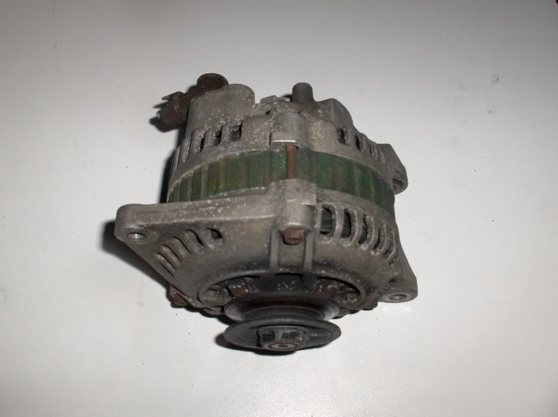
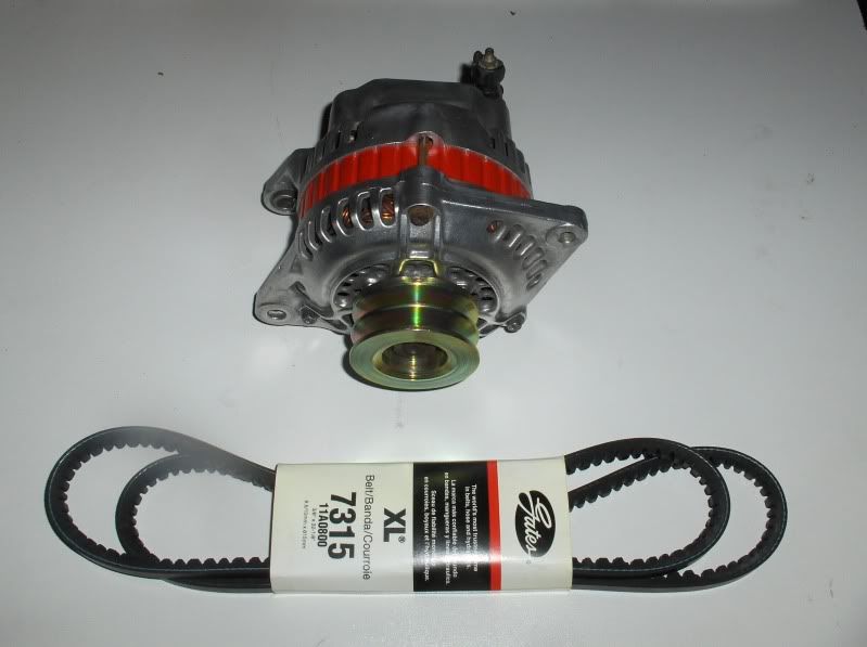
After posting the before and after I now see the bolts that hold the two housings together need a cleaning. I hit the housings quickly with a wire wheel, not a full polish. I couldn't pick it up well w/the camera but it looks alot better in person.
And as a heads up... Having a spare alt helped me big since the plastic on the brushes inside was so brittle it cracked when disassembling the first one.

Thread
Thread Starter
Forum
Replies
Last Post
Captain Hook
2nd Generation Specific (1986-1992)
13
Oct 4, 2015 06:35 PM