
Home made exhaust manifold

Thread Starter
Full Member
Joined: Jul 2007
Posts: 234
Likes: 0
From: South Africa
Home made exhaust manifold
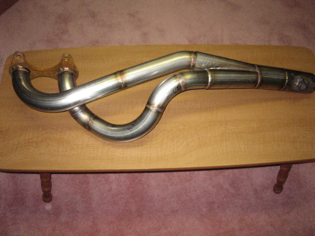
Ok my exhaust manifold is almost done, the lengths are matched, an ID of about 1.9" mandrel bent piping.
Old exhaust manifold was junk, smaller ID, crush bent with only one bend per pipe so lengths were wayyyy off and way too long.
This new manifold should unleash the power of my bridgeport especially considering the center mufflers fallen to pieces which will now be removed and replaced with a megaphone.

Thread Starter
Full Member
Joined: Jul 2007
Posts: 234
Likes: 0
From: South Africa
What is wrong with the collector? i managed to get the pipes to merge with the collector smoothly at the same angle as the inlets of the collector, actually very happy with how smoothly i got them to merge compared to other collectors i have seen. You cant really see in the pic but its quite a nice smooth collector merging at about 30 degrees which is what racing beat recommends.

Thread Starter
Full Member
Joined: Jul 2007
Posts: 234
Likes: 0
From: South Africa
Primary length is about 30" its a bit long but that about as short as i could go and keep the lengths matched, bare in mind old primaries were about 50" long, collects into a 2.4" id pipe and will megaphone out to my 3" mandrel bend exhaust system.
Trending Topics

Thread Starter
Full Member
Joined: Jul 2007
Posts: 234
Likes: 0
From: South Africa
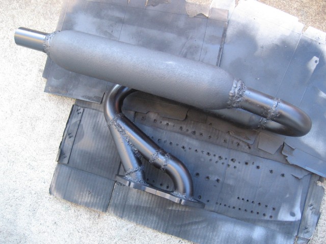
Some more pics. I have also included some pics of the remains of the old header and resonator/pre-silencer. As you can see, old header was far from adequate and resonator was screwed. I'm quite proud of the header considering it cost me 30$ worth of material, and $10 on tool rental to make  . Even with the crappy header and broken pre-silencer I was making 192WHP with this setup and hadn't even finished tuning. Ive made various other improvements to my intake, air filter's etc as well. so I'm eager to get it on the dyno again once ive finished up. Must scavenge around for a megaphone now and finish up exhaust system.


. Even with the crappy header and broken pre-silencer I was making 192WHP with this setup and hadn't even finished tuning. Ive made various other improvements to my intake, air filter's etc as well. so I'm eager to get it on the dyno again once ive finished up. Must scavenge around for a megaphone now and finish up exhaust system.
What is wrong with the collector? i managed to get the pipes to merge with the collector smoothly at the same angle as the inlets of the collector, actually very happy with how smoothly i got them to merge compared to other collectors i have seen. You cant really see in the pic but its quite a nice smooth collector merging at about 30 degrees which is what racing beat recommends.
Ideally you want your collector to be designed similar to this on here:
http://www.spdexhaust.com/pdfs/Temp_...C%26X-pipe.pdf
The double slip on the top right in that link and is a merge design. This allows the two runners to more smoothly merge together with-in the collector. Later this week I'll post pics of my 20b merge collector that Im currently fabricating.
Last edited by t-von; Oct 20, 2008 at 10:17 PM.


Thread Starter
Full Member
Joined: Jul 2007
Posts: 234
Likes: 0
From: South Africa
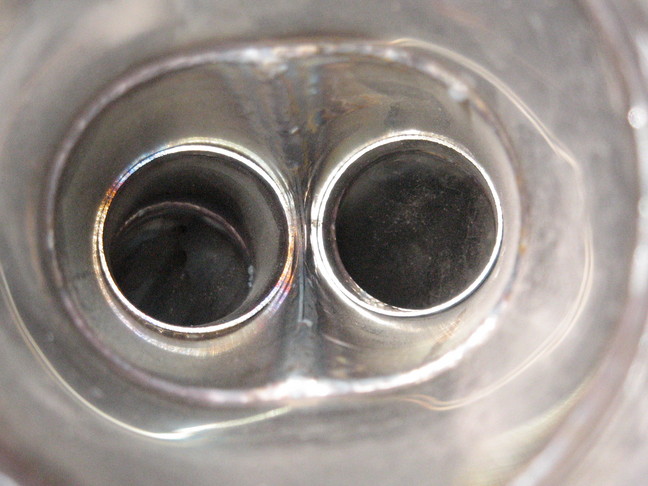
I see. From the looks of it, the inside of my collecter looks almost exactly the same as the inside of your SDJ header's one. The two tubes side by side with the channel down the middle. The angle is similar too so im just going to try it for now. Can always make up a new one later if im not satisfied.
is this a picture looking inside your collector?
If so i would alteast take a die grinder and smooth things out in there as much as possible. also the longer the merge the better from what I've read around. If you note, they merge from the third piece from the last bit on my picture .. about 6" long or so. Also if you're going to be doing a collector, the second piece from the bottom, not sure if you noticed or not, but its actually a bit flattened where the 2 pipe connect to keep a smoother transition. I draw them up on the computer to get the correct cross area then cut the excess there, so that when I flatten out the other pipe it fits right in without any drama.
Hope this info helps
Last edited by dj55b; Oct 21, 2008 at 10:26 AM.
Guys, how should I collect the 2 tubes on the Disassembled Road Race Header Kit from Racing Beat??
I wonder if I have to use the little square part next to the U bend tube for collecting the 2 other tubes ?
Thanks.
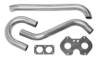
I wonder if I have to use the little square part next to the U bend tube for collecting the 2 other tubes ?
Thanks.
 Thanks.
no that is a pic of his broken pre-silencer
is this a picture looking inside your collector?
If so i would alteast take a die grinder and smooth things out in there as much as possible. also the longer the merge the better from what I've read around. If you note, they merge from the third piece from the last bit on my picture .. about 6" long or so. Also if you're going to be doing a collector, the second piece from the bottom, not sure if you noticed or not, but its actually a bit flattened where the 2 pipe connect to keep a smoother transition. I draw them up on the computer to get the correct cross area then cut the excess there, so that when I flatten out the other pipe it fits right in without any drama.
Hope this info helps
If so i would alteast take a die grinder and smooth things out in there as much as possible. also the longer the merge the better from what I've read around. If you note, they merge from the third piece from the last bit on my picture .. about 6" long or so. Also if you're going to be doing a collector, the second piece from the bottom, not sure if you noticed or not, but its actually a bit flattened where the 2 pipe connect to keep a smoother transition. I draw them up on the computer to get the correct cross area then cut the excess there, so that when I flatten out the other pipe it fits right in without any drama.
Hope this info helps
Are you referring to me or to someone else ? :P can you explain a bit more what did you mean exactly ? Thanks.
Thanks.
I kept my transitions as smooth as possible but had to sacrifice a couple inches out of one of the runners due to limited space reasons. The welds look lumpy but are good on the inside (no burn-through lumps or anything ugly like that).
It may not look it, but the short runner actually exits the engine fairly straight before it gently curves into a correct 30� collector. The mandrel u-bends should keep velocity as high as possible (compared to crush bent stuff) and was the only solution in my limited amount of space in the back of a rotary baja project.

It may not look it, but the short runner actually exits the engine fairly straight before it gently curves into a correct 30� collector. The mandrel u-bends should keep velocity as high as possible (compared to crush bent stuff) and was the only solution in my limited amount of space in the back of a rotary baja project.