FB Rear Suspension Geometry Problems/Options/Solutions
 12-05-10, 02:37 PM
#176
Full Member

Join Date: Nov 2010
Location: vermont
Posts: 64
Likes: 0
Received 0 Likes
on
0 Posts
thanks the ft end needed its own thread!
 12-05-10, 02:45 PM
#177
Old [Sch|F]ool
My current 3-link isn't radically different upper vs. lower, but I did try equal length/parallel arms before and hated it. Kept shortening the link and lowering the front pivot until I ran out of room, basically.
My upper link is a 14.5" Afco 3/4" thread threaded sleeve, with Summit 5/8" hole rod ends. I went for Teflon lined and they still squeak and clatter and make all sorts of racket. I'd hate to have them in every link.
The front pivot is basically on the floor immediately behind the crossmember, the rear pivot is 4-4.5" above the top of the diff. I forget exactly how high it is, but it will come a couple inches through the floor, which is why I had to cut the floor out clear back to the spare tire well. I never did make a box to cover it, there's just a piece of truck mudflap held down by bungees. I braced the snot out of everything but I think I crushed/ovalled the rearend housing, as there's a gap in the middle of the banjo right now, but only on the driver's side. Looks like I get to find another rearend housing if I can't straighten it out.
Between that, and the Panhard rod (1" below axle centerline), I have enough rear bite that I had to go to 200lb springs in the rear for the front end to do anything useful. The funny/scary thing is, even with springs that stiff in the back, it still has tremendous bite.
Disclaimer: I run 25.5" diameter tires on rough dirt/grass/gravel. Your mileage may vary...
Found a progress pic.
12-05-10, 05:16 PM
#178
Moderator
iTrader: (3)
Join Date: Mar 2001
Location: https://www2.mazda.com/en/100th/
Posts: 30,816
Received 2,586 Likes
on
1,837 Posts
Thanks. The box did come out rather large but that was done to make service and adjustment easy. Remember that the cover has to be big enough to allow for the removal of hardware and the use of tools. I welded the cover in place for fire safety. Also, since it is serviced from below I off set the link so that the drive shaft wouldn't be in the way. There is notthing worse than a racecar that is hard to work on.
The mounting bracket is high to accomodate the location of the mount on the rear axle as well an adjustable ride height that will let the car get pretty low. Also to allow for a very wide range of adjustment at the chassis. I put this same suspension on a Mustang and was very suprised at some of the arm angles I had to use to make the car work in certain situations.
The mounting bracket is high to accomodate the location of the mount on the rear axle as well an adjustable ride height that will let the car get pretty low. Also to allow for a very wide range of adjustment at the chassis. I put this same suspension on a Mustang and was very suprised at some of the arm angles I had to use to make the car work in certain situations.
12-05-10, 05:19 PM
#179
Moderator
iTrader: (3)
Join Date: Mar 2001
Location: https://www2.mazda.com/en/100th/
Posts: 30,816
Received 2,586 Likes
on
1,837 Posts
the factory car has parallel 4 links, they used what looks to the untrained eye as the SA bin reinforcement as a mount for the upper control arms.
doing the parallel equal length 4 link is common in the hatchi world too
12-05-10, 06:58 PM
#180
I have seen that done in an SCCA GTL Miata - the cell sits next to the driver. Kinda scary if you ask me but it sure would help with weight distribution.
From my perspective if you are running suspension elements in the interior of the car in a wheel to wheel racing class care needs to be taken to create a fire barrier. I was unfortunately at an SCCA club race in which a driver died in part to fire. He was not able to get out his car and fire crews could not get to him fast enough. I have seen allot of fires at club races and no matter how well a club race is covered by safety workers it takes time to get proper fire fighting equipment to a car. A fire barrier buys you time.
12-05-10, 07:06 PM
#181
Full Member

so no ones really answered my question about adding longer/adjustable upper control arms. and changing where the watts link mounts to the chasis to compensate for the car being lowered....in my head it seems like it would at least be an improvement.
12-05-10, 08:40 PM
#182
Old [Sch|F]ool
j9fd3s - I only ever played with 3 links. The first one I did was kind of an emergency measure after the wheelwells fell apart. This chassis has solid wheelwells but the 3-link works so well! It also takes a lot less fab work relative to making the boxes for a 4-link.
ayo513 - the only issue with relocating the Watts is that any 4-link that does not have parallel arms will have its own defined roll center. (Did you know that you can, in fact, drive a 1st-gen around just fine with no Watts at all, provided that the upper links are in good shape?) Any additional lateral location must coincide with the 4-link's roll center or you will get roll bind. The main problem with the Mazda 4-link is that the upper links just plain suck!
3-links also have a self-defined roll center but it's a lot more "fluid". It doesn't cause a bind if you move the lateral location around height-wise, but it does change roll steer effects. A 3-link with the stock Watts will make that very noticable
4-links are, simply put, harder to make work perfectly. That's why you see people running 3-links, or torque arms, or "Lotus links" (AKA A-frame), or even truck arms.
I still can't quite figure out some of the circle track suspensions out there. Decoupled torque arms, reversed upper links, brake reaction links... and everything has springs or elastomerics to fine-tune everything further!
- Pete (Speedway Catalogs are my pr0n)
12-05-10, 08:42 PM
#183
In short, longer upper links in the stock location would fix nothing. It's cheaper and lighter and you get a lower roll center to go with a panhard then redesign a watts link.
on a side note: got my panhard mount welded in. Look's like crap, but it works, really well.
 12-05-10, 09:12 PM
#184
Old [Sch|F]ool
Eh, it looks a lot nicer than mine.
Mine is a piece of slapper bar (think leaf-spring traction aid) welded to the right chassis rail (reinforced with plate) with a couple tabs welded to it. The axle side is a piece of Watts link welded near the shock. To make it double shear, I added a doubler plate that had to be removable, and I later realized that the doubler's second stud was interfering with the shock, and... well it's not pretty.
Anyway, I drilled a large hole in the left side chassis rail (facing down) for clearance for a nut I encaptivated (zap zap zap) to a beefy washer. That nut was for the bolt for the Panhard brace, which is just a piece of 1x1 square stock that I mashed flat at the ends. The other end bolts to the outside of the Panhard bracket, using the same bolt as the bar.
For extra paranoia factor, I braced *that* to the front of the spare tire well using another piece of mashed 1x1.
The bar itself is a Watts link that I'd lengthened using my favorite suspension material: galvanized water pipe. Hold your breath when welding
Looks absolutely disgusting. On the other hand, it withstands side hits heavy enough to yank the inside wheels a foot off the ground, so it's strong enough.
12-05-10, 09:14 PM
#185
Full Member
what i was saying was to modify the upper control arms to correct pinion angle. and "re" mount the watts link rods to correct the geometry. im saying change the location the stock bars mount to the body.
12-05-10, 09:23 PM
#186
Old [Sch|F]ool
Maybe strange, but I never had pinion angle issues that weren't related to floor issues.
You won't be able to relocate the Watts to correct anything. That's the problem. The 4-link's design HAS the roll center that high. Lowering the car makes the roll center even higher. The only thing you'd be able to do to "correct" anything would involve massive relocation of all mounting points, easiest way to do this is to relocate them on the axle housing.
Or you could just not lower the car, and use tires that are in the 23" diameter range.
12-05-10, 09:36 PM
#187
Full Member
ok now im getting it, im not very knowledgeable with suspension geometry, so im trying my best to figure things out. What if you centered the watts link and mounted it low on the axle housing?
12-06-10, 10:40 AM
#188
Moderator
iTrader: (3)
Join Date: Mar 2001
Location: https://www2.mazda.com/en/100th/
Posts: 30,816
Received 2,586 Likes
on
1,837 Posts
they also moved the watts link pivot so its on the bottom of the axle
12-06-10, 02:14 PM
#189
Maybe strange, but I never had pinion angle issues that weren't related to floor issues.
You won't be able to relocate the Watts to correct anything. That's the problem. The 4-link's design HAS the roll center that high. Lowering the car makes the roll center even higher. The only thing you'd be able to do to "correct" anything would involve massive relocation of all mounting points, easiest way to do this is to relocate them on the axle housing.
Or you could just not lower the car, and use tires that are in the 23" diameter range.
You won't be able to relocate the Watts to correct anything. That's the problem. The 4-link's design HAS the roll center that high. Lowering the car makes the roll center even higher. The only thing you'd be able to do to "correct" anything would involve massive relocation of all mounting points, easiest way to do this is to relocate them on the axle housing.
Or you could just not lower the car, and use tires that are in the 23" diameter range.
12-06-10, 09:20 PM
#190


This is a four link on an E Production FB. The upper links are approx as long as the lowers. They connect to rear axle using the factory mount. This car has a panhard bar instead of a watts. If an alternate watts is used it would be better to mount it to the rear of the axle housing. By the way, this suspension works very well. Note that the lower contiol arm mount is lowered 2.5" below the stock point on the axle to compensate for the lowered ride height
About 15 years ago I helped buld an FB racecar that used the stock 4 link and the stock watts link. Every bushing was replaced with a spherical bearing. The result was not very good. We broke the factory lower control arms and the watts link pin on the axle housing. The lower arms broke due to bind and the watts pin broke because it is too week. The factory Watts setup is a street part.....a non-starter for racing.
12-07-10, 01:40 PM
#191

I'm going to post this in both thread because I thinks it has some good info.
http://www.gtcars.ca/online/car-care...need-know.html
I know its not FB related but still.
http://www.gtcars.ca/online/car-care...need-know.html
I know its not FB related but still.
12-07-10, 09:54 PM
#192
Full Member
Join Date: Nov 2010
Location: vermont
Posts: 64
Likes: 0
Received 0 Likes
on
0 Posts
You mean like this?
This is a four link on an E Production FB. The upper links are approx as long as the lowers. They connect to rear axle using the factory mount. This car has a panhard bar instead of a watts. If an alternate watts is used it would be better to mount it to the rear of the axle housing. By the way, this suspension works very well. Note that the lower contiol arm mount is lowered 2.5" below the stock point on the axle to compensate for the lowered ride height
About 15 years ago I helped buld an FB racecar that used the stock 4 link and the stock watts link. Every bushing was replaced with a spherical bearing. The result was not very good. We broke the factory lower control arms and the watts link pin on the axle housing. The lower arms broke due to bind and the watts pin broke because it is too week. The factory Watts setup is a street part.....a non-starter for racing.
thanks for the input. planing on useing a setup like this. was planing to build something more complicated, but seems like this is just the best setup one can build in he garage for themselves and make a big difference in the way the car handles.
12-07-10, 11:34 PM
#193
I'm going to post this in both thread because I thinks it has some good info.
http://www.gtcars.ca/online/car-care...need-know.html
I know its not FB related but still.
http://www.gtcars.ca/online/car-care...need-know.html
I know its not FB related but still.
12-08-10, 11:05 PM
#194
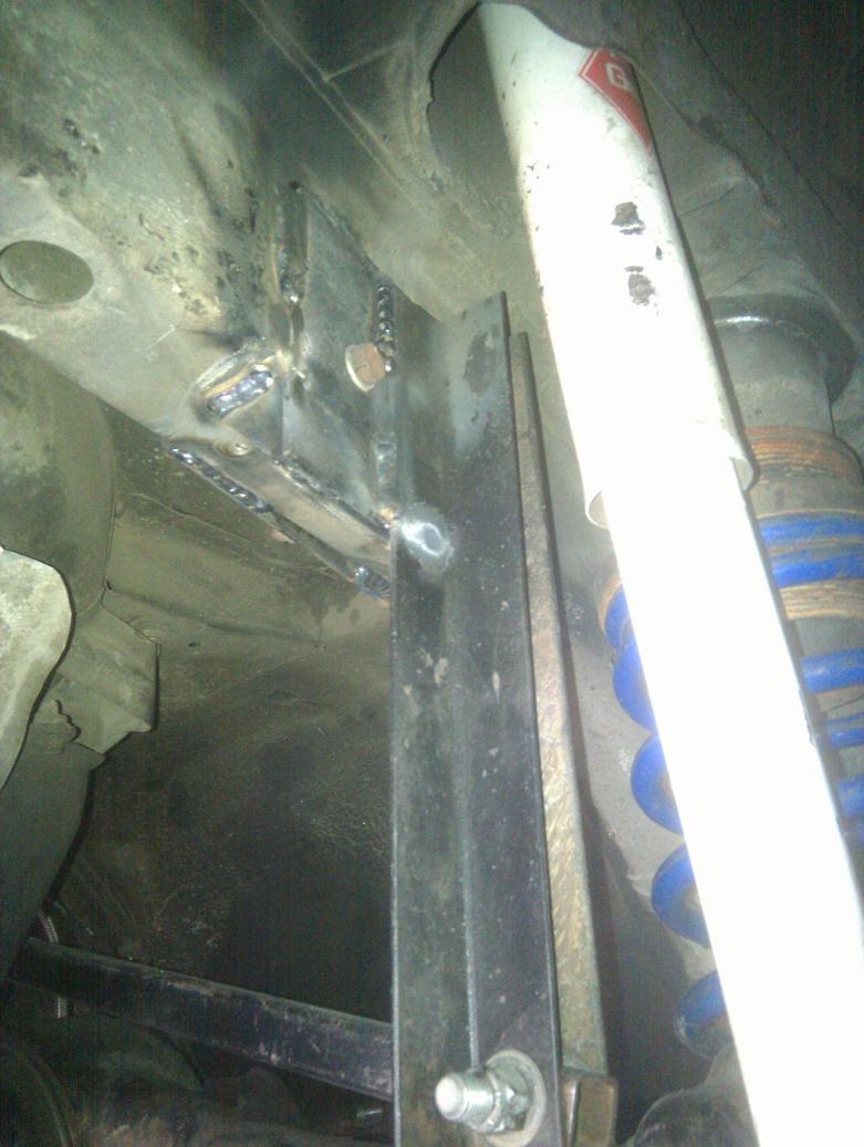
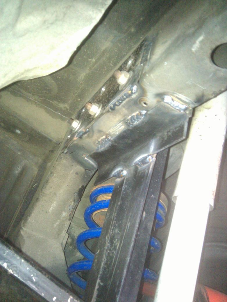
Here is the rearend housing I built for my STU car.
Lower control arm mounts are 1.5", 3" and 4.5" lower than the stock mount. The shock mounts are 2" lower than stock. The factory watts mount has been cut off as well as the right side upper control arm mount. The left side upperr control arm mount has been trimed down and used to help support the panhard mount. The panhard mount is braced to the back of the rearend housing. A third link mount is attached to the top the rearend. The factory spring pads were cut off and replaced with adjustable mounts for 2.5" coil over springs.
Rear end housing from the right side

Panhard mount detail

Panhard mount detail

Lower control arm mount

Third Link mount

Lower control arm mounts are 1.5", 3" and 4.5" lower than the stock mount. The shock mounts are 2" lower than stock. The factory watts mount has been cut off as well as the right side upper control arm mount. The left side upperr control arm mount has been trimed down and used to help support the panhard mount. The panhard mount is braced to the back of the rearend housing. A third link mount is attached to the top the rearend. The factory spring pads were cut off and replaced with adjustable mounts for 2.5" coil over springs.
Rear end housing from the right side
Panhard mount detail
Panhard mount detail
Lower control arm mount
Third Link mount
12-09-10, 07:06 PM
#196
Nothing wrong with the G Force part - it works very well. I just wanted the longest possible panhard bar.
I am pretty certain that the G-Force bar clears the stock tank.
12-09-10, 09:45 PM
#197
Yeah the G force panhard clears the stock tank with no issues. I had one on my T2 FB for a while but the noise for the heim joints was too much for a daily driver (for me at least). I've been thinking about making my own but with poly bushings. This thread has given me a lot of good ideas!
12-09-10, 10:20 PM
#198
Yeah the G force panhard clears the stock tank with no issues. I had one on my T2 FB for a while but the noise for the heim joints was too much for a daily driver (for me at least). I've been thinking about making my own but with poly bushings. This thread has given me a lot of good ideas!
12-13-10, 08:20 PM
#200
Thanks. The brackets are from All Star products - they are predrilled 5/8" holes on an arc that is pretty close to what you need for an rx7. I got them from a local circle track shop - online they are sold by Pitstop USA. I used the stock mounting holes (drilled out) and a couple 5/8 bolts to line everything up.