FB Rear Suspension Geometry Problems/Options/Solutions
 12-21-10, 10:25 PM
#226
That 3 piece design is prety close to what you get from energy suspension for the FB.
I made a mold and played around with different durometers, and ended up softening the centers just a tad.
I am happy with the results and run them in all 4 rear links.
While not optimal, I find it much better than stock and I dont seem to run into the bind commonly associated with full polys in the rear.
 12-22-10, 11:46 AM
#227
That 3 piece design is prety close to what you get from energy suspension for the FB.
I made a mold and played around with different durometers, and ended up softening the centers just a tad.
I am happy with the results and run them in all 4 rear links.
While not optimal, I find it much better than stock and I dont seem to run into the bind commonly associated with full polys in the rear.
I made a mold and played around with different durometers, and ended up softening the centers just a tad.
I am happy with the results and run them in all 4 rear links.
While not optimal, I find it much better than stock and I dont seem to run into the bind commonly associated with full polys in the rear.
12-22-10, 12:11 PM
#228
Been here since dirt...
Join Date: Jan 2009
Location: AZ
Posts: 327
Likes: 0
Received 0 Likes
on
0 Posts
As I mentioned in an earlier post, I own a Fox Mustang (85 GT - 4 Eye) street car. While researching the aftermarket for this car I came across and interesting idea for poly bushings. 3 Piece Poly bushings that consists of a hard center bushing surrounded by two softer bushings (one one each side). The theory is that the softer bushings allow the control arm to twist as the suspension moves while the hard center bushing resists compression and helps the car maintain traction.
The hard center bushing is actual round on this design
http://www.hotpart.com/shop/index.ph...ct_images&p=43
The hard center bushing is actual round on this design
http://www.hotpart.com/shop/index.ph...ct_images&p=43
Thanks!
GD
Last edited by gawdodirt; 12-22-10 at 12:19 PM.
12-22-10, 12:27 PM
#229
Senior Member
Join Date: Dec 2006
Location: Sylva, NC
Posts: 272
Likes: 0
Received 0 Likes
on
0 Posts
Hey guys, I was looking for some videos of suspension articulation and found this:
http://www.youtube.com/watch?v=HzoijYQeyY8
Not really the kind we are discussing but still interesting I think.
Could we utilize this setup to perform better than stock?
http://www.youtube.com/watch?v=HzoijYQeyY8
Not really the kind we are discussing but still interesting I think.
Could we utilize this setup to perform better than stock?
12-22-10, 02:09 PM
#230
Moderator
iTrader: (3)
Join Date: Mar 2001
Location: https://www2.mazda.com/en/100th/
Posts: 30,816
Received 2,588 Likes
on
1,838 Posts
maybe this is a good time to go backwards and clarify the issues we are trying to fix in the rear suspension, before we cut the back half of the car off....
1. the stock roll center is too high. mazda's solution in 79 was to make an axle housing with the watts link pivot on the bottom, if you wanted to duplicate, afco makes a plate that goes between the pumpkin and axle housing that holds the pivot. a panhard is a good solution as well. easy fixes
2. the stock link arrangement binds in roll. not an easy fix! the factory fix is to have different upper link attachment points on the axle, and allowing longer upper links with rod ends. later they moved the pivot point in the body. the 3 link works too. are these the best solutions? the Ae86 corolla has a similar 4 link/panhard and they do not have the same problems we do.
3. the axle housing is weak with big power (260hp/2200lbs). they bent em in 1979, i see no reason they wont still be weak in 2010!
anything else?
12-22-10, 04:38 PM
#231
Been here since dirt...
Join Date: Jan 2009
Location: AZ
Posts: 327
Likes: 0
Received 0 Likes
on
0 Posts
maybe this is a good time to go backwards and clarify the issues we are trying to fix in the rear suspension, before we cut the back half of the car off....
1. the stock roll center is too high.
2. the stock link arrangement binds in roll. not an easy fix! the 3 link works too. are these the best solutions? the Ae86 corolla has a similar 4 link/panhard and they do not have the same problems we do.
3. the axle housing is weak with big power (260hp/2200lbs). they bent em in 1979, i see no reason they wont still be weak in 2010!
anything else?
( I'm keen on this because while I worked at GM, I was lucky enough to work with Satchell while he worked on the 1983 Fiero GTU program. Had time to talk about many things suspenion related.)
A WORD FROM THE INVENTOR
After I originally mailed this newsletter, I received a note from Terry Satchell, who originated the
suspension bearing his name. He contributes some interesting background on the history of the
design and his views regarding its advantages. He writes:
…I had done a Lotus Super 7 type rear for a Trans Am car where the lower A-arm has a pivot under
the axle with two upper longitudinal arms. After running it for a year we kind of got the impression
that the rear roll center was too low, it being at the pivot of the A-arm to axle joint. Since I had
designed four bar link rear axle suspensions for General Motors for several years, I knew how to
analyze them and create what I wanted. I wanted a geometry with a roll center basically midway
between the bottom of the axle housing and drive axle centerline. By reversing the lower arms to
converge to the center ahead of the axle I was able to achieve a good geometry. It worked well on
the track, and in fact one of the neat parameters was that the anti-squat increased on the inboard
wheel with roll giving a tightening effect on power that helps corner exit.
I did a version of this geometry for Herb Adams who did all of Walker Evans truck suspensions and
they were very happy with it. They in particular liked the anti-squat difference across the back with
roll on throttle for their Stadium racing trucks.
Since then I have done several versions for various disciplines and now there is a company in
Pennsylvania that provides aftermarket conversions for Mustangs, Camaros and Firebirds to get rid
of the leaf spring suspension and use this four bar link with coilovers.
I have also had success with several of the "Locost" builders using it. [The Locost is a kit car
similar to a Lotus 7.] One in particular used it to control his deDion beam.
Just thought you might like to know a little more of the story.
By the way, I never intended to put my name to this version of a four link. Herb Adams named it in
one of his books and that is how it got started being call the Satchell Link.
As far as the strength, what was it that bent/broke?
GD
Last edited by gawdodirt; 12-22-10 at 04:41 PM.
12-22-10, 06:49 PM
#232
Old [Sch|F]ool
I don't know if that is the proper, engineering-speak term for it, but it's the term as I've seen it, and it's a useful term.
The problem has absolutely nothing to do with the bushings, although soft bushings can be used to mask the problem. The Foxes used large oval bushings in the lower control arms (axle end, I think) to allow for the geometrical imperfections.
The problem is that, in suspension motions that involve one wheel bump or droop, the links on one side will want to rotate the axle one way and the links on the other side will want to rotate the axle the other way. Being that the axle cannot twist (that much), what ends up happening is that you get a big gob of added, non-linear roll stiffness, dependent on how compliant the bushings are and how flexible the rear axle and body brackets are.
For the ultimate example of the problem, try to articulate a ladder bar suspension.

I know that a WELL DONE Satchell or any other kind of 4-link CAN work properly. The allure of the 3-link is that the very nature of the device means that, no matter how much you screw up the geometry in other ways, you can't screw it up so that the suspension will bind up.
I did two three-links and both times I wondered why I didn't do it sooner. The interesting/perverse thing is, having a suspension that can move that freely means that you can/have to run a lot more roll stiffness. The difference is that it's a much more linear feel, instead of understeer that quickly ramps up into snap oversteer unless you stiffen BOTH ends to the point where they barely move and tune handling strictly with alignment and tires.
12-24-10, 10:28 PM
#233
Been here since dirt...
Join Date: Jan 2009
Location: AZ
Posts: 327
Likes: 0
Received 0 Likes
on
0 Posts
Thanks for your thoughts well explained. I have modeled a paralell 4 link and if you have one side move and the other doesn't in a turn, if the bars are level at ride height, the side that moves will shorten the wheelbase as the bars move through their arcs. Minor amounts but will nonetheless. This is where the 4 link systems would work over the three link. The three link will not have the outboard influence of the suspension movement at the wheel. More predictable but no added beneficial effect to turn the car out of a turn. This is what Satchell described as tightening in a turn. The droop on the inboard wheel will give the effect of turning the axle in a rear steer effect to help pivot the car. Taking out the articulation makes it more prone to stay straight. Use the roll to help pivot the chassis.
Of course , the longer the axle links, the less effect it has. So longer bars might not be a good thing. Design the length with the usage in mind. The stiffer the suspension, with less travel, the shorter the links should be.
In a few of the last suspension systems I worked on, the lower arm was 68" long. That truck had 32" of rear travel. With about 5 inches of travel, maybe 16" links would work.
Good topic.
Merry Christmas!!
Last edited by gawdodirt; 12-24-10 at 10:43 PM.


 01-24-11, 03:06 AM
#235
BUY MY PARTS!!!
Thread Starter
iTrader: (5)
Join Date: Nov 2004
Location: Blacksburg, VA
Posts: 428
Likes: 0
Received 0 Likes
on
0 Posts
Just wanted to jump back in here and say AWESOME! glad to see all the info. I still haven't changed anything on my car yet- gonna try to make it until the rear diff finally gives out then make a decision on what to do. Thanks guys!
01-31-11, 02:02 PM
#236
Junior Member

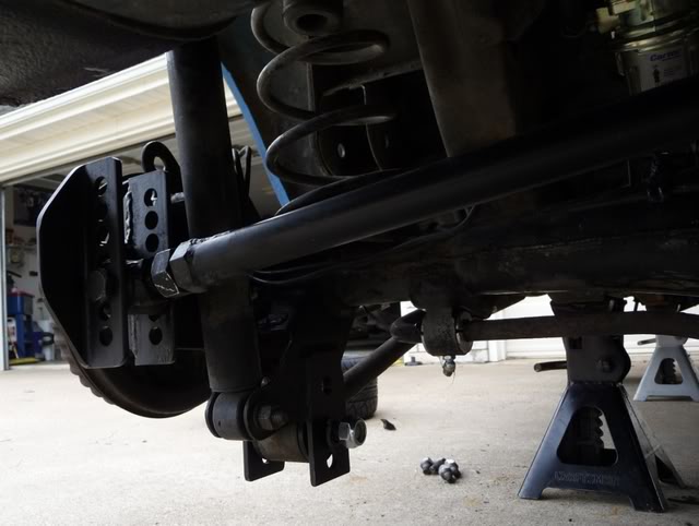
Hey guys, been lurking here for a while absorbing knowledge and working on my '84 FB that I race in 24 Hours of Lemons. Here's some information and pictures of my latest work- custom panhard bar and 3-link, among other things.
Since Lemons rewards DIY over opening up your wallet I decided to do all my suspension mods cheaply by repurposing old parts and using cheap stock materials. I built the panhard bar and 3-link from the remains of the stock watts link rod ends, some 1" DOM tubing, and a bit of 1.5"angle to make the various mounts and braces. I made my own urethane bushings for the entire suspension from the McMaster 94 durometer casting urethane and poured it into custom nylon molds. Additionally, I turned out some grease-able aluminum swaybar mounts and welded some extensions to the lower arm brackets on the axle in attempt to correct the wonky geometry.
At our last race we were getting really bad inner wheel spin and I could feel the car "standing up" on the rear axle through the corners. The car is making decent power now with my Sterling Nikki clone and dual side exhaust (stock 12A otherwise) so it was time to work out the geometry. I built in a bunch of adjustment to all the new linkage so hopefully I can tune it all in to my liking later this month. If all these mods work we should be in good shape come this April.
Thanks, and enjoy.
 02-09-11, 12:42 PM
#241
Junior Member
I used a 110V MIG welder from Northern (#MIG135) for welding in the mounts and brackets to the chassis. It does fine up to 3/16 steel and lays down a smooth bead. The key is to use gas and solid wire. Flux-core is junk and should never be used for anything structural.
For the more detailed stuff I always use my TIG. It's the Lincoln Precision 225. This baby does it all and I have all the confidence in the world with the welds it lays down.
For the more detailed stuff I always use my TIG. It's the Lincoln Precision 225. This baby does it all and I have all the confidence in the world with the welds it lays down.
 07-22-11, 06:00 AM
#243
Old [Sch|F]ool
Did you shave the axlehousing? The ring gear bump looks a lot flatter than I remember.
I'll take pics if I swap in another housing to replace this one. But I may just end up going with a 3rd-gen F-body rear and use the existing link/Panhard mounts, and adapt the torque arm..
I'll take pics if I swap in another housing to replace this one. But I may just end up going with a 3rd-gen F-body rear and use the existing link/Panhard mounts, and adapt the torque arm..
07-22-11, 09:18 AM
#244
Did you shave the axlehousing? The ring gear bump looks a lot flatter than I remember.
I'll take pics if I swap in another housing to replace this one. But I may just end up going with a 3rd-gen F-body rear and use the existing link/Panhard mounts, and adapt the torque arm..
I'll take pics if I swap in another housing to replace this one. But I may just end up going with a 3rd-gen F-body rear and use the existing link/Panhard mounts, and adapt the torque arm..
03-05-12, 11:21 PM
#245
BUY MY PARTS!!!
Thread Starter
iTrader: (5)
Join Date: Nov 2004
Location: Blacksburg, VA
Posts: 428
Likes: 0
Received 0 Likes
on
0 Posts
Hope this thread has helped some people understand the issue our car has!!!
As for me, I'm still trying to decide the best solution for my current FB- 350hp/tq and a Chrysler 8 3/4" rear end, which currently has the stock 83 Axle mounts/watts welded to it, so for now, its just a bigger, stronger axle with all the same problems!!!
As for me, I'm still trying to decide the best solution for my current FB- 350hp/tq and a Chrysler 8 3/4" rear end, which currently has the stock 83 Axle mounts/watts welded to it, so for now, its just a bigger, stronger axle with all the same problems!!!
10-08-12, 07:44 AM
#246
Im having trouble with my "85 s3 tailshaft and yoke hitting the floor under hard acceleration.
Its gouged a decent scar into the floor.
Its running a worked t2 motor and is lowered. Torsen diff center. Standard trailing arms and watts link arrangement. It has superpro urethane everywhere, even the upper trailing arms*
It looks like the front of diff is twisting up under power.
Are there any cheap and easy ways of rectifying this?
Would redrilling the trailing arm mounts higher on the car body restore geometry to a lowered car?
*this was to remedy the yoke smacking into the floor, but didnt work. Now one of the upper trailing arm mounts has snapped clean off the diff housing, might have something to do with urethane on the uppers? Anyway I"m thinking about drilling the UTA urethane for a bit more flex this time(good idea or bad?) cos we cant get rubber bushes here.
Last edited by WANKfactor; 10-08-12 at 07:52 AM.
10-08-12, 09:08 PM
#247
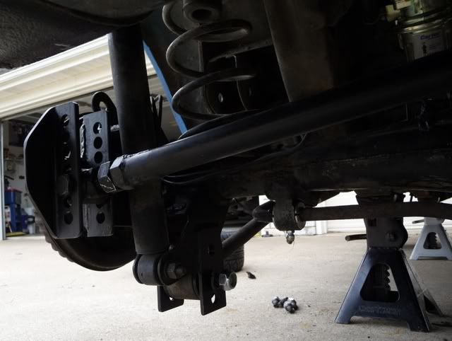
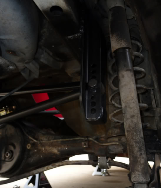
Im thinking about lengthening the lower trailing arm mounts on the diff Like Strebor here^^, and redrilling the upper arm mounts higher on the car body, welding in plates if neccissary.
Do you guys reckon that would work?
Also, looking at the std watts arrangement, im thinking about lengthening the short end of the central pivot, to try and gain symetry, but will have to wait till i get my diff back from the diff shop so i can check it properly that there is room under there.
Thoughts?
Has this been done? Is anyone making an after market watts link that bolts in?
Any help, input, insight would be appreciated.
Cheers
Last edited by WANKfactor; 10-08-12 at 09:11 PM.
10-08-12, 09:36 PM
#249

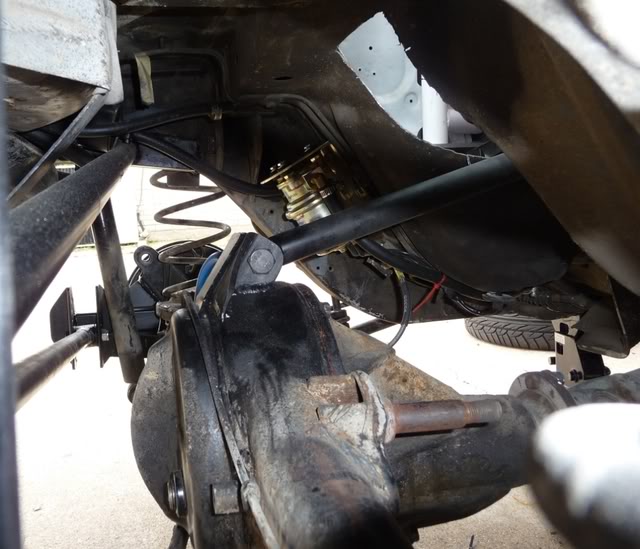
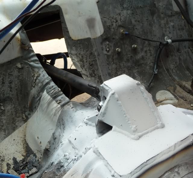
The upper traction bar attaches to the stock upper control arm mount on the axle housing. The other end of the upper traction bar attaches to a mount that is mostly contained in the car. [quote]
Yeah thanks for the reply mate, iv spent a couple of hours skimming through this thread last night and today, great thread by the way!
Not sure if im afan of the trilink, as it looks to me like there will be extra twisting force acting on the diff housing, potentially destroying axle bearings or worse. (my car currently makes 240rwkw or about 330?rwhp and soon to be more)
I was also contemplating doing what mustanghammer here posted^^ see pic, except using two of the shorter watts link arms (the ones with the angled ends) sourced from wreckers, but really im just putting out feelers to find a cheaper, easier way of fixing my problem, and bouncing some ideas around to see what can be done!

[edit] also, i read the link that i think may have been you hyper4mance2k who posted it? on drilling the upper arm bushes and not overtightening the bush bolts, i definately will be trying this on install. (although i was thinking about this before i saw the link, it good to know others have alresdy done it with good results!
Last edited by WANKfactor; 10-08-12 at 09:52 PM.
10-09-12, 10:20 AM
#250
Moderator
iTrader: (3)
Join Date: Mar 2001
Location: https://www2.mazda.com/en/100th/
Posts: 30,816
Received 2,588 Likes
on
1,838 Posts
so the bushings used in them need to be really flexible. the racing parts were just stock with an adjuster for length.
so anything you can do to make it more flexible is good, the tri link simply gets rid of these links