
FB Rear Suspension Geometry Problems/Options/Solutions


I though with the rack you lost turning radius and steering angle... both thing's I'm not willing to compromise on especially considering two of the FB's drawbacks you forgot to mention was its already poor turning circle and lack of steering angle.


You are correct, you do lose a little turning radius, (not a lot), but it is not because of the rack, it is because the inside of the tire strikes the sway bar, which in the respeed setup is thicker than stock. I am running 205-50-15s, not sure of the exact offset,(its close to stock). If you have more narrow tires / different offset you would have a sharper turning radius.

Its the ackerman that really kills it.
If it wasnt so tight and awesome at speeds I would really dislike the conversion. I find it much harder to get out of a tight driveway now
Come spring I plan to explore some modifications to restore proper ackerman geometry... Does'nt seem like an easy task with the stock tie rod ends though.
Maybe some turn in spacers put on the opposite sides from a stock setup?
Longer control arms?
Anyone else try to remedy that issue with the respeed setup??
I would absolutely love it if I could restore the turning radius.
Edit: Sorry to derail the rear suspension thread.. someone start a front end thread!!! haha
I lost a **** TON of steering radius when I installed the respeed rack and pinion.
Its the ackerman that really kills it.
If it wasnt so tight and awesome at speeds I would really dislike the conversion. I find it much harder to get out of a tight driveway now
Come spring I plan to explore some modifications to restore proper ackerman geometry... Does'nt seem like an easy task with the stock tie rod ends though.
Maybe some turn in spacers put on the opposite sides from a stock setup?
Longer control arms?
Anyone else try to remedy that issue with the respeed setup??
I would absolutely love it if I could restore the turning radius.
Edit: Sorry to derail the rear suspension thread.. someone start a front end thread!!! haha
I'll start by saying that I have a huge amount of respect for Billy since he's the only guy out there developing new products for our cars. He also happens to be one of the nicest guys I've dealt with!

However I'm surprised no one else has posted about the issues with the turning radius on the respeed setup. I have the rack and pinion kit on both my FB's and while I absolutly love the feel of the steering while driving, any kind of parking lot/driveway etc is very annoying, to say the least.
I have spoken to Billy about this a few times and basically the fix is to make a new knuckle arm that angles outward (away from the car) this of course requires a bigger wheel as it would hit the stock sized wheels... Apparently taking the stock arms and simply switching them around though will angle it out too much so some modifications would be needed. I've been toying with the idea of experimenting with this, however I haven't gotton around to it.
Anyone else do anything with it?
Also sorry to have gotton off topic

Lives on the Forum
Joined: Jun 2004
Posts: 11,359
Likes: 14
From: Grand Rapids Michigan
My understanding is that the fix is possible (correcting ackerman with the R&P kit),
but would cost some money.
I think that if enough people were interested in a correction, and were willing
to pay the costs, then Billy would provide a solution.
but would cost some money.
I think that if enough people were interested in a correction, and were willing
to pay the costs, then Billy would provide a solution.
I dont care how much it costs! Im in for a solution!! Thats the only bothersome thing about the respeed kit.
No disrespects to Billy!!! Great guy, awesome products! Just a minor issue...
IIRC the tie rod clearance issue is with the brake rotor, and not necessarily the wheel.
I was thinking about looking into a combination of roll center blocks and custom outward angled steering knuckles?
Just not sure about clearances until I get under the car again.
I run 17" wheels so Im sure I can get away with the wheel clearance, just not exactly sure what kinda fabwork its gonna take.. Either way Im determined to remedy this issue!
If someone doesnt beat me to a front suspension thread, Ill make one when Im ready to experiment with the R+P kit.
Cheers!

Full Member
Joined: Nov 2009
Posts: 100
Likes: 0
From: cincinnati oh
As far as the rear end geometry, I was think why not just add longer/adjustable upper control arms, then change where the watts link rods mount to the body. I guess to compensate for lowering the car. Just an idea
Been here since dirt...
Joined: Jan 2009
Posts: 327
Likes: 0
From: AZ
I checked some references to see if I was messed up. I was correct in my assumption that those spacers cannot add steering angle unless it changes the
angle of the steering arm in relation to the spindle. It does alter the roll center giving the effect that it turns in better. Take a read on this page as it does explain it well.
http://www.smithees-racetech.com.au/ackerman.html
For quicker turn in, you cound move the outer tie rod closer to the spindle. But it would most likely be along he same vector and still not adding or changing the Ackerman angle.
Good discussion!
GD
Last edited by gawdodirt; Dec 2, 2010 at 06:45 PM.
I think a slight modification to the design of the steering knuckle the comes with the kit to angle the steering knuckles outward would increase ackerman and shorten the turning radius. All it would take would be for the two holes for the bolts to moved slightly.
It would move the tip of the knuckle out. Wouldnt that help? I have considered asking Billy to sell me two knuckles without the mounting holes so that I can drill them myself.
It would move the tip of the knuckle out. Wouldnt that help? I have considered asking Billy to sell me two knuckles without the mounting holes so that I can drill them myself.

Joined: Mar 2001
Posts: 31,833
Likes: 3,232
From: https://www2.mazda.com/en/100th/
Been here since dirt...
Joined: Jan 2009
Posts: 327
Likes: 0
From: AZ
I dont care how much it costs! Im in for a solution!! Thats the only bothersome thing about the respeed kit.
No disrespects to Billy!!! Great guy, awesome products! Just a minor issue...
IIRC the tie rod clearance issue is with the brake rotor, and not necessarily the wheel.
I was thinking about looking into a combination of roll center blocks and custom outward angled steering knuckles?
Just not sure about clearances until I get under the car again.
I run 17" wheels so Im sure I can get away with the wheel clearance, just not exactly sure what kinda fabwork its gonna take.. Either way Im determined to remedy this issue!
If someone doesnt beat me to a front suspension thread, Ill make one when Im ready to experiment with the R+P kit.
Cheers!
No disrespects to Billy!!! Great guy, awesome products! Just a minor issue...
IIRC the tie rod clearance issue is with the brake rotor, and not necessarily the wheel.
I was thinking about looking into a combination of roll center blocks and custom outward angled steering knuckles?
Just not sure about clearances until I get under the car again.
I run 17" wheels so Im sure I can get away with the wheel clearance, just not exactly sure what kinda fabwork its gonna take.. Either way Im determined to remedy this issue!
If someone doesnt beat me to a front suspension thread, Ill make one when Im ready to experiment with the R+P kit.
Cheers!
Ok, bear with me here and use your imagination. The Ackerman as it stands has the steering arms angled inward. Correct? So if you want to tighten the Ackerman, heat and bend the steering arms inward and then weld a gusset to maintain the dimension. Now you have more Ackerman. It should turn in faster. Check the bump steer as it will accentuate this. The rack, or relay rod will either have to be moved up or down to remove any bumpsteer,. Or the outer tierod.
Angle the arm outward only will decrease the Ackerman angle.
GD .
Last edited by gawdodirt; Dec 2, 2010 at 11:22 PM.
Ok, bear with me here and use your imagination. The Ackerman as it stands has the steering arms angled inward. Correct? So if you want to tighten the Ackerman, heat and bend the steering arms inward and then weld a gusset to maintain the dimension. Now you have more Ackerman. It should turn in faster. Check the bump steer as it will accentuate this. The rack, or relay rod will either have to be moved up or down to remove any bumpsteer,. Or the outer tierod.
Angle the arm outward only will decrease the Ackerman angle.
GD .
Angle the arm outward only will decrease the Ackerman angle.
GD .
To get proper ackerman they would have to angle outwards and in that case the brake rotor appears to be in the way
Joined: Jul 2002
Posts: 7,301
Likes: 3
From: District of Columbia
I checked some references to see if I was messed up. I was correct in my assumption that those spacers cannot add steering angle unless it changes the
angle of the steering arm in relation to the spindle. It does alter the roll center giving the effect that it turns in better. Take a read on this page as it does explain it well.
http://www.smithees-racetech.com.au/ackerman.html
For quicker turn in, you cound move the outer tie rod closer to the spindle. But it would most likely be along he same vector and still not adding or changing the Ackerman angle.
Good discussion!
GD
You can kinda tell on the pic on his site
These are the new ones
It's much more clear on his older ones.

I dont care how much it costs! Im in for a solution!! Thats the only bothersome thing about the respeed kit.
No disrespects to Billy!!! Great guy, awesome products! Just a minor issue...
IIRC the tie rod clearance issue is with the brake rotor, and not necessarily the wheel.
I was thinking about looking into a combination of roll center blocks and custom outward angled steering knuckles?
Just not sure about clearances until I get under the car again.
I run 17" wheels so Im sure I can get away with the wheel clearance, just not exactly sure what kinda fabwork its gonna take.. Either way Im determined to remedy this issue!
If someone doesnt beat me to a front suspension thread, Ill make one when Im ready to experiment with the R+P kit.
Cheers!
No disrespects to Billy!!! Great guy, awesome products! Just a minor issue...
IIRC the tie rod clearance issue is with the brake rotor, and not necessarily the wheel.
I was thinking about looking into a combination of roll center blocks and custom outward angled steering knuckles?
Just not sure about clearances until I get under the car again.
I run 17" wheels so Im sure I can get away with the wheel clearance, just not exactly sure what kinda fabwork its gonna take.. Either way Im determined to remedy this issue!
If someone doesnt beat me to a front suspension thread, Ill make one when Im ready to experiment with the R+P kit.
Cheers!
Maybe Billy can chime in as I'm sure he can explain it a whole lot better than I can

its supposed to do that
Joined: Jan 2003
Posts: 1,352
Likes: 2
From: PNW
A well designed Watts link would be very nice, but the issue of the upper links being ridiculously shorter that the lowers still needs to be remedied.
I do like the idea of a mumford setup, increased bump scrub, and the ability to set the roll center below ground. packaging may be a little harder.
Isaac
I do like the idea of a mumford setup, increased bump scrub, and the ability to set the roll center below ground. packaging may be a little harder.
Isaac
Mumford isn't worth the effort, especially on a street car. Too much fab, weight, noise, ground clearance issues.
The upper links can be made longer but then they protrude thru the floor and into the storage bin area.
The upper links can be made longer but then they protrude thru the floor and into the storage bin area.
Senior Member
Joined: Dec 2006
Posts: 272
Likes: 0
From: Sylva, NC
Thanks Drivefast, that was what I was thinking... weight and fabrication would outweigh the pros.
Can you guys explain what the benefits of having equal length control arms are? I'm still in the dark on rear end setups...thanks!
Also, is a lotus link a triangulated 4-link? I was having trouble making out those pictures.
Can you guys explain what the benefits of having equal length control arms are? I'm still in the dark on rear end setups...thanks!
Also, is a lotus link a triangulated 4-link? I was having trouble making out those pictures.
Been here since dirt...
Joined: Jan 2009
Posts: 327
Likes: 0
From: AZ
Sincerely,
GD
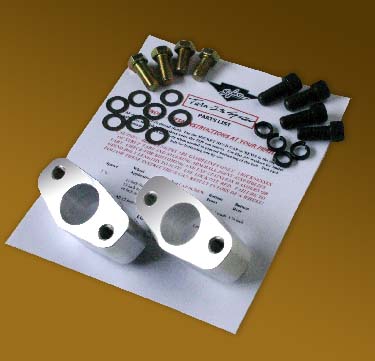
I just ordered a set of turn in spacers from Jim to see if they will work.
The question is, will they change the angle of the knuckles so much that they interfere with the brake rotor, we'll see.
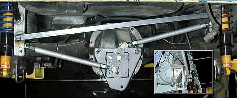
These cars have a 3 link suspension with a pan hard bar. The upper link is much shorter than the lower arms. Despite their size and weight, these cars are very good autocrossers/road racers.
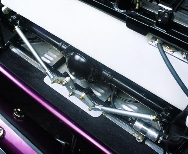
When I designed the 3 link for my STU RX7 I built it to use 3 equal length arms. Which is has. But after considering how the suspension will move in racing conditions I think I could have run a shorter upper arm and been fine. That is because with a stiff racing suspension on a relatively smooth race track the rear suspension have very little vertical travel. Almost all of the movement/angle change occurs out on the ends of the axle as the car moves through corner roll. Pictuers below of the 3 link I fab'd
The Lotus link suspension is a three link because the axle is located at three points. The lower lpoint is a ink ormed by a triangle that also serves to locate the axle laterally.
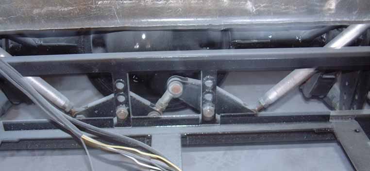
Chassis mount for the third link. Has 6 adjustment holes. The control arm is extruded aluminum with 5/8" Auora heims at both ends.

Third with cover in place. The mount is triangulated into the chassis on multiple planes for strength.


Hey Guys. Thanks to Kentetsu for pointing me here. I have not had as much time to hang out on the forums lately and thus had not seen this thread since the first few pages.
I hate to muck up such a good rear geometry thread with front end geometry stuff mostly relating to our rack kit. Shell we move the discussion to a new thread?
Someone mind posting a new thread and point me to it. I can then see if a mod will move the related post.
-billy
I hate to muck up such a good rear geometry thread with front end geometry stuff mostly relating to our rack kit. Shell we move the discussion to a new thread?
Someone mind posting a new thread and point me to it. I can then see if a mod will move the related post.
-billy
Joined: Feb 2006
Posts: 3,162
Likes: 1
From: London, Ontario, Canada
Mustanghammer: Very nice tri link setup! I'm planning to do something similar although I was going to mount it slightly lower and wasn't planning to make the cover around it so wide. Was there a reason you made the box around it so big? I wouldn't imagine the upper link would see that much side to side motion, just more of a twisting as one wheel goes up on a bump etc..
Mustanghammer: Very nice tri link setup! I'm planning to do something similar although I was going to mount it slightly lower and wasn't planning to make the cover around it so wide. Was there a reason you made the box around it so big? I wouldn't imagine the upper link would see that much side to side motion, just more of a twisting as one wheel goes up on a bump etc..
The mounting bracket is high to accomodate the location of the mount on the rear axle as well an adjustable ride height that will let the car get pretty low. Also to allow for a very wide range of adjustment at the chassis. I put this same suspension on a Mustang and was very suprised at some of the arm angles I had to use to make the car work in certain situations.